JP2005292014A - Controller unit of engine dynamometer - Google Patents
Controller unit of engine dynamometer Download PDFInfo
- Publication number
- JP2005292014A JP2005292014A JP2004109580A JP2004109580A JP2005292014A JP 2005292014 A JP2005292014 A JP 2005292014A JP 2004109580 A JP2004109580 A JP 2004109580A JP 2004109580 A JP2004109580 A JP 2004109580A JP 2005292014 A JP2005292014 A JP 2005292014A
- Authority
- JP
- Japan
- Prior art keywords
- control
- dynamometer
- engine
- value
- signal
- Prior art date
- Legal status (The legal status is an assumption and is not a legal conclusion. Google has not performed a legal analysis and makes no representation as to the accuracy of the status listed.)
- Pending
Links
- 230000004043 responsiveness Effects 0.000 claims abstract description 12
- 230000004044 response Effects 0.000 claims abstract description 6
- 238000001514 detection method Methods 0.000 claims description 17
- 238000000034 method Methods 0.000 description 7
- 238000010586 diagram Methods 0.000 description 5
- 230000000694 effects Effects 0.000 description 2
- 230000002265 prevention Effects 0.000 description 2
- 230000001052 transient effect Effects 0.000 description 2
- 238000012790 confirmation Methods 0.000 description 1
- 230000007613 environmental effect Effects 0.000 description 1
- 238000004904 shortening Methods 0.000 description 1
- 238000010998 test method Methods 0.000 description 1
Images
Landscapes
- Testing Of Engines (AREA)
Abstract
Description
本発明は、エンジンダイナモメータの制御装置に係わり、特にエンジン側とダイナモメータ側双方との制御精度バランスをよくして応答性を向上した制御装置に関するものである。 The present invention relates to a control device for an engine dynamometer, and more particularly to a control device that improves the control accuracy balance between the engine side and the dynamometer side to improve the response.
エンジンダイナモメータの制御装置で過渡モードの試験を行う場合、エンジン回転数とエンジントルクを制御し、規格に定められた運転が行われる。例えば、米国EPA(環境保護庁)による車両総重量8500ポンドを越える車両に搭載されたエンジンの排出ガス規制の試験法である1199モードによる過渡試験によれば、1秒毎のエンジン回転数、エンジントルク値が規定されており、この規定に従ってエンジンを運転する。運転時の目標となる回転数及びトルク値と運転結果(検出値)による回転数、トルク値から運転精度の判定が行われて試験の有効性の判断がなされる。 When the transient mode test is performed by the engine dynamometer control device, the engine speed and the engine torque are controlled, and the operation defined in the standard is performed. For example, according to a transient test in 1199 mode, which is a test method for exhaust gas regulations for engines mounted on vehicles with a total vehicle weight exceeding 8500 pounds by the US EPA (Environmental Protection Agency), engine revolutions per second, engine A torque value is specified, and the engine is operated according to this specification. The operational accuracy is determined from the rotational speed and torque value that are targets during operation and the rotational speed and torque value based on the operation result (detected value), and the validity of the test is determined.
通常、エンジンの回転とトルクを制御する場合、
a.エンジンを回転数制御とし、エンジンと連結されるダイナモメータをトルク制御する方法。
b.エンジンをトルク制御し、ダイナモメータを回転数制御とする方法。
の2方法がある。
Normally when controlling engine speed and torque,
a. A method of controlling the torque of an dynamometer connected to the engine by controlling the engine speed.
b. A method of controlling the torque of the engine and controlling the rotational speed of the dynamometer.
There are two methods.
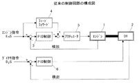
図3は従来の制御装置を示す概略構成図で、1は被試験機であるエンジン、2はこのエンジン1と連結されたダイナモメータである。3はPID制御部で、エンジン指令と検出されたエンジンの回転数信号との偏差信号が入力されてPID演算が行われる。4はフイードフォワード制御部で、エンジン指令に対応したエンジン出力推定値を出力し、この推定出力値とPID演算値との和信号がアクチュエータ制御部5に印加され、アクチュエータを介してエンジンの開度制御が実行される。6はダイナモメータ用のPID制御部で、ダイナモ指令と検出されたダイナモメータの回転数信号との偏差信号が入力されてPID演算が実行され、インバータ等の制御手段を介して速度制御が行われる。
FIG. 3 is a schematic configuration diagram showing a conventional control device, wherein 1 is an engine as a machine under test, and 2 is a dynamometer connected to the engine 1. A PID control unit 3 receives a deviation signal between the engine command and the detected engine speed signal, and performs PID calculation. A
なお、EPA1199モード対応のエンジンダイナモメータの制御装置としては、非特許文献1のようなものが知られている。
図3で示すエンジンダイナモメータの制御装置において、前述した制御方法aの場合、エンジン指令は開度設定信号であり、制御方法bの場合にはトルク設定信号となる。
一般に、ダイナモメータの制御応答はエンジンに比べて非常に速いため、ダイナモメータ側の制御は高精度で運転が可能となるが、エンジン制御は応答制御遅れ等により運転精度は悪くなっているため、エンジン制御のゲイン調整やフイードフォワード制御部4等を設けて制御精度の向上を図っている。
In the engine dynamometer control device shown in FIG. 3, in the case of the control method a described above, the engine command is an opening setting signal, and in the case of the control method b, it is a torque setting signal.
In general, the control response of the dynamometer is very fast compared to the engine, so the control on the dynamometer side can be operated with high accuracy, but the engine control is poor in operation accuracy due to response control delay, etc. Engine control gain adjustment,
一方、EPA1199モードでは、エンジン回転、トルク、及びエンジン出力についてぞぞれ精度設定の条件があり、前述した組み合わせでは、aの制御方法ではトルク精度がよく、bの制御方法では回転精度がよくなる傾向にある。したがって、試験時において運転精度が規定値を満たさない場合、学習運転や制御ゲイン調整を行い、全ての精度判定が満足となった状態で排ガス試験を行うことになる。このため、学習運転やゲイン調整は調整運転や判定確認試験の都度繰り返し実施されるため、本来の排ガス試験が完了するでに多くの時間を要している。 On the other hand, in the EPA 1199 mode, there are conditions for setting the accuracy of the engine rotation, torque, and engine output, respectively. With the combination described above, the torque accuracy tends to be good with the control method a, and the rotation accuracy tends to be good with the control method b. is there. Therefore, when the operation accuracy does not satisfy the specified value at the time of the test, the learning operation and the control gain adjustment are performed, and the exhaust gas test is performed in a state where all accuracy determinations are satisfied. For this reason, the learning operation and the gain adjustment are repeatedly performed every time the adjustment operation and the determination confirmation test are performed. Therefore, it takes a lot of time to complete the original exhaust gas test.
そこで、本発明が目的とするところは、制御装置の制御精度をバランスよく向上させ、調整時間の短縮できる制御装置を提供することにある。 Accordingly, an object of the present invention is to provide a control device capable of improving the control accuracy of the control device in a well-balanced manner and shortening the adjustment time.
本発明の第1は、エンジン制御系とダイナモメータ制御系とを備えた制御回路を用いて互いに連結されたエンジンとダイナモメータとを所定の運転モードに基づいて制御するエンジンダイナモメータの制御装置において、
判定調整部を設け、この判定調整部にて前記エンジン制御に対する目標値と検出の偏差値、及びダイナモメータ制御に対する目標値と検出の偏差値とを求め、エンジン制御に対する目標値と検出の偏差値に応じた信号をパラメータとしてダイナモメータ制御系の信号に加え、この信号に基づいてダイナモメータの応答性、ゲインを調整するよう構成したことを特徴としたものである。
A first aspect of the present invention is an engine dynamometer control device that controls an engine and a dynamometer connected to each other using a control circuit having an engine control system and a dynamometer control system based on a predetermined operation mode. ,
A determination adjustment unit is provided. The determination adjustment unit obtains a target value and detection deviation value for the engine control, and a target value and detection deviation value for the dynamometer control, and a target value and detection deviation value for the engine control. A signal according to the above is added as a parameter to the signal of the dynamometer control system, and the responsiveness and gain of the dynamometer are adjusted based on this signal.
本発明の第2は、前記判定調整部は、前記エンジン制御に対する目標値と検出の偏差値の大小を判定する判定手段と、この判定手段によって判定された偏差値に対応してダイナモメータ制御系の応答性を調整する調整手段を有したことを特徴としたものである。 According to a second aspect of the present invention, the determination adjustment unit is configured to determine a magnitude of a target value for the engine control and a detected deviation value, and a dynamometer control system corresponding to the deviation value determined by the determination unit. It has the adjustment means which adjusts the responsiveness of this.
本発明の第3は、第1の制御回路と第2の制御回路、及びこれら各制御回路を選択するための制御切換部を設け、前記第1,第2の制御回路のうち何れか一方に判定調整部を設け、この判定調整部にて前記エンジン制御に対する目標値と検出の偏差値、及びダイナモメータ制御に対する目標値と検出の偏差値とを求め、エンジン制御に対する目標値と検出の偏差値に応じた信号をパラメータとしてダイナモメータ制御系の信号に加え、この信号に基づいてダイナモメータの応答性、ゲインを調整するよう構成したことを特徴としたものである。 According to a third aspect of the present invention, a first control circuit, a second control circuit, and a control switching unit for selecting each of these control circuits are provided, and either one of the first and second control circuits is provided. A determination adjustment unit is provided. The determination adjustment unit obtains a target value and detection deviation value for the engine control, and a target value and detection deviation value for the dynamometer control, and a target value and detection deviation value for the engine control. A signal according to the above is added as a parameter to the signal of the dynamometer control system, and the responsiveness and gain of the dynamometer are adjusted based on this signal.
以上のとおり、本発明によれば、エンジン制御に対する目標値と検出の偏差値に応じた信号をパラメータとしてダイナモメータ制御系の信号に加え、この信号に基づいてダイナモメータの応答性、ゲインを調整するよう構成したものであるから、エンジン制御系とダイナモメータ制御系との制御バランスがよくなり、事前の調整運転に要する時間が短縮されて試験効率の向上が図れるものである。
また、従来においては、ダイナモメータ側にてトルク運転を行うとき、運転モードによってはエンジンの回転が追いつかない状態で過負荷をかけ、エンジンがストール状態となる場合もあったが、エンジン制御系とダイナモメータ制御系との制御バランスが取れたことにより、エンジンのストール現象も防止でる等の効果が生じるものである。
As described above, according to the present invention, a signal corresponding to the target value for engine control and the detected deviation value is added as a parameter to the signal of the dynamometer control system, and the responsiveness and gain of the dynamometer are adjusted based on this signal. Thus, the control balance between the engine control system and the dynamometer control system is improved, and the time required for prior adjustment operation is shortened, so that the test efficiency can be improved.
Also, in the past, when performing torque operation on the dynamometer side, depending on the operation mode, there was a case where overload was applied in a state where the engine rotation could not catch up, and the engine was in a stalled state. By having a control balance with the dynamometer control system, an effect such as prevention of an engine stall phenomenon occurs.
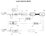
図1は、本発明の実施例を示す構成図である。同図において、10はエンジン、11はエンジンの回転速度を検出する回転検出器で、この検出器11での検出信号は加算部12に出力されてエンジン指令EnSと逆極性に加算される。13はPID制御部で、加算部12から入力された偏差信号に応じてPID演算を実行する。14はフイードフォワード制御部で、このフイードフォワード制御部はエンジン側が回転数制御の場合にはエンジン指令である開度設定値を取り込んでエンジン推定トルク出力値を加算部15に出力し、また、エンジン側がトルク制御の場合にはエンジン指令であるトルク設定値を取り込んでエンジン推定トルク出力値を加算部15に出力する。加算部15ではPID制御部13によるPID演算値とエンジン推定トルク値とを加算したた後、アクチュエータ制御部16に出力される。アクチュエータ制御部16では入力された信号に基づいて図示省略されたアクチュエータを介してエンジンスロットルを制御するよう構成される。そして、これら11〜16によってエンジン制御系を構成している。
FIG. 1 is a block diagram showing an embodiment of the present invention. In the figure, 10 is an engine, and 11 is a rotation detector for detecting the rotation speed of the engine. A detection signal from the
20はエンジン10と連結されたダイナモメータ、21はダイナモメータの回転速度を検出する検出器、22は加算部で、この加算部にはダイナモ指令DySと後述の判定調整部30の出力信号とが印加加算され、その加算信号はPID制御部23に入力されてPID演算される。24はインバータ等よりなる制御部で、この制御部を介してダイナモメータ20が制御される。そして、これら21〜24によってダイナモメータ制御系が構成される。
判定調整部30には判定手段と調整手段とを有し、エンジン制御系の指令値と検出値、及びダイナモメータ制御系の指令値と検出値とがそれぞれ入力されて各制御系の偏差値が求められ、エンジン制御系の偏差値を判定してその大小に応じたダイナモメータ制御系のPIDの比例ゲインや応答性を調整すべく判定調整部30は加算部22に調整信号を出力する。その際、判定手段は、エンジン指令値EnSと検出器11によって検出されたエンジンの回転速度信号とが入力されてエンジン制御に対する目標値と検出の偏差量を判定し、この偏差量に応じた信号をダイナモメータ制御系の制御信号にパラメータとして加える。調整手段は、求められたエンジン制御系の偏差量と検出器21によって検出されたダイナモメータの回転速度信号とダイナモ指令値DySとの偏差値とをもとにダイナモメータ制御系の応答性、ゲインの調整信号として加算部22に出力する。加算部22ではダイナモ指令値DySとの偏差が求められ、その偏差値に応じてPID制御部23でPID演算を実行し、この演算信号に基づいて制御部24を介してダイナモメータ20を制御する。
The
すなわち、エンジン制御系が運転モードに応じて制御が精度よく追従できず、目標値と検出値との間に誤差が生じたときに、その誤差量に応じてダイナモメータ制御系のPIDパラメータを調整することにより応答性とゲインが調整される。したがって、ダイナモメータ制御系の応答性は多少減じられるが、エンジン制御系とダイナモメータ制御系との制御バランスがよくなり、事前の調整運転に要する時間が短縮されて試験効率の向上が図れる。
また、従来においては、ダイナモメータ側にてトルク運転を行うとき、運転モードによってはエンジンの回転が追いつかない状態で過負荷をかけ、エンジンがストール状態となる場合もあったが、エンジン制御系とダイナモメータ制御系との制御バランスが取れたことにより、エンジンのストール現象も防止でる等の効果が生じる。
That is, when the engine control system cannot accurately follow the operation mode and an error occurs between the target value and the detected value, the PID parameter of the dynamometer control system is adjusted according to the error amount. By doing so, responsiveness and gain are adjusted. Accordingly, the responsiveness of the dynamometer control system is somewhat reduced, but the control balance between the engine control system and the dynamometer control system is improved, and the time required for the preparatory adjustment operation is shortened, thereby improving the test efficiency.
Also, in the past, when performing torque operation on the dynamometer side, depending on the operation mode, there was a case where overload was applied in a state where the engine rotation could not catch up, and the engine was in a stalled state. Due to the control balance with the dynamometer control system, an effect such as prevention of an engine stall phenomenon occurs.
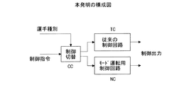
図2は他の実施例を示したものである。
エンジンダイナモメータの試験装置においては、試験する運転モードによっては必ずしもダイナモメータ制御系の応答性を抑制することはなく、幅広い試験設備を設置するためには、図3で示すような従来の装置も必要とする。図2はこのような試験設備に好適なもので、同図において、NCは第1の制御回路で、図1で示す制御回路が用いられて、例えばEPA1199モード時のようなモード運転用として用いる。TCは第2の制御回路で、この制御回路TCはエンジン制御系とダイナモメータ制御系とが干渉せずにそれぞれ独立した制御系を有した例えば図3のような従来より既知の回路が使用される。CCは制御切換部である。
制御切換部CCは入力された制御指令と運転種別信号から運転モードを判定し、第1若しくは第2の制御回路を選択して当該制御回路に切換える。
FIG. 2 shows another embodiment.
The engine dynamometer test device does not necessarily suppress the responsiveness of the dynamometer control system depending on the operation mode to be tested. In order to install a wide range of test equipment, the conventional device as shown in FIG. I need. FIG. 2 is suitable for such a test facility. In FIG. 2, NC is a first control circuit, and the control circuit shown in FIG. 1 is used, for example, for mode operation in the EPA 1199 mode. . TC is a second control circuit, and this control circuit TC uses a conventionally known circuit as shown in FIG. 3, for example, having an independent control system without interference between the engine control system and the dynamometer control system. The CC is a control switching unit.
The control switching unit CC determines the operation mode from the input control command and the operation type signal, selects the first or second control circuit, and switches to the control circuit.
10…エンジン
11,21…検出器
12,15,22…加算部
13,23…PID演算部
14…フィードフォワード制御部
16…アクチュエータ制御部
20…ダイナモメータ
23…PID演算部
24…制御部
30…判定調整部
10 ... Engine
11, 21 ... Detector
12, 15, 22 ... adder
13, 23 ... PID calculation section
14 ... Feedforward control unit
16 ... Actuator controller
20 ... Dynamometer
23 ... PID calculation section
24. Control unit
30. Determination adjustment unit
Claims (3)
判定調整部を設け、この判定調整部にて前記エンジン制御に対する目標値と検出の偏差値、及びダイナモメータ制御に対する目標値と検出の偏差値とを求め、エンジン制御に対する目標値と検出の偏差値に応じた信号をパラメータとしてダイナモメータ制御系の信号に加え、この信号に基づいてダイナモメータの応答性、ゲインを調整するよう構成したことを特徴としたエンジンダイナモメータの制御装置。 In an engine dynamometer control device that controls an engine and a dynamometer connected to each other using a control circuit having an engine control system and a dynamometer control system based on a predetermined operation mode,
A determination adjustment unit is provided. The determination adjustment unit obtains a target value and detection deviation value for the engine control, and a target value and detection deviation value for the dynamometer control, and a target value and detection deviation value for the engine control. A controller for an engine dynamometer characterized in that a signal corresponding to the above is added as a parameter to a signal of a dynamometer control system, and the response and gain of the dynamometer are adjusted based on this signal.
A first control circuit, a second control circuit, and a control switching unit for selecting each of these control circuits are provided, and a determination adjustment unit is provided in one of the first and second control circuits. The determination adjustment unit obtains a target value and detection deviation value for the engine control, and a target value and detection deviation value for the dynamometer control, and a signal corresponding to the target value and detection deviation value for the engine control is used as a parameter. 3. The engine dynamometer control device according to claim 1, wherein the dynamometer response and gain are adjusted based on the signal in addition to the signal of the dynamometer control system.
Priority Applications (1)
| Application Number | Priority Date | Filing Date | Title |
|---|---|---|---|
| JP2004109580A JP2005292014A (en) | 2004-04-02 | 2004-04-02 | Controller unit of engine dynamometer |
Applications Claiming Priority (1)
| Application Number | Priority Date | Filing Date | Title |
|---|---|---|---|
| JP2004109580A JP2005292014A (en) | 2004-04-02 | 2004-04-02 | Controller unit of engine dynamometer |
Publications (1)
| Publication Number | Publication Date |
|---|---|
| JP2005292014A true JP2005292014A (en) | 2005-10-20 |
Family
ID=35325094
Family Applications (1)
| Application Number | Title | Priority Date | Filing Date |
|---|---|---|---|
| JP2004109580A Pending JP2005292014A (en) | 2004-04-02 | 2004-04-02 | Controller unit of engine dynamometer |
Country Status (1)
| Country | Link |
|---|---|
| JP (1) | JP2005292014A (en) |
Cited By (2)
| Publication number | Priority date | Publication date | Assignee | Title |
|---|---|---|---|---|
| JP2008203053A (en) * | 2007-02-20 | 2008-09-04 | Meidensha Corp | Electric inertia control device in power measuring system |
| CN102778359A (en) * | 2011-05-09 | 2012-11-14 | Avl里斯脱有限公司 | Test rig for dynamic test assignments on internal combustion engines, and method for operating a test rig of this kind |
-
2004
- 2004-04-02 JP JP2004109580A patent/JP2005292014A/en active Pending
Cited By (4)
| Publication number | Priority date | Publication date | Assignee | Title |
|---|---|---|---|---|
| JP2008203053A (en) * | 2007-02-20 | 2008-09-04 | Meidensha Corp | Electric inertia control device in power measuring system |
| CN102778359A (en) * | 2011-05-09 | 2012-11-14 | Avl里斯脱有限公司 | Test rig for dynamic test assignments on internal combustion engines, and method for operating a test rig of this kind |
| JP2012237747A (en) * | 2011-05-09 | 2012-12-06 | Avl List Gmbh | Test device for dynamic test for combustion engine and method for operating the same |
| US8770019B2 (en) | 2011-05-09 | 2014-07-08 | Avl List Gmbh | Test rig for dynamic test assignments on internal combustion engines, and method for operating a test rig of this kind |
Similar Documents
| Publication | Publication Date | Title |
|---|---|---|
| US10464594B2 (en) | Model based driver torque estimation | |
| JP2008286614A (en) | Electric inertial control method | |
| KR20100126457A (en) | Vehicle speed control device | |
| JP2009276304A (en) | Vehicle behavior testing apparatus | |
| CN108351274B (en) | Engine test device and method | |
| JP6235420B2 (en) | Vehicle speed command generation device and vehicle speed command generation method | |
| US7638965B2 (en) | Motor control apparatus | |
| JP4645231B2 (en) | Power transmission system test apparatus and control method thereof | |
| JP2005292014A (en) | Controller unit of engine dynamometer | |
| JP2011160574A (en) | Speed control device for motor | |
| KR20190013873A (en) | Elevator control device | |
| JP6783740B2 (en) | Engine test equipment | |
| JP2009287987A (en) | Electric inertia control system of dynamometer | |
| JP2004177259A (en) | Controller for engine tester | |
| JP4019710B2 (en) | Engine bench system | |
| JP2013015352A (en) | Engine bench system control unit | |
| JP2003294584A (en) | Engine test equipment | |
| JP4019709B2 (en) | Engine bench system | |
| JP4591177B2 (en) | Engine test equipment | |
| JP2006197726A (en) | Positioning control device and positioning control method | |
| JPH0875613A (en) | Control system in engine dynamo bench | |
| JP2003344224A (en) | Power transmission system test apparatus and control method thereof | |
| JP2009044832A (en) | Method and device for controlling servo | |
| EP2020330A3 (en) | Method and Device for providing a target output value of a drive unit | |
| JP2003121307A (en) | Method for measuring inertial moment of engine |