JP2005292011A - Electromagnetic log sensor - Google Patents
Electromagnetic log sensor Download PDFInfo
- Publication number
- JP2005292011A JP2005292011A JP2004109544A JP2004109544A JP2005292011A JP 2005292011 A JP2005292011 A JP 2005292011A JP 2004109544 A JP2004109544 A JP 2004109544A JP 2004109544 A JP2004109544 A JP 2004109544A JP 2005292011 A JP2005292011 A JP 2005292011A
- Authority
- JP
- Japan
- Prior art keywords
- pair
- electromagnetic log
- log sensor
- flow paths
- ship
- Prior art date
- Legal status (The legal status is an assumption and is not a legal conclusion. Google has not performed a legal analysis and makes no representation as to the accuracy of the status listed.)
- Pending
Links
Images

Landscapes
- Navigation (AREA)
Abstract
【課題】 電磁ログセンサにおいて、船舶の進行方向に抵抗する水を取り入れる流路を形成し、その流路に非接触式の検出電極を配置すると共に、その流路の周囲を同電位で囲むようにして、外部からの電位差によるノイズが発生しない電磁ログセンサを提供する。
【解決手段】 電磁ログセンサは、船舶の進行方向に抵抗する水を取り入れることができる一対の流路と、前記一対の流路に対して磁界を生成する励磁コイルと、前記一対の流路のそれぞれに絶縁状態で配置した検出電極と、前記一対の流路のそれぞれに流路を取り囲むように配置すると共に前記検出電極の周囲に所定間隔だけ離した状態で配置したガード電極と、を備えてなる。
【選択図】 図1
PROBLEM TO BE SOLVED: To form a flow path for taking in water that resists the traveling direction of a ship in an electromagnetic log sensor, arrange a non-contact type detection electrode in the flow path, and surround the flow path with the same potential, An electromagnetic log sensor in which noise due to a potential difference from the outside does not occur is provided.
An electromagnetic log sensor includes a pair of flow paths that can take in water that resists the traveling direction of a ship, an excitation coil that generates a magnetic field for the pair of flow paths, and each of the pair of flow paths. A detection electrode disposed in an insulated state, and a guard electrode disposed so as to surround the flow channel in each of the pair of flow channels and spaced apart from the detection electrode by a predetermined interval. .
[Selection] Figure 1
Description
本発明は、電磁ログセンサに関し、詳しくは船舶の航行速度を測定する電磁ログセンサに関するものである。 The present invention relates to an electromagnetic log sensor, and more particularly to an electromagnetic log sensor that measures a navigation speed of a ship.
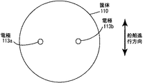
従来技術における電磁ログセンサは、船舶の航行速度計として利用され、図8及び図9に示すように、筒形状に形成した筐体110を船底に貫通させ、その先端部を水中に突出させて使用する。この電磁ログセンサの先端部には、コア111に巻かれたコイル112と、船舶の進行方向に対して左右に一対の電極113a、113bとが配設された構成になっている。
このコイル112に励磁電流ioを流すと、水中に磁界Φが存在する時に、船舶が図9に示す矢印で示す進行方向に沿って移動する。すると、電極113a、113bからは起電力eoが検出される。これは水(海水)を導体と考えた場合、磁界中を移動する導体中に起電力が発生する、所謂、ファラデーの電磁誘導の法則を応用したものである。
こうして、磁界Φの強度が一定である場合には電極113a、113bからは、船底と水との相対速度に比例した大きさの速度信号(起電力)が検出される。
The electromagnetic log sensor in the prior art is used as a navigation speedometer for a ship, and as shown in FIGS. 8 and 9, a
When the exciting current io is passed through the coil 112, the ship moves along the traveling direction indicated by the arrow shown in FIG. 9 when the magnetic field Φ exists in the water. Then, an electromotive force eo is detected from the electrodes 113a and 113b. When water (seawater) is considered as a conductor, this applies Faraday's law of electromagnetic induction, in which an electromotive force is generated in a conductor moving in a magnetic field.
Thus, when the intensity of the magnetic field Φ is constant, a speed signal (electromotive force) having a magnitude proportional to the relative speed between the ship bottom and water is detected from the electrodes 113a and 113b.
しかし、従来技術で説明した電磁ログセンサでは、先端部に電極があり、この電極が水(海水)と直接接するため、電極を含む先端部外皮表面に付着物等による汚損が生じ、出力の変動が生じるという問題がある。
又、このような出力の変動が生じるのを防ぐために、電極を含む先端部の付着物を除くメンテナンス作業を定期的に行わなければならないという問題もある。
更に、電極が水(海水)と直接接するため、この電極が汚損されていなくとも、流体浮遊物との接触により、ノイズが発生するという問題がある。
However, in the electromagnetic log sensor described in the prior art, there is an electrode at the tip, and this electrode is in direct contact with water (seawater). There is a problem that arises.
In addition, in order to prevent such fluctuations in output, there is a problem that maintenance work for removing deposits on the tip including the electrode must be performed periodically.
Furthermore, since the electrode is in direct contact with water (seawater), there is a problem that noise is generated due to contact with the fluid floating substance even if the electrode is not fouled.
従って、電極の汚損による出力の変動が生じることなく、定期的なメンテナンス作業を必要とすることなく、流体浮遊物との接触によるノイズの発生のない電磁ログセンサに解決しなければならない課題を有する。 Therefore, there is a problem that an electromagnetic log sensor that does not generate noise due to contact with a fluid floating substance without causing fluctuations in output due to electrode fouling, without requiring regular maintenance work, has to be solved.
上記課題を解決するために、本願発明の電磁ログセンサは、次に示す構成にしたことである。
(1)電磁ログセンサは、船舶の進行方向に抵抗する水を取り入れることができる一対の流路と、前記一対の流路に対して磁界を生成する励磁コイルと、前記一対の流路のそれぞれに絶縁状態で配置した検出電極と、前記一対の流路のそれぞれに流路を取り囲むように配置すると共に前記検出電極の周囲に所定間隔だけ離した状態で配置したガード電極と、を備えてなる。
(2)前記ガード電極には、前記検出電極で検出された信号を増幅し、該増幅した信号をフィードバックして印加するようにしたことを特徴とする(1)に記載の電磁ログセンサ。
(3)前記励磁コイルは、前記一対の流路を挟んだ位置に設けたことを特徴とする(1)に記載の電磁ログセンサ。
(4)前記一対の流路は、半円筒形状に形成して、その直線部分を背中合わせに形成したことを特徴とする(1)に記載の電磁ログセンサ。
In order to solve the above problems, the electromagnetic log sensor of the present invention is configured as follows.
(1) The electromagnetic log sensor includes a pair of flow paths that can take in water that resists the traveling direction of the ship, an excitation coil that generates a magnetic field for the pair of flow paths, and each of the pair of flow paths. A detection electrode disposed in an insulated state, and a guard electrode disposed so as to surround the flow path in each of the pair of flow paths and spaced apart from the detection electrode by a predetermined interval.
(2) The electromagnetic log sensor according to (1), wherein a signal detected by the detection electrode is amplified and the amplified signal is fed back and applied to the guard electrode.
(3) The electromagnetic log sensor according to (1), wherein the exciting coil is provided at a position between the pair of flow paths.
(4) The electromagnetic log sensor according to (1), wherein the pair of flow paths are formed in a semi-cylindrical shape, and the straight portions thereof are formed back to back.
(5)電磁ログセンサは、船舶の進行方向に対して水が通過する両側の側壁内側に絶縁状態で配置した一対の検出電極と、前記一対の検出電極を挟んだ位置に磁界を生成する励磁コイルと、前記一対の検出電極のそれぞれを覆うように所定の間隔を持って配置したガード電極と、を備えてなる。
(6)前記ガード電極には、前記検出電極で検出された信号を増幅し、該増幅した信号をフィードバックして印加するようにしたことを特徴とする(5)に記載の電磁ログセンサ。
(5) The electromagnetic log sensor includes a pair of detection electrodes arranged in an insulated state on the inner side walls on both sides through which water passes with respect to the traveling direction of the ship, and an excitation coil that generates a magnetic field at a position sandwiching the pair of detection electrodes And a guard electrode disposed at a predetermined interval so as to cover each of the pair of detection electrodes.
(6) The electromagnetic log sensor according to (5), wherein a signal detected by the detection electrode is amplified and the amplified signal is fed back and applied to the guard electrode.
本発明の電磁ログセンサは、検出電極を非接触式であるため、絶縁物付着による影響をほとんど受けなく、また、測定対象流体の周囲を同電位で囲むため、外部からの電位差によるノイズが発生しないという効果がある。 The electromagnetic log sensor of the present invention is not affected by adhesion of an insulator because the detection electrode is a non-contact type, and surrounds the fluid to be measured at the same potential, so that noise due to a potential difference from the outside does not occur. There is an effect.
以下、本発明の第1の実施例の電磁ログセンサについて、図面を用いて詳細に説明する。 The electromagnetic log sensor according to the first embodiment of the present invention will be described below in detail with reference to the drawings.
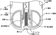
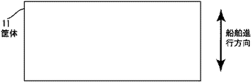
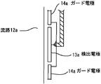
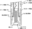
本発明の第1の実施例の電磁ログセンサは、図1〜図4に示すように、筐体11の両側に船舶の進行方向(図2参照)に抵抗する水を取り込むために半円筒形状に形成して、その直線部分を背中合わせにした流路12a、12bを一対形成し、この一対の流路12a、12bを挟む中央位置に鉄心15にコイル16を巻回した励磁コイル17を配置し、それぞれの流路12a、12bに対して絶縁させた位置に検出電極13a、13bを備えた構成になっている。そして、この検出電極13a、13bの外側には、これらの検出電極13a、13bの全体を覆い且つ流路12a、12bを覆うように検出電極13a、13bとは絶縁を保持したガード電極14a、14bが配置されている。一対の流路12a、12bのそれぞれには基準電位を検出するためのアース電極18a、18bが設けられている。このアース電極18a、18bは接液タイプ或は非接液タイプのどちらでもよく、実施例の場合は非接液タイプの構造となっている。
As shown in FIGS. 1 to 4, the electromagnetic log sensor according to the first embodiment of the present invention has a semi-cylindrical shape for taking in water that resists the traveling direction of the ship (see FIG. 2) on both sides of the casing 11. Forming a pair of flow paths 12a, 12b whose straight portions are back-to-back, and arranging an excitation coil 17 in which a coil 16 is wound around an iron core 15 at a central position sandwiching the pair of flow paths 12a, 12b, The detection electrodes 13a and 13b are provided at positions insulated from the respective flow paths 12a and 12b. Further, outside the detection electrodes 13a and 13b,
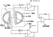
検出電極13a、13bは、図4に示すように、それぞれ高入力インピーダンスを持つプリアンプ19a、19bの非反転入力端(+)に接続され、その反転入力端(−)はそれぞれガード電極14a、14bに接続されると共にこれらのプリアンプ19a、19bの出力端に接続されている。そして、プリアンプ19a、19bの出力端は差動増幅器20の入力端にそれぞれ接続されている。
このように、ガード電極14a、14bには、検出電極13a、13bで検出された信号をプリアンプ19a、19bで増幅し、この増幅した信号をフィードバックして印加する構成になっている。
As shown in FIG. 4, the detection electrodes 13a and 13b are connected to the non-inverting input terminals (+) of the preamplifiers 19a and 19b having high input impedance, respectively, and the inverting input terminals (−) are respectively connected to the
As described above, the
このような構成の電磁ログセンサにおいて、励磁コイル17が励磁されると検出電極13a、13b近傍に磁界ができるため、船が図2に示す船舶進行方向に航走して一対の流路12a、12bに水(海水)が流れることにより励起される起電力は、1対の流路12a、12bのそれぞれに設けた検出電極13a、13bにより検出される。検出電極13a、13bは非接液タイプの容量式電極が採用され、一対の流路12a、12bのそれぞれの検出電極13a、13b及び同電位のガード電極14a、14bで囲んで測定対象流体を同電位で取り囲むことにより外来ノイズを防ぐことができるのである。
In the electromagnetic log sensor having such a configuration, when the excitation coil 17 is excited, a magnetic field is generated in the vicinity of the detection electrodes 13a and 13b, so that the ship sails in the ship traveling direction shown in FIG. 2 and the pair of flow paths 12a and 12b. The electromotive force excited by the flow of water (seawater) is detected by the detection electrodes 13a and 13b provided in the pair of flow paths 12a and 12b, respectively. Non-wetted capacitive electrodes are used as the detection electrodes 13a and 13b. The detection target fluid is surrounded by the detection electrodes 13a and 13b of the pair of flow paths 12a and 12b and the
次に、本願発明の第2の実施例の電磁ログセンサについて、図面を参照して説明する。 Next, an electromagnetic log sensor according to a second embodiment of the present invention will be described with reference to the drawings.
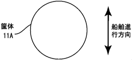
第2の実施例の電磁ログセンサは、図5〜図7に示すように、筒状の筐体11Aに形成され、その筐体11Aに対して船舶の進行方向(図6参照)に対して水が通過する両側の側壁内側に絶縁状態で配置した一対の検出電極13c、13dと、この一対の検出電極13c、13dを挟んだ位置に磁界を生成する鉄心15とコイル16からなる励磁コイル17と、一対の検出電極13c、13dのそれぞれの全体を覆うように所定の間隔を持って配置したガード電極14c、14dと、を備えた構成になっている。
As shown in FIGS. 5 to 7, the electromagnetic log sensor of the second embodiment is formed in a cylindrical casing 11 </ b> A, and is water with respect to the casing 11 </ b> A in the traveling direction of the ship (see FIG. 6). A pair of
そして、水(海水)が流れる側壁面のそれぞれには基準電位を検出するためのアース電極18c、18dが設けられている。このアース電極18c、18dは接液タイプ或は非接液タイプのどちらでもよく、実施例の場合は非接液タイプの構造となっている。 And each of the side wall surface through which water (seawater) flows is provided with ground electrodes 18c and 18d for detecting a reference potential. The earth electrodes 18c and 18d may be either a wetted type or a non-wetted type. In the embodiment, the ground electrodes 18c and 18d have a non-wetted type structure.
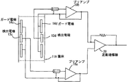
検出電極13c、13dは、図7に示すように、それぞれ高入力インピーダンスを持つプリアンプ19a、19bの非反転入力端(+)に接続され、その反転入力端(−)はそれぞれガード電極14c、14dに接続されると共にこれらのプリアンプ19a、19bの出力端に接続されている。そして、プリアンプ19a、19bの出力端は差動増幅器20の入力端にそれぞれ接続されている。
このように、ガード電極14c、14dには、検出電極13c、13dで検出された信号をプリアンプ19a、19bで増幅し、この増幅した信号をフィードバックして印加する構成になっている。
As shown in FIG. 7, the
As described above, the guard electrodes 14c and 14d are configured to amplify the signals detected by the
このような構成の電磁ログセンサにおいて、励磁コイル17が励磁されると検出電極13c、13d近傍に磁界ができるため、船が図6に示す船舶進行方向に航走して筐体11Aの両側面に水(海水)が流れることにより励起される起電力は、両壁面に設けた検出電極13c、13dにより検出される。検出電極13c、13dは非接液タイプの容量式電極が採用され、一対の検出電極13c、13d及び同電位のガード電極14c、14dで囲んで測定対象流体を同電位の状態で検出するため、外来ノイズを防ぐことができるのである。
In the electromagnetic log sensor having such a configuration, when the exciting coil 17 is excited, a magnetic field is generated in the vicinity of the
電磁ログセンサにおいて、船舶の進行方向に抵抗する水を取り入れる流路を形成し、その流路に非接触式の検出電極を配置すると共に、その流路の周囲を同電位で囲むため、外部からの電位差によるノイズが発生しない電磁ログセンサを提供する。 In the electromagnetic log sensor, a flow path for taking in water that resists the traveling direction of the ship is formed, a non-contact type detection electrode is arranged in the flow path, and the periphery of the flow path is surrounded by the same potential. An electromagnetic log sensor that does not generate noise due to a potential difference is provided.
11 筐体
11A 筐体
12a 流路
12b 流路
13a 検出電極
13b 検出電極
13c 検出電極
13d 検出電極
14a ガード電極
14b ガード電極
14c ガード電極
14d ガード電極
15 鉄心
16 コイル
17 励磁コイル
18a アース電極
18b アース電極
18c アース電極
18d アース電極
19a プリアンプ
19b プリアンプ
20 差動増幅器。
11
Claims (6)
前記一対の流路に対して磁界を生成する励磁コイルと、
前記一対の流路のそれぞれに絶縁状態で配置した検出電極と、
前記一対の流路のそれぞれに流路を取り囲むように配置すると共に前記検出電極の周囲に所定間隔だけ離した状態で配置したガード電極と、
を備えてなる電磁ログセンサ。 A pair of channels that can take in water that resists the direction of travel of the ship;
An exciting coil that generates a magnetic field for the pair of flow paths;
A detection electrode disposed in an insulated state in each of the pair of flow paths;
A guard electrode disposed in a state of surrounding the flow path in each of the pair of flow paths and separated by a predetermined interval around the detection electrode;
An electromagnetic log sensor comprising:
前記一対の検出電極を挟んだ位置に磁界を生成する励磁コイルと、
前記一対の検出電極のそれぞれを覆うように所定の間隔を持って配置したガード電極と、
を備えてなる電磁ログセンサ。 A pair of detection electrodes arranged in an insulated state on the inner side walls on both sides where water passes with respect to the traveling direction of the ship;
An exciting coil that generates a magnetic field at a position between the pair of detection electrodes;
A guard electrode disposed at a predetermined interval so as to cover each of the pair of detection electrodes;
An electromagnetic log sensor comprising:
6. The electromagnetic log sensor according to claim 5, wherein a signal detected by the detection electrode is amplified to the guard electrode, and the amplified signal is fed back and applied.
Priority Applications (1)
| Application Number | Priority Date | Filing Date | Title |
|---|---|---|---|
| JP2004109544A JP2005292011A (en) | 2004-04-02 | 2004-04-02 | Electromagnetic log sensor |
Applications Claiming Priority (1)
| Application Number | Priority Date | Filing Date | Title |
|---|---|---|---|
| JP2004109544A JP2005292011A (en) | 2004-04-02 | 2004-04-02 | Electromagnetic log sensor |
Publications (1)
| Publication Number | Publication Date |
|---|---|
| JP2005292011A true JP2005292011A (en) | 2005-10-20 |
Family
ID=35325091
Family Applications (1)
| Application Number | Title | Priority Date | Filing Date |
|---|---|---|---|
| JP2004109544A Pending JP2005292011A (en) | 2004-04-02 | 2004-04-02 | Electromagnetic log sensor |
Country Status (1)
| Country | Link |
|---|---|
| JP (1) | JP2005292011A (en) |
Cited By (4)
| Publication number | Priority date | Publication date | Assignee | Title |
|---|---|---|---|---|
| JP2010151450A (en) * | 2008-12-24 | 2010-07-08 | Yokogawa Denshikiki Co Ltd | Anti-fouling cover and water flow detection device |
| RU2407020C1 (en) * | 2009-09-04 | 2010-12-20 | Открытое акционерное общество "Концерн "Центральный научно-исследовательский институт "Электроприбор" | Receiving device of electromagnetic log |
| RU2503014C2 (en) * | 2011-12-23 | 2013-12-27 | Армен Ованесович Кочаров | Electromagnet log-drift sight |
| CN109406822A (en) * | 2018-11-29 | 2019-03-01 | 中国船舶重工集团公司第七0七研究所九江分部 | A kind of rod-type Planar integration sensor to test the speed for ship to water |
-
2004
- 2004-04-02 JP JP2004109544A patent/JP2005292011A/en active Pending
Cited By (5)
| Publication number | Priority date | Publication date | Assignee | Title |
|---|---|---|---|---|
| JP2010151450A (en) * | 2008-12-24 | 2010-07-08 | Yokogawa Denshikiki Co Ltd | Anti-fouling cover and water flow detection device |
| RU2407020C1 (en) * | 2009-09-04 | 2010-12-20 | Открытое акционерное общество "Концерн "Центральный научно-исследовательский институт "Электроприбор" | Receiving device of electromagnetic log |
| RU2503014C2 (en) * | 2011-12-23 | 2013-12-27 | Армен Ованесович Кочаров | Electromagnet log-drift sight |
| CN109406822A (en) * | 2018-11-29 | 2019-03-01 | 中国船舶重工集团公司第七0七研究所九江分部 | A kind of rod-type Planar integration sensor to test the speed for ship to water |
| CN109406822B (en) * | 2018-11-29 | 2024-02-09 | 中国船舶重工集团公司第七0七研究所九江分部 | Rod type plane integrated sensor for measuring speed of water of ship |
Similar Documents
| Publication | Publication Date | Title |
|---|---|---|
| KR900000660B1 (en) | Noncontact torque sensor | |
| JP5531217B2 (en) | Current sensor | |
| EP3430387B1 (en) | Guided wave testing | |
| KR102167578B1 (en) | Capacitive electromagnetic flowmeter | |
| JP6851785B2 (en) | Electromagnetic flow meter | |
| EP3726236A3 (en) | Current sensor having a flux concentrator for redirecting a magnetic field through two magnetic field sensing elements | |
| JP2012026966A (en) | Current sensor | |
| JP2008039734A (en) | Current sensor | |
| JP2005292011A (en) | Electromagnetic log sensor | |
| US20150042343A1 (en) | Object finder | |
| JP2012098202A (en) | Current sensor | |
| RU2338207C1 (en) | Velocity converter with electric jamming compensation | |
| US20240159603A1 (en) | Sensor head for load measuring device with magnetic coils | |
| KR102243759B1 (en) | Capacitive electromagnetic flowmeter | |
| JP3956388B2 (en) | Electromagnetic flow meter | |
| JP3204066B2 (en) | Capacitive electromagnetic flowmeter | |
| CA2558042A1 (en) | Electrode configuration for limca | |
| JPH04504470A (en) | induction flow meter | |
| SU1007015A1 (en) | Flow parameter electromagnetic converter | |
| JP2001281028A (en) | Electromagnetic flow meter | |
| SU723457A1 (en) | Device for measuring electroconductive liquid flow rate | |
| JPH09196956A (en) | Electromagnetic log sensor | |
| KR100359235B1 (en) | Electromagnetic flowmeter | |
| JPS6015178Y2 (en) | electromagnetic flow rate detector | |
| JPH08278175A (en) | Capacity type electromagnetic flow meter |