JP2005292006A - 科学装置および分離方法 - Google Patents
科学装置および分離方法 Download PDFInfo
- Publication number
- JP2005292006A JP2005292006A JP2004109350A JP2004109350A JP2005292006A JP 2005292006 A JP2005292006 A JP 2005292006A JP 2004109350 A JP2004109350 A JP 2004109350A JP 2004109350 A JP2004109350 A JP 2004109350A JP 2005292006 A JP2005292006 A JP 2005292006A
- Authority
- JP
- Japan
- Prior art keywords
- separation
- eluent
- sample
- flow
- plate
- Prior art date
- Legal status (The legal status is an assumption and is not a legal conclusion. Google has not performed a legal analysis and makes no representation as to the accuracy of the status listed.)
- Granted
Links
- 238000000926 separation method Methods 0.000 title claims abstract description 140
- 238000010008 shearing Methods 0.000 claims abstract description 11
- 239000013543 active substance Substances 0.000 claims description 12
- 239000003480 eluent Substances 0.000 abstract description 101
- 239000003463 adsorbent Substances 0.000 abstract description 90
- 238000000034 method Methods 0.000 abstract description 39
- 238000013375 chromatographic separation Methods 0.000 abstract description 26
- 239000000126 substance Substances 0.000 abstract description 13
- 238000006243 chemical reaction Methods 0.000 abstract description 12
- 239000007788 liquid Substances 0.000 abstract description 6
- 239000007809 chemical reaction catalyst Substances 0.000 abstract description 3
- 238000002474 experimental method Methods 0.000 description 71
- 238000009826 distribution Methods 0.000 description 60
- 241001012508 Carpiodes cyprinus Species 0.000 description 41
- 239000010408 film Substances 0.000 description 30
- 239000000975 dye Substances 0.000 description 27
- 239000012071 phase Substances 0.000 description 24
- BDERNNFJNOPAEC-UHFFFAOYSA-N propan-1-ol Chemical compound CCCO BDERNNFJNOPAEC-UHFFFAOYSA-N 0.000 description 18
- 239000001045 blue dye Substances 0.000 description 17
- 239000001044 red dye Substances 0.000 description 17
- 238000004587 chromatography analysis Methods 0.000 description 16
- 239000000243 solution Substances 0.000 description 15
- 238000009792 diffusion process Methods 0.000 description 14
- 238000010586 diagram Methods 0.000 description 13
- 238000005516 engineering process Methods 0.000 description 12
- 239000010409 thin film Substances 0.000 description 11
- 239000002245 particle Substances 0.000 description 9
- 230000005526 G1 to G0 transition Effects 0.000 description 8
- 238000013461 design Methods 0.000 description 8
- 239000011521 glass Substances 0.000 description 8
- 239000011259 mixed solution Substances 0.000 description 8
- 230000008569 process Effects 0.000 description 8
- VYPSYNLAJGMNEJ-UHFFFAOYSA-N Silicium dioxide Chemical compound O=[Si]=O VYPSYNLAJGMNEJ-UHFFFAOYSA-N 0.000 description 7
- 238000004364 calculation method Methods 0.000 description 7
- 239000000047 product Substances 0.000 description 7
- RBTBFTRPCNLSDE-UHFFFAOYSA-N 3,7-bis(dimethylamino)phenothiazin-5-ium Chemical compound C1=CC(N(C)C)=CC2=[S+]C3=CC(N(C)C)=CC=C3N=C21 RBTBFTRPCNLSDE-UHFFFAOYSA-N 0.000 description 6
- BDAGIHXWWSANSR-UHFFFAOYSA-N methanoic acid Natural products OC=O BDAGIHXWWSANSR-UHFFFAOYSA-N 0.000 description 6
- 229960000907 methylthioninium chloride Drugs 0.000 description 6
- 239000000203 mixture Substances 0.000 description 6
- PYWVYCXTNDRMGF-UHFFFAOYSA-N rhodamine B Chemical compound [Cl-].C=12C=CC(=[N+](CC)CC)C=C2OC2=CC(N(CC)CC)=CC=C2C=1C1=CC=CC=C1C(O)=O PYWVYCXTNDRMGF-UHFFFAOYSA-N 0.000 description 6
- 229940043267 rhodamine b Drugs 0.000 description 6
- 125000006850 spacer group Chemical group 0.000 description 6
- 239000004809 Teflon Substances 0.000 description 5
- 229920006362 Teflon® Polymers 0.000 description 5
- 239000003054 catalyst Substances 0.000 description 5
- 238000002156 mixing Methods 0.000 description 5
- 230000008859 change Effects 0.000 description 4
- 238000012856 packing Methods 0.000 description 4
- 239000002994 raw material Substances 0.000 description 4
- 239000002904 solvent Substances 0.000 description 4
- OSWFIVFLDKOXQC-UHFFFAOYSA-N 4-(3-methoxyphenyl)aniline Chemical compound COC1=CC=CC(C=2C=CC(N)=CC=2)=C1 OSWFIVFLDKOXQC-UHFFFAOYSA-N 0.000 description 3
- 239000002253 acid Substances 0.000 description 3
- 238000004458 analytical method Methods 0.000 description 3
- 239000003795 chemical substances by application Substances 0.000 description 3
- 238000009795 derivation Methods 0.000 description 3
- 239000000835 fiber Substances 0.000 description 3
- 235000019253 formic acid Nutrition 0.000 description 3
- 238000010191 image analysis Methods 0.000 description 3
- 238000003703 image analysis method Methods 0.000 description 3
- 238000002955 isolation Methods 0.000 description 3
- 239000000377 silicon dioxide Substances 0.000 description 3
- 238000001179 sorption measurement Methods 0.000 description 3
- 238000012546 transfer Methods 0.000 description 3
- XUIMIQQOPSSXEZ-UHFFFAOYSA-N Silicon Chemical compound [Si] XUIMIQQOPSSXEZ-UHFFFAOYSA-N 0.000 description 2
- 239000007795 chemical reaction product Substances 0.000 description 2
- 230000007423 decrease Effects 0.000 description 2
- 239000006185 dispersion Substances 0.000 description 2
- 238000001035 drying Methods 0.000 description 2
- 238000000605 extraction Methods 0.000 description 2
- 239000000945 filler Substances 0.000 description 2
- 239000012530 fluid Substances 0.000 description 2
- 238000003780 insertion Methods 0.000 description 2
- 230000037431 insertion Effects 0.000 description 2
- 230000010354 integration Effects 0.000 description 2
- 230000007246 mechanism Effects 0.000 description 2
- 238000005459 micromachining Methods 0.000 description 2
- 230000002093 peripheral effect Effects 0.000 description 2
- 229910052710 silicon Inorganic materials 0.000 description 2
- 239000010703 silicon Substances 0.000 description 2
- 102100030852 Run domain Beclin-1-interacting and cysteine-rich domain-containing protein Human genes 0.000 description 1
- 230000009471 action Effects 0.000 description 1
- 239000002390 adhesive tape Substances 0.000 description 1
- 238000010364 biochemical engineering Methods 0.000 description 1
- 230000015572 biosynthetic process Effects 0.000 description 1
- 230000000740 bleeding effect Effects 0.000 description 1
- 230000005465 channeling Effects 0.000 description 1
- 239000011248 coating agent Substances 0.000 description 1
- 238000000576 coating method Methods 0.000 description 1
- 238000004440 column chromatography Methods 0.000 description 1
- 239000002131 composite material Substances 0.000 description 1
- 230000003247 decreasing effect Effects 0.000 description 1
- 235000012489 doughnuts Nutrition 0.000 description 1
- 230000000694 effects Effects 0.000 description 1
- 238000010828 elution Methods 0.000 description 1
- 239000003822 epoxy resin Substances 0.000 description 1
- 238000011156 evaluation Methods 0.000 description 1
- 239000000284 extract Substances 0.000 description 1
- 238000004128 high performance liquid chromatography Methods 0.000 description 1
- 238000005286 illumination Methods 0.000 description 1
- 238000004811 liquid chromatography Methods 0.000 description 1
- 239000007791 liquid phase Substances 0.000 description 1
- 239000000463 material Substances 0.000 description 1
- 238000012986 modification Methods 0.000 description 1
- 230000004048 modification Effects 0.000 description 1
- 230000000704 physical effect Effects 0.000 description 1
- 229920000647 polyepoxide Polymers 0.000 description 1
- 238000012545 processing Methods 0.000 description 1
- 238000005086 pumping Methods 0.000 description 1
- 238000011160 research Methods 0.000 description 1
- 230000000717 retained effect Effects 0.000 description 1
- 230000011218 segmentation Effects 0.000 description 1
- 239000000741 silica gel Substances 0.000 description 1
- 229910002027 silica gel Inorganic materials 0.000 description 1
- 239000007787 solid Substances 0.000 description 1
- 241000894007 species Species 0.000 description 1
- 238000003786 synthesis reaction Methods 0.000 description 1
- 230000001131 transforming effect Effects 0.000 description 1
Images


Classifications
-
- G—PHYSICS
- G01—MEASURING; TESTING
- G01N—INVESTIGATING OR ANALYSING MATERIALS BY DETERMINING THEIR CHEMICAL OR PHYSICAL PROPERTIES
- G01N30/00—Investigating or analysing materials by separation into components using adsorption, absorption or similar phenomena or using ion-exchange, e.g. chromatography or field flow fractionation
- G01N30/0005—Field flow fractionation
Landscapes
- Physics & Mathematics (AREA)
- Health & Medical Sciences (AREA)
- Life Sciences & Earth Sciences (AREA)
- Chemical & Material Sciences (AREA)
- Analytical Chemistry (AREA)
- Biochemistry (AREA)
- General Health & Medical Sciences (AREA)
- General Physics & Mathematics (AREA)
- Immunology (AREA)
- Pathology (AREA)
- Physical Or Chemical Processes And Apparatus (AREA)
- Treatment Of Liquids With Adsorbents In General (AREA)
Abstract
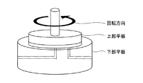
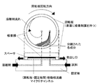
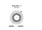
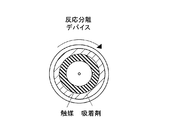
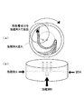
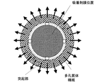
【解決手段】 本発明のマイクロ化学装置は、薄層吸着剤膜や反応触媒膜を持つ2枚の円形型平行平板を用いて、上板に吸着剤膜を貼り、その板を回転させることにより円周方向に溶離剤のせん断流れを発生させる。また同時に円形平板中心から外側に向けて溶離剤を流すことにより、中心から外周方向へと溶離剤のポアズイユ流れを作り、十字流を、2枚の円形型平行平板で挟まれるマイクロ空間で作る。その中に、分離したい液を流すことにより、連続分離あるいは連続反応分離を行うことができる。流量、回転速度などの操作条件と装置形状を変えることにより、分離効率、および分離した物質の取り出し口を変えることができる。
【選択図】 図2
Description
(1)単位体積あたりの表面積が非常に大きい
(2)レイノルズ数が小さいので層流が容易に達成できる
(3)微少量での合成が可能となる
等である。上記の特長に起因し、下記のような事柄が期待される。すなわち、
(1)温度制御が精密に、効率よく行える
(2)界面での反応が効率よく行える
(3)効率的な混合が行える
等である。
Gino V. Baron他、「On the possibility of shear−driven chromatography: a theoretical performance analysis」、Journal Chromatogr. A, (1999), 855, 57−70 「Continuous Annular Chromatography」、Advances in Biochemical Engineering Biotechnology 76 Modern Advances in Chromatography, Springer Gino V.Baron他、「The Possibility of Generating High−Seed Shear−Driven Flows and Their Potential Application in Liquid Chromatography」、Anal. Chem. (2000), 72, 2160−2165 Gino V. Baron,他、「Experimental demonstration of the possibility to perform shear−driven chromatographic separations in micro−channels」、Journal Chromatogr. A, (2001), 924, 111−122 Desmet G.、他、「Experimental Van Deemter plots of shear−driven liquid chromatographic separations in disposable microchannels」、Journal Chromatogr. A, (2003), 987, 39−48
(1)圧力を駆動力としない、せん断力駆動による連続式分離技術であること
(2)平行平板でつくるマイクロ空間で分離する技術であること
(3)回転によりせん断流れを発生させる技術であること
(4)吸着剤・触媒を平行平板に貼り、分子の親和性の差からくる拡散の違いによる差を利用した分離あるいは、反応させながら同時に分離を行える技術であること
(5)回転によりせん断流れを限られた時間だけかけることにより、連続式だけではなく回分式にも利用できる技術であること
(6)回分式に利用することにより、回転式せん断力駆動型クロマト分析装置としても使えること
である。
(1)ポンプの送液性や、装置の圧力の制限を受けずに分離が行える。
(2)従来のクロマト分離法では、吸着剤を流れのチャネリングが起こらないように充填する必要があったが、そのような難しさはなくなり、吸着剤を貼るだけの装置であり、操作性が格段を向上させることができる。
(3)回転円形板を連続的に回転させることにより、連続式にクロマト分離することが可能となった。また、円盤を所定の時間に限定して回転させることにより、分析用途にも使えるような技術とすることができる。
(4)円形板に吸着剤を薄膜塗布するだけでなく、触媒を円盤中心に外側に同心円状に吸着剤を塗布することにより、反応・分離プロセスを同時に行うことができる。
本発明は、SDC技術を拡張し、CACの連続化技術を取り入れた連続分離可能なせん断駆動型クロマト分離デバイス(科学装置)の開発を目的とする。
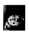
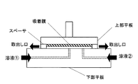
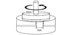
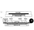
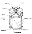
開発したクロマト分離デバイスの写真を図1に、全体の概略図を図2、図3、図4に示す。
〔3.1.1 新規デバイスマイクロ空間内での流動〕
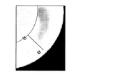
開発したデバイスにおける座標を図7に示す。マイクロチャンネル内ではθ方向(回転方向)にクエット(Couette)流れが、r方向(半径方向)にポアズイユ(Poiseuille)流れが生じている。クエット流れはせん断力駆動に由来し、直線形の速度プロファイルであり、ポアズイユ流れは圧力駆動に由来し、放物線形の速度プロファイルである。
開発したデバイスのクロマト分離性能評価を目的とし、回分分離実験、連続分離実験を行った。回分分離実験ではクエット、ポアズイユ各流れ場における分離実験を行ない、クロマトグラフィーの性能評価関数である理論段高さ(HETP;The Height of Equivalent to the Theoretical Plate)を算出した。理論段高さが小さいほどクロマト性能は良好である。また、クエット・ポアズイユ複合流れ場である連続分離実験も行った。
〔3.2.1 クエット流れ場〕
〔3.2.1.1 実験装置〕
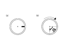
クエット流れ場における回分分離実験には上部、下部平板とも直径8cmの新規デバイスを用いた。吸着剤膜に試料入口位置(中心から2cmの位置)から半径方向に外周まで直線状に幅1mmの溝を作製し、実験開始時に試料を線状に配置できるようにしてある。
吸着剤薄膜には先に述べたようにTLCシリカプレート(Whatman K6 60Å)を用いた。
(1)溶離剤側シリンジポンプを稼動させ、マイクロチャンネル内に溶離剤を満たす。その後、溶離剤の供給を止める。
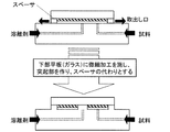
〔3.2.2.1 実験装置〕
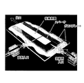
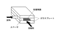
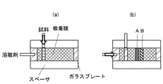
ポアズイユ流れ場における回分分離実験には平板型デバイスを用いた。平板型デバイスの構成を図9に、概略図を図10に示す。平板型デバイスは二枚のガラスプレートからなり、一方のガラスプレート表面に吸着剤を塗布した。つまりガラスプレートの一方(吸着剤を塗布してある方)はTLCプレートそのものである。吸着剤膜厚は新規デバイスと同様に80μmである。二枚のガラスプレート間にスペーサ(厚さ130μmのテフロン(登録商標)シート)を挟み、マイクロチャンネルを作製している。よってマイクロチャンネルの厚さは約50μmであり、チャンネル厚さ、吸着剤膜厚などのカラムサイズはすべて新規デバイスと同じである。二枚のガラスプレートの接合にはエポキシ樹脂を用いた。
試料はクエット流れ場における回分分離実験と同様である。
(1)溶離剤側シリンジポンプを稼動させ、マイクロチャンネル内に溶離剤を満たす。その後、溶離剤の供給を止める。
〔3.3.1 実験装置〕
連続分離実験には上部平板直径12cm、下部平板直径16cmのデバイスを用いた。
試料は回分分離実験と同様である。
(1)レオメータのモータを稼動させ、上部平板を回転させながら、溶離剤側シリンジポンプを稼動し、マイクロチャンネル内に溶離剤を満たす。上部平板回転速度は0.01rpmに設定した。この際、比較的流量を多くし、チャンネル内の微小気泡を取り除く必要がある。
〔3.4.1 画像解析法〕
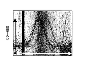
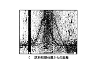
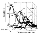
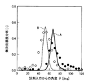
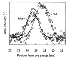
回分分離実験および連続分離実験後、吸着剤膜表面をスキャナーで画像に収め、その画像を解析する。具体的には染料の各成分(青色、赤色)のカラー強度をプロットする。クエット流れ場における回分分離実験では半径30mmの円周上のカラー強度分布を、ポアズイユ流れ場における回分分離実験では溶離剤流れに水平に適当な直線上のカラー強度分布を、連続分離実験では半径25、30、35mmの円周上のカラー強度分布を求めた。

〔4.1 カラー強度プロット〕
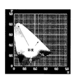
カラー強度プロットの例としてクエット流れ場における回分分離実験結果を示す。図15に分離実験後の吸着剤表面画像を示した。図15中の円周上のカラー強度をプロットし、図16に示した。図16より今回用いた画像解析法は各色のカラー強度を良く表現できていることがわかる。
クエット流れ場における回分分離実験より本実験で用いた系における各試料成分の容量係数を算出した。容量係数は式(4.2.a)より算出した。
回分分離実験結果より各操作条件において理論段高さを算出した。理論段高さを実験的に求める場合、式(4.3.a)を用いる。
開発したデバイスのカラム形式(一方の平板に吸着剤薄膜を配置した平板型カラム)におけるHETP理論式を求めた。先に述べたように本デバイスマイクロ空間内ではθ方向にクエット流れが、r方向にポアズイユ流れが生じている。よって、平板型カラムでの各流れ場におけるHETP理論式が必要となる。クエット流れ場における理論式は参考文献より式(4.4.a)で与えられる。
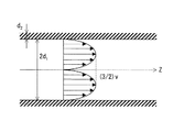
ポアズイユ流れ場におけるHETP理論式を参考文献の手順に従い導出した。必要なHETP理論式を得るため、想定したカラム形状と速度プロファイルを図19に示した。
〔4.5.1 クエット流れ場〕
〔4.5.1.1 容量係数〕
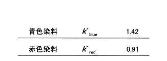
4.2で述べた方法により本実験で用いた系における青色、赤色それぞれの容量係数を算出した。
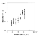
4.3で述べた方法により理論段高さを算出し図23に示す。横軸は溶離剤平均流速、縦軸は理論段高さであり、青色の丸は青色染料、赤色の丸は赤色染料の結果を示している。3.2.1.3で述べたように回転板(上部平板)は0.01、0,015、0.02、0.025、0.03、0.035、0.04rpmで操作し、各回転速度で二回ずつ分離実験を行なった。吸着剤表面において半径30mmの円周上のカラー強度を解析することにより理論段高さを算出している。よって溶離剤平均流速はその円周上での流速である。
〔4.5.2.1 容量係数と溶離剤平均流速〕
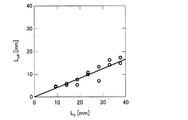
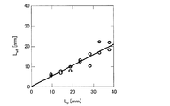
3.2.2.3で述べたようにポアズイユ流れ場における回分分離実験では平板型デバイスを用いており、シリンジポンプ設定値から溶離剤平均流速を算出することは困難である。画像解析を行うことによりカラー強度分布ピーク位置の移動距離Leffがわかり、容量係数は既知である(4.5.1.1参照)として式(4.2.a)より溶離剤の移動距離L0を算出できる。これと実験時間(分離前から分離後までの経過時間)より溶離剤平均流速を算出した。
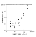
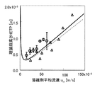
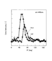
4.3で述べた方法により理論段高さを算出し図25に示す。横軸は溶離剤平均流速、縦軸は理論段高さであり、塗りつぶした三角は青色染料、塗りつぶしていない三角は赤色染料の結果を示している。溶離剤平均流速の算出方法は4.5.2.1で述べた。
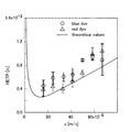
回分分離実験の結果(理論段高さ)を青色染料、赤色染料ごとにそれぞれ図26、図27に示す。横軸には溶離剤平均流速を、縦軸には理論段高さをとり、図中の丸はクエット流れ場での、三角はポアズイユ流れ場での回分分離実験の結果である。また実線、破線はそれぞれクエット流れ場、ポアズイユ流れ場における理論値であり、クエット流れ場については式(4.4.a)、ポアズイユ流れ場については式(4.4.b)より算出した(4.4参照)。ここでは移動相分子拡散係数をDm=1.0E−9 m2/s、固定相分子拡散係数をDs=1.0E−10 m2/sとした。文献を参考にし、適当な各拡散係数の値を選んだ。
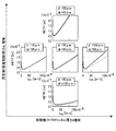
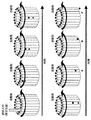
図28に移動相(マイクロチャンネル)厚さおよび固定相(吸着剤膜)厚さを変化させた場合の理論段高さの変化の様子を示した。各グラフの縦軸は理論段高さを、横軸は溶離剤平均流速を表し、理論段高さは理論式(式(4.4.a)、(4.4.b))を用いて算出した。実線はクエット流れ場における理論値、破線はポアズイユ流れ場における理論値を示している。容量係数k’は1.42とし、移動相分子拡散係数Dm、固定相分子拡散係数Dsはそれぞれ1E−9、1E−10 m2/sとし、グラフ中にマイクロチャンネル厚さdと吸着剤膜厚さdfの各条件を示した。
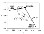
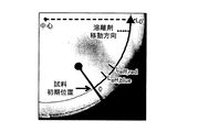
4.6.1で装置外周における取出し口位置の違いにより連続分離が可能であることがわかった。その一方で開発したデバイスの操作条件を決定するためには試料軌跡を推算しなければならない。試料軌跡を求めるとは濃度分布ピーク位置の軌道と濃度分布幅を算出することである。すなわち各ピーク位置における溶離剤移動方向の法線方向に幅を持たせるように濃度分布幅を足し合わせればよい。ここで溶離剤移動方向とはクエット流れを考えた場合はθ方向、ポアズイユ流れを考えた場合はr方向となる。クエット流れによるピークの広がり、つまり濃度分布幅とポアズイユ流れによる濃度分布幅をそれぞれ単独で算出して、それらを比較し、よりブロードな試料軌跡を表現しているものをクエット、ポアズイユ複合流れ場での濃度分布幅とした。
ここではポアズイユ流れによるピークの広がりのみを考え、ポアズイユ流れ場における濃度分布幅算出方法を述べる。新規デバイスマイクロ空間内では溶離剤流速は半径rの関数である。そこで、濃度分布幅を算出する際、式(4.6.2.c)において微小変化を考え、積分する必要がある。
クエット流れによるピークの広がりとポアズイユ流れによるピークの広がりをそれぞれ単独で考えた場合、クエット流れはθ方向に、ポアズイユ流れはr方向に濃度分布を生じさせ、その濃度分布はガウス関数に従うとみなせる。よって、4.6.2で示した方法によりクエット流れによるθ方向の濃度分布幅およびポアズイユ流れによるr方向の濃度分布幅を算出できる。ガウス関数はピーク幅を与えることで一義的に決定することができるので、クエット、ポアズイユ流れを単独で考えた場合、それぞれθ方向およびr方向の濃度分布を算出することができる。任意の円周上について、クエット流れによるピークの広がりのみを考慮して算出した濃度分布とポアズイユ流れによるピークの広がりのみを考慮して濃度分布を重ねあわせ、算術平均をとることにより、クエット、ポアズイユ複合流れ場におけるその円周上の濃度分布とみなした。
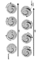
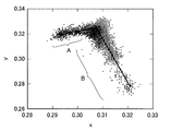
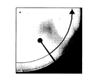
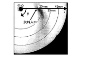
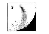
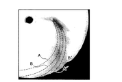
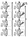
同条件で連続分離実験を行ない、実験後の吸着剤表面画像を図37および図38に示す。また図中には4.6.2で述べた推算した試料軌跡を合わせて示した。図中、点線A−点線A’の範囲が青色成分の軌跡を示し、点線B−点線B’の範囲が赤色成分の軌跡を示している。両図は連続分離の再現性を表している。
〔4.7.1 設計方程式〕
以上まとめとして開発したデバイスにおける簡易提案法を提案する。簡易設計法における設計方程式は式(4.4.a)、(4.4.b)、(4.6.2.b)、(4.6.2.c)である。
デバイス設計および操作条件の決定の手順を示す。
分離したい成分にたいして適当な容量係数k’を与えるような吸着剤、溶離剤を選定する。ここで移動相分子拡散係数Dm、固定相分子拡散係数Dsが定まる。
回分分離実験結果(4.5.3)で示したように、HETP理論式(式(4.4.a)(4.4.b))を用いてクロマト性能を予測することができる。したがって分離が十分達成される程度までチャンネル厚さd、吸着剤膜厚さdfを微小化し決定する。
連続分離実験結果(4.6.2)で示したように、濃度分布ピーク位置の軌道を式(4.6.2.a)、濃度分布幅を式(4.6.2.b)から求められ、試料軌跡を推算できるので所望の取出し口位置で各成分が得られるように溶離剤流量FE、回転速度ωを決定する。試料流量を大幅に変更することができないので、溶離剤流量を決定すれば全流量(試料と溶離剤の合計流量)FTは決定される。装置上部平板半径(吸着剤膜半径)routは任意であるが、ここでroutを変更と適当な溶離剤流量FE、回転速度ωは変化する。
開発したデバイスの特徴として以下の二点が挙げられる。
・粒子充填型ではなく、薄層状の吸着剤膜を使用。
・平板型デバイスで、マイクロ空間での特長を利用し、界面積を確保。
Claims (2)
- 複数の平行平板を有し、当該平行平板の、少なくとも一つの試料投入口を有する板Aと、作用物質を表面に有する板Bとについて、板Bの作用物質を有する面を当該板Aと向かい合わせに配置し、当該板A又はBの少なくとも一つの板を回転させることができる機能を有し、板A又は板Bの外周部に生成物の取出し口を有することを特徴とする科学装置。
- 試料を相向かい合う板に存在させ、当該板同士の一方又は双方を回転させることで生じるせん断応力により当該試料より生じる生成物を分離することを特徴とする分離方法。
Priority Applications (1)
| Application Number | Priority Date | Filing Date | Title |
|---|---|---|---|
| JP2004109350A JP4455917B2 (ja) | 2004-04-01 | 2004-04-01 | 科学装置および分離方法 |
Applications Claiming Priority (1)
| Application Number | Priority Date | Filing Date | Title |
|---|---|---|---|
| JP2004109350A JP4455917B2 (ja) | 2004-04-01 | 2004-04-01 | 科学装置および分離方法 |
Publications (2)
| Publication Number | Publication Date |
|---|---|
| JP2005292006A true JP2005292006A (ja) | 2005-10-20 |
| JP4455917B2 JP4455917B2 (ja) | 2010-04-21 |
Family
ID=35325088
Family Applications (1)
| Application Number | Title | Priority Date | Filing Date |
|---|---|---|---|
| JP2004109350A Expired - Fee Related JP4455917B2 (ja) | 2004-04-01 | 2004-04-01 | 科学装置および分離方法 |
Country Status (1)
| Country | Link |
|---|---|
| JP (1) | JP4455917B2 (ja) |
Cited By (6)
| Publication number | Priority date | Publication date | Assignee | Title |
|---|---|---|---|---|
| JP2014522295A (ja) * | 2011-05-02 | 2014-09-04 | テクニッシュ ウニバルシテイト アイントホーフェン | 多相接触及び単相接触のための装置 |
| US11452322B2 (en) | 2015-11-16 | 2022-09-27 | Q Sports Science, LLC | Traumatic brain injury protection devices |
| US11478253B2 (en) | 2013-03-15 | 2022-10-25 | Tbi Innovations Llc | Methods and devices to reduce the likelihood of injury from concussive or blast forces |
| US11696766B2 (en) | 2009-09-11 | 2023-07-11 | Tbi Innovations, Llc | Methods and devices to reduce damaging effects of concussive or blast forces on a subject |
| US11969033B2 (en) | 2016-03-02 | 2024-04-30 | Q30 Sports Science, Llc | Methods and devices to reduce damaging effects of concussive or blast forces on a subject |
| WO2025119394A1 (zh) * | 2023-12-07 | 2025-06-12 | 广西东和环保科技有限公司 | 微流液路结构,包含该液路的设备及其操作方法 |
-
2004
- 2004-04-01 JP JP2004109350A patent/JP4455917B2/ja not_active Expired - Fee Related
Cited By (9)
| Publication number | Priority date | Publication date | Assignee | Title |
|---|---|---|---|---|
| US11696766B2 (en) | 2009-09-11 | 2023-07-11 | Tbi Innovations, Llc | Methods and devices to reduce damaging effects of concussive or blast forces on a subject |
| US12285177B2 (en) | 2009-09-11 | 2025-04-29 | Tbi Innovations, Llc | Methods and devices to reduce damaging effects of concussive or blast forces on a subject |
| JP2014522295A (ja) * | 2011-05-02 | 2014-09-04 | テクニッシュ ウニバルシテイト アイントホーフェン | 多相接触及び単相接触のための装置 |
| US11478253B2 (en) | 2013-03-15 | 2022-10-25 | Tbi Innovations Llc | Methods and devices to reduce the likelihood of injury from concussive or blast forces |
| US12137917B2 (en) | 2013-03-15 | 2024-11-12 | Tbi Innovations, Llc | Methods and devices to reduce the likelihood of injury from concussive or blast forces |
| US11452322B2 (en) | 2015-11-16 | 2022-09-27 | Q Sports Science, LLC | Traumatic brain injury protection devices |
| US12329219B2 (en) | 2015-11-16 | 2025-06-17 | Q30 Sports Science, Llc | Traumatic brain injury protection devices |
| US11969033B2 (en) | 2016-03-02 | 2024-04-30 | Q30 Sports Science, Llc | Methods and devices to reduce damaging effects of concussive or blast forces on a subject |
| WO2025119394A1 (zh) * | 2023-12-07 | 2025-06-12 | 广西东和环保科技有限公司 | 微流液路结构,包含该液路的设备及其操作方法 |
Also Published As
| Publication number | Publication date |
|---|---|
| JP4455917B2 (ja) | 2010-04-21 |
Similar Documents
| Publication | Publication Date | Title |
|---|---|---|
| Lazar et al. | Multiple open-channel electroosmotic pumping system for microfluidic sample handling | |
| Lam et al. | Recent advances in open tubular capillary liquid chromatography | |
| US6919046B2 (en) | Microfluidic analytical devices and methods | |
| EP1338894B1 (en) | Mobile phase gradient generation microfluidic device | |
| Stone et al. | Engineering flows in small devices: microfluidics toward a lab-on-a-chip | |
| Ericson et al. | Electroosmosis-and pressure-driven chromatography in chips using continuous beds | |
| Sharp et al. | Liquid flows in microchannels | |
| He et al. | Concentrating solutes and nanoparticles within individual aqueous microdroplets | |
| Pumera | Microchip-based electrochromatography: designs and applications | |
| Faure | Liquid chromatography on chip | |
| Greenwood et al. | Sample manipulation in micro total analytical systems | |
| JPH08105873A (ja) | 流動物質の分離のための装置と方法 | |
| Thurmann et al. | A low pressure on-chip injection strategy for high-performance chip-based chromatography | |
| Wang et al. | Ultra-thin liquid film extraction based on a gas–liquid–liquid double emulsion in a microchannel device | |
| JP4455917B2 (ja) | 科学装置および分離方法 | |
| Lu et al. | Contactless manipulation of mixed phase fluids in liquid crystal polymer microtubes assisted with light-driven vortex | |
| Yamada et al. | Tube radial distribution chromatography system developed by combining commercially available HPLC system and open-tubular capillary tube as separation column | |
| Eichhorn | Microfluidic sorting of stereoisomers | |
| Penrose et al. | Development and assessment of a miniaturised centrifugal chromatograph for reversed-phase separations in micro-channels | |
| Li et al. | Dead-end filling of SlipChip evaluated theoretically and experimentally as a function of the surface chemistry and the gap size between the plates for lubricated and dry SlipChips | |
| Schlund et al. | Continuous sampling and analysis by on-chip liquid/solid chromatography | |
| Medina et al. | Open tubular liquid chromatography: Recent advances and future trends | |
| Neumann et al. | Fluidic Platforms and Components of Lab-on-a-Chip devices | |
| Ríos et al. | Chip-based separation devices coupled to mass spectrometry in food and environmental chemistry | |
| Sikanen | Microchip technology in metabolomics |
Legal Events
| Date | Code | Title | Description |
|---|---|---|---|
| A621 | Written request for application examination |
Free format text: JAPANESE INTERMEDIATE CODE: A621 Effective date: 20070329 |
|
| A711 | Notification of change in applicant |
Free format text: JAPANESE INTERMEDIATE CODE: A712 Effective date: 20070329 |
|
| A521 | Written amendment |
Free format text: JAPANESE INTERMEDIATE CODE: A821 Effective date: 20070329 |
|
| A711 | Notification of change in applicant |
Free format text: JAPANESE INTERMEDIATE CODE: A711 Effective date: 20070517 |
|
| A521 | Written amendment |
Free format text: JAPANESE INTERMEDIATE CODE: A821 Effective date: 20070517 |
|
| A977 | Report on retrieval |
Free format text: JAPANESE INTERMEDIATE CODE: A971007 Effective date: 20090701 |
|
| A131 | Notification of reasons for refusal |
Free format text: JAPANESE INTERMEDIATE CODE: A131 Effective date: 20090929 |
|
| A521 | Written amendment |
Free format text: JAPANESE INTERMEDIATE CODE: A523 Effective date: 20091126 |
|
| TRDD | Decision of grant or rejection written | ||
| A01 | Written decision to grant a patent or to grant a registration (utility model) |
Free format text: JAPANESE INTERMEDIATE CODE: A01 Effective date: 20100112 |
|
| A01 | Written decision to grant a patent or to grant a registration (utility model) |
Free format text: JAPANESE INTERMEDIATE CODE: A01 |
|
| A61 | First payment of annual fees (during grant procedure) |
Free format text: JAPANESE INTERMEDIATE CODE: A61 Effective date: 20100204 |
|
| FPAY | Renewal fee payment (event date is renewal date of database) |
Free format text: PAYMENT UNTIL: 20130212 Year of fee payment: 3 |
|
| R150 | Certificate of patent or registration of utility model |
Free format text: JAPANESE INTERMEDIATE CODE: R150 |
|
| FPAY | Renewal fee payment (event date is renewal date of database) |
Free format text: PAYMENT UNTIL: 20140212 Year of fee payment: 4 |
|
| R250 | Receipt of annual fees |
Free format text: JAPANESE INTERMEDIATE CODE: R250 |
|
| R250 | Receipt of annual fees |
Free format text: JAPANESE INTERMEDIATE CODE: R250 |
|
| R250 | Receipt of annual fees |
Free format text: JAPANESE INTERMEDIATE CODE: R250 |
|
| LAPS | Cancellation because of no payment of annual fees |