JP2005291976A - Indicating instrument system - Google Patents
Indicating instrument system Download PDFInfo
- Publication number
- JP2005291976A JP2005291976A JP2004108631A JP2004108631A JP2005291976A JP 2005291976 A JP2005291976 A JP 2005291976A JP 2004108631 A JP2004108631 A JP 2004108631A JP 2004108631 A JP2004108631 A JP 2004108631A JP 2005291976 A JP2005291976 A JP 2005291976A
- Authority
- JP
- Japan
- Prior art keywords
- engine speed
- value
- indicating instrument
- correction data
- indicator
- Prior art date
- Legal status (The legal status is an assumption and is not a legal conclusion. Google has not performed a legal analysis and makes no representation as to the accuracy of the status listed.)
- Pending
Links
- 238000012937 correction Methods 0.000 claims abstract description 129
- 238000005259 measurement Methods 0.000 claims abstract description 43
- 230000000737 periodic effect Effects 0.000 abstract 1
- 238000013500 data storage Methods 0.000 description 31
- 239000000919 ceramic Substances 0.000 description 17
- 230000010355 oscillation Effects 0.000 description 11
- 238000000034 method Methods 0.000 description 7
- 238000004891 communication Methods 0.000 description 6
- 230000006870 function Effects 0.000 description 6
- 238000003384 imaging method Methods 0.000 description 6
- 238000010586 diagram Methods 0.000 description 5
- 238000006243 chemical reaction Methods 0.000 description 4
- 230000003247 decreasing effect Effects 0.000 description 3
- 230000007274 generation of a signal involved in cell-cell signaling Effects 0.000 description 3
- 238000007493 shaping process Methods 0.000 description 3
- 238000013459 approach Methods 0.000 description 2
- 230000004397 blinking Effects 0.000 description 2
- 238000004364 calculation method Methods 0.000 description 2
- 239000013078 crystal Substances 0.000 description 2
- 238000010191 image analysis Methods 0.000 description 2
- 238000012545 processing Methods 0.000 description 2
- 230000000007 visual effect Effects 0.000 description 2
- 238000004519 manufacturing process Methods 0.000 description 1
Images


Landscapes
- Indicating Measured Values (AREA)
- Instrument Panels (AREA)
Abstract
Description
本発明は、エンジン回転数等を表示する車両用の指示計器装置に係り、詳しくは、予め設定したエンジン回転数等に達したことを表示する機能(レブインジケータ機能)を備えたものに好適な指示計器装置に関する。 The present invention relates to an indicating instrument device for a vehicle that displays an engine speed or the like, and more specifically, suitable for a device having a function (rev indicator function) for displaying that a preset engine speed or the like has been reached. The present invention relates to an indicating instrument device.
エンジン回転数が所定値に達したことを報知するようにした計器装置や表示装置は、従来から知られている(例えば、特許文献1および2参照)。
An instrument device and a display device for notifying that the engine speed has reached a predetermined value are conventionally known (for example, see
交差コイル式計器を用いたタコメータ(エンジン回転数計)は、エンジン回転数に応じた信号(例えば、イグニッションコイルの1次側パルス信号やクランク軸回転センサの出力信号等)の周波数(周期)を測定してエンジン回転数に変換し、エンジン回転数に応じた角度の信号を出力し指針表示する。レブインジケータは、エンジン回転数が予め設定した回転数に達した際に、インジケータ(表示部)を発光させたりブザー等を鳴動させたりすることで報知するものである。報知回転数の設定は、回転数設定キー等の操作に基づいてタコメータの指針を例えば250rpmステップで所定時間間隔で動かし、指針が所望の回転数を指示した時点で再度回転数設定キー等を操作することでなされる。なお、報知回転数の設定は、エンジンが停止している状態でのみ行なうことができるようにしている。 A tachometer (engine speed meter) using a cross coil type meter calculates the frequency (cycle) of a signal (for example, a primary side pulse signal of an ignition coil or an output signal of a crankshaft rotation sensor) according to the engine speed. Measure and convert to engine speed, output angle signal according to engine speed, and display pointer. When the engine speed reaches a preset rotational speed, the rev indicator notifies the indicator (display unit) by emitting light or sounding a buzzer or the like. The notification speed is set by moving the tachometer pointer at a predetermined time interval, for example, at 250 rpm steps based on the operation of the speed setting key, etc., and operating the speed setting key again when the pointer indicates the desired speed. Is done. The notification rotation speed can be set only when the engine is stopped.
交差コイル式計器を用いた指示計器装置では、その製造時に所定の信号を入力させ、指針が所定の値を指示するように調整するための指示調整データ(補正データ)を求め、その指示調整データ(補正データ)を書き込み可能な不揮発性メモリ(EEPROM等)に書き込むことで、より正確な指示がなされるようにしている。(例えば、特許文献3参照)。 In the indicating instrument device using the cross coil type instrument, a predetermined signal is input at the time of manufacture, instruction adjustment data (correction data) for adjusting the pointer to indicate a predetermined value is obtained, and the instruction adjustment data is obtained. By writing (correction data) in a writable non-volatile memory (such as an EEPROM), a more accurate instruction can be given. (For example, refer to Patent Document 3).
また、周波数精度が低いクロック信号をシステムクロック(マイコン駆動用クロック)とした場合でも、周波数(または周期)のカウント値(計測値)や出力時間の設定等を周波数誤差(公称周波数と実際の周波数とのずれ量)に基づいて補正することで、誤差の発生を抑制するようにした制御装置(電子制御装置)は、知られている(例えば、特許文献4および5参照)。
周波数精度の高い振動子(例えば水晶振動子)を使用して高精度のシステムクロックを発生し、そのシステムクロックまたはそれを分周して得たクロックに基づいて、エンジン回転数に応じた信号(例えば、イグニッションコイルの1次側パルス信号やクランク軸回転センサの出力信号等)の周波数(周期)を測定した場合には、エンジン回転数をほぼ正確に求めることができる。したがって、タコメータ用の指示調整データ(補正データ)とレブインジケータでの回転数設定時の指示調整データ(補正データ)とは同一(共通)のものを使用できる。 A high-accuracy system clock (for example, a crystal oscillator) is used to generate a high-accuracy system clock. Based on the system clock or a clock obtained by dividing the system clock, a signal corresponding to the engine speed ( For example, when the frequency (cycle) of the ignition side pulse signal of the ignition coil, the output signal of the crankshaft rotation sensor, etc.) is measured, the engine speed can be obtained almost accurately. Therefore, the same (common) data can be used for the tachometer instruction adjustment data (correction data) and the instruction adjustment data (correction data) at the time of setting the rotation speed with the rev indicator.
しかしながら、周波数精度の低い振動子(例えばセラミック振動子)を使用してシステムクロックを発生させるようにした場合、周波数(周期)の測定結果(エンジン回転数の測定結果)にはシステムクロックの公称周波数と実際の周波数とのずれに応じた誤差が生ずる。そこで、測定結果(エンジン回転数の測定結果)の誤差を含めて指針の指示値を補正する指示調整データ(補正データ)を求め、その指示調整データ(補正データ)をEEPROM等に書き込むようにすると、レブインジケータでの回転数設定時の指示値にずれが生じてしまう。 However, when a system clock is generated using a vibrator with low frequency accuracy (for example, a ceramic vibrator), the frequency (period) measurement result (engine speed measurement result) is the nominal frequency of the system clock. An error corresponding to the difference between the actual frequency and the actual frequency occurs. Therefore, when the instruction adjustment data (correction data) for correcting the instruction value of the pointer including the error of the measurement result (measurement result of the engine speed) is obtained, the instruction adjustment data (correction data) is written in the EEPROM or the like. The indication value at the time of setting the number of revolutions with the rev indicator will be shifted.
本発明はこのような課題を解決するためなされたもので、周波数精度の低い発振子を使用した場合でも指示精度を確保できる指示計器装置を提供することを目的とする。 The present invention has been made to solve such a problem, and an object of the present invention is to provide an indicating instrument device that can ensure an indicating accuracy even when an oscillator having a low frequency accuracy is used.
前記課題を解決するため本発明に係る指示計器装置は、エンジン回転数に応じた入力信号の周期または周波数を測定することでエンジン回転数を求め、指針がエンジン回転数に応じた指示値を指示するように指示計器を駆動する指示計器装置であって、エンジン回転数に応じた指示値のずれを補正するためのタコメータ用補正データを記憶する手段と、レブインジケータの回転数を設定するために指示計器を駆動する際に回転数に応じた指示値のずれを補正するためのレブインジケータ設定用補正データを記憶する手段と、エンジン回転数を表示する場合にはタコメータ用補正データに基づいて指示値の補正を行なうとともにレブインジケータの回転数を設定するために指示計器を駆動する場合にはレブインジケータ設定用補正データに基づいて指示値の補正を行なう指示値補正手段とを備えることを特徴とする。 In order to solve the above-mentioned problem, the indicating instrument device according to the present invention obtains the engine speed by measuring the cycle or frequency of the input signal according to the engine speed, and the pointer indicates the indicated value according to the engine speed. An indicating instrument device for driving an indicating instrument so as to store a tachometer correction data for correcting a deviation of an instruction value according to an engine speed, and to set a rotation speed of a rev indicator Means for storing rev indicator setting correction data for correcting the deviation of the indicated value according to the rotational speed when driving the indicating instrument, and when displaying the engine rotational speed, the instruction is based on the tachometer correction data. When the indicator is driven to correct the value and set the rotation speed of the rev indicator, it is based on the rev indicator setting correction data. Characterized in that it comprises an instruction value correcting means for correcting the instruction value each.
また、本発明に係る他の指示計器装置は、エンジン回転数に応じた入力信号の周期または周波数を測定することでエンジン回転数を求め、求めたエンジン回転数を表示する指示計器装置であって、基準とするクロック周波数と実際のクロック周波数とのずれによって生ずるエンジン回転数の測定値のずれを補正する測定値補正手段を備えることを特徴とする。 Another indicating instrument device according to the present invention is an indicating instrument device that obtains an engine speed by measuring a cycle or frequency of an input signal corresponding to the engine speed and displays the obtained engine speed. And a measurement value correcting means for correcting a difference in the measured value of the engine speed caused by a difference between the reference clock frequency and the actual clock frequency.
なお、本発明に係る他の指示計器装置は、エンジン回転数を測定して表示するものだけでなく、車速に応じた入力信号を測定して車速を表示するもの等にも適用できる。 The other indicating instrument device according to the present invention can be applied not only to measuring and displaying the engine speed but also to displaying the vehicle speed by measuring the input signal according to the vehicle speed.
本発明に係る指示計器装置は、エンジン回転数を表示する際にはタコメータ用補正データに基づいて指示値を補正するので、エンジン回転数を精度良く指示させることができる。また、レブインジケータの回転数を設定する際にはレブインジケータ設定用補正データに基づいて指示値を補正するので、設定対象となる回転数を精度良く指示させることができる。したがって、タコメータの指示値とレブインジケータの回転数設定時の指示値とにずれが生ずることがない。 Since the indicating instrument device according to the present invention corrects the indicated value based on the tachometer correction data when displaying the engine speed, the engine speed can be indicated with high accuracy. Further, when setting the rotation speed of the rev indicator, the instruction value is corrected based on the correction data for setting the rev indicator, so that the rotation speed to be set can be instructed with high accuracy. Therefore, there is no difference between the indicated value of the tachometer and the indicated value when the rotation number of the rev indicator is set.
また、本発明に係る他の指示計器装置は、基準とするクロック周波数と実際のクロック周波数とのずれによって生ずる測定値のずれを補正する測定値補正手段を備えているので、周波数精度の低い振動子を用いる場合でもエンジン回転数や車速を正確に測定して表示することができる。 In addition, the other indicating instrument device according to the present invention includes the measurement value correcting means for correcting the deviation of the measurement value caused by the deviation between the reference clock frequency and the actual clock frequency. Even when a child is used, the engine speed and the vehicle speed can be accurately measured and displayed.
以下、発明を実施するための最良の形態を実施例に基づいて説明する。 Hereinafter, the best mode for carrying out the invention will be described based on examples.
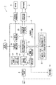
図1は本発明の第1実施例に係る指示計器装置の構成を示す図である。図1に示す指示計器装置1は、レブ(REV)インジケータ機能を備えたエンジン回転数計(タコメータ)である。レブインジケータ機能とは、エンジン回転数が予め設定した回転数に達した際にそれを報知する機能である。
FIG. 1 is a diagram showing a configuration of an indicating instrument device according to a first embodiment of the present invention. The
この指示計器装置1は、CPU、ROM、RAM、入出力インタフェース回路等を備えたマイクロコンピュータシステムからなる制御部(マイコン部)2と、EEPROM等の書き込み可能な不揮発性メモリからなる補正データ記憶手段(EEPROM)3と、エンジン回転数を表示する指示計器4と、指示計器駆動回路5と、エンジン回転数が予め設定した回転数に達したことを可視表示や可聴表示によって報知する表示部6と、表示部駆動回路7と、エンジン回転数に応じた入力信号を波形整形してエンジン回転数に応じたパルス信号を出力する波形整形回路8と、回転数を設定するための設定操作部9とからなる。
The indicating
指示計器4としては、交差コイル式のものやステッピングモータ式のものを用いることができる。エンジン回転数に応じた入力信号としては、イグニッションコイルの1次側パルス信号やクランク軸回転センサからのパルス信号を用いることができる。補正データ記憶手段(EEPROM)3には、エンジン回転数の指針指示値を補正するためのタコメータ用補正データ31、および、レブインジケータの報知回転数を設定する際の指針指示値を補正するためのレブンジケータ設定用補正データ32がそれぞれ格納されている。表示部6は、発光ダイオードやランプ等の可視表示器とブザー等の可聴表示器とを備える。
As the indicating instrument 4, a cross coil type or a stepping motor type can be used. As an input signal corresponding to the engine speed, a primary pulse signal of an ignition coil or a pulse signal from a crankshaft rotation sensor can be used. The correction data storage means (EEPROM) 3 is used for correcting the
制御部(マイコン部)2は、セラミック振動子21と、クロック発生回路22と、エンジン回転数測定手段23と、指示角度設定手段(指示値補正手段)24と、指示計器駆動信号生成手段25と、回転数設定手段26と、表示制御手段27と、調整制御手段28と、シリアル通信手段29等を備える。
The control unit (microcomputer unit) 2 includes a
クロック発生回路22は、セラミック振動子21によって定まる周波数のシステムクロック(マイコン駆動用クロック)を生成するとともに、システムクロックを所定の分周数で分周した基準クロックを生成する。
The
エンジン回転数測定手段23は、波形整形された入力信号の周期または周波数を基準クロックに基づいて計測し、計測した周期または周波数に基づいてエンジン回転数を演算し、所定回数のエンジン回転数測定値の平均値を求めて出力する。このエンジン回転数測定手段23は、予め設定した基準クロックの基準周期に基づいて入力信号の周期または周波数を計測する。ここで、基準周期とはセラミック振動子21の公称周波数に対応して設定される周期である。したがって、セラミック振動子21の周波数(実際の発振周波数)が公称周波数と一致している場合には、入力信号の周期または周波数が正確に測定され、正確なエンジン回転数が求まる。セラミック振動子21の周波数(実際の発振周波数)が公称周波数に対してずれている場合は、そのずれ量に応じた計測誤差が生ずる。例えば、セラミック振動子21の周波数(実際の発振周波数)が公称値に対して例えば5%低い場合には、測定されたエンジン回転数は実際の回転数よりも5%低くなる。
The engine speed measuring means 23 measures the period or frequency of the waveform-shaped input signal based on the reference clock, calculates the engine speed based on the measured period or frequency, and measures the engine speed measured value a predetermined number of times. Find the average value of and output. The engine speed measuring means 23 measures the cycle or frequency of the input signal based on a preset reference cycle of the reference clock. Here, the reference period is a period set corresponding to the nominal frequency of the
指示角度設定手段(指示値補正手段)24は、エンジン回転数測定手段23によって測定されたエンジン回転数を入力として指示角度を求めて出力する。指示角度設定手段(指示値補正手段)24は、エンジン回転数と指示角度との関係が予め登録された指示角度テーブル(図示しない)および補正データ記憶手段(EEPROM)3に格納されているタコメータ用補正データ31を参照して指示角度を演算する。指示角度テーブルは、図示しないROMに格納されている。指示角度テーブルは、補正データ記憶手段(EEPROM)3に格納するようにしてもよい。指示角度テーブルには、複数のエンジン回転数に対して指示角度がそれぞれ設定されている。指示角度テーブルには、エンジン回転数−指示角度の代表的な特性が格納されている。
The indicated angle setting means (indicated value correcting means) 24 obtains and outputs the indicated angle with the engine speed measured by the engine speed measuring means 23 as an input. The indicated angle setting means (indicated value correcting means) 24 is for a tachometer stored in an indicated angle table (not shown) and correction data storage means (EEPROM) 3 in which the relationship between the engine speed and the indicated angle is registered in advance. The indicated angle is calculated with reference to the
補正データ記憶手段(EEPROM)3には、指示計器装置1の製造時等に図1において仮想線で示す調整装置10等を用いて指針の指示値を調整した際の補正データが格納されている。指示角度テーブルおよび補正データ記憶手段(EEPROM)3には、それぞれ複数のポイント(エンジン回転数)に対して補正データが設定されている。指示角度設定手段(指示値補正手段)24は、複数のポイント間を直線補間することで、エンジン回転数に対する指示角度を演算によって求める。求められた指示角度は、指示計器駆動信号生成手段25および表示制御手段27に供給される。 The correction data storage means (EEPROM) 3 stores correction data when the indicated value of the pointer is adjusted using the adjusting device 10 indicated by a virtual line in FIG. . In the command angle table and the correction data storage means (EEPROM) 3, correction data is set for each of a plurality of points (engine speed). The command angle setting means (command value correction means) 24 obtains the command angle with respect to the engine speed by calculation by linear interpolation between a plurality of points. The obtained indication angle is supplied to the indicating instrument drive signal generating means 25 and the display control means 27.
指示計器4に交差コイル式のものを用いる場合、指示計器駆動信号生成手段25は、指示角度設定手段(指示値補正手段)24によって設定された指示角度に基づいてサイン波特性のPWM信号およびコサイン波特性のPWM信号をそれぞれ生成して出力する。各PWM信号は、指示計器駆動回路5によって電力増幅され、指示計器(交差コイル式計器)の各コイルに供給される。これにより、交差コイル式計器内の回転磁石が回動され、回転磁石に連結された指針によってエンジン回転数が指示される。指示計器駆動信号生成手段25は、図示しないROMに予め格納されている指示角度−デューティ比変換テーブルを参照してデューティ比および駆動極性を求め、求めたデューティ比および駆動極性のPWM信号を生成する。
When the crossed coil type is used for the indicating instrument 4, the indicating instrument drive signal generating means 25 generates a sine wave characteristic PWM signal based on the indicated angle set by the indicated angle setting means (indicated value correcting means) 24. Generate and output cosine wave characteristic PWM signals. Each PWM signal is power-amplified by the indicating
指示計器4にステッピングモータ式のものを用いる場合、指示計器駆動信号生成手段25は、指示角度設定手段(指示値補正手段)24によって設定された指示角度に基づいてステッピングモータ式指示計器を駆動する信号(指示角度に対応した電気角の信号)を生成して出力する。ステッピングモータ式指示計器を駆動する信号は、指示計器駆動回路5によって電力増幅され、ステッピングモータ式計器の各コイルに供給される。これにより、ステッピングモータ式指示計器の指針が駆動され、エンジン回転数が指示される。指示計器駆動信号生成手段25は、図示しないROMに予め格納されている指示角度−電気角変換テーブルを参照してステッピングモータ式指示計器の各相コイルへ供給する信号を生成する。
When a stepping motor type is used for the indicating instrument 4, the indicating instrument drive signal generating means 25 drives the stepping motor type indicating instrument based on the indicated angle set by the indicated angle setting means (indicated value correcting means) 24. A signal (electrical angle signal corresponding to the indicated angle) is generated and output. The signal for driving the stepping motor type indicating instrument is power amplified by the indicating
回転数設定手段26は、図示しないエンジンが停止している状態(エンジン回転数がゼロの状態または入力信号が入力されていない状態)で、設定操作部9の押しボタンスイッチ等が操作されると、エンジン回転数が所定の時間間隔で段階的に増加するレブインジケータ設定用データを指示角度設定手段(指示値補正手段)24へ供給する。例えば、0.5秒間隔でエンジン回転数が0,250,500,……と250rpm毎に増加するレブインジケータ設定用データを出力する。これにより、指示計器4の指針が250rpmステップで回動される。運転者等は、指針の指示値が所望の回転数に達した時点で、設定操作部9を再度操作する。回転数設定手段26は、設定操作部9が再度操作されると、その操作時点での回転数を所定時間保持するとともに、その回転数に対して指示角度設定手段(指示値補正手段)24から出力されている指示角度データを図示しないRAMまたは補正データ記憶手段(EEPROM)3等に記憶させた後に、レブインジケータ設定用データの出力を停止する。なお、レブインジケータ設定用データの出力を停止するのではなく、操作時点での回転数を所定時間保持した後に再度指針を回動させることで、複数の回転数を設定できるようにしてもよい。
The rotational speed setting means 26 is operated when a push button switch or the like of the
回転数設定手段26は、図示しないエンジンが始動されると、設定されたエンジン回転数に対応する指示角度データを表示制御手段27に供給する。表示制御手段27は、設定されたエンジン回転数に対応する指示角度データと指示角度設定手段(指示値補正手段)24から出力されている指示角度データとを比較し、エンジン回転数が設定された回転数以上である場合には、報知信号を表示駆動回路7に出力する。これにより、表示駆動回路7を介して表示部6内の可視表示器や可聴表示器が駆動され、光や音によって設定回転数に達したことが報知される。なお、表示制御手段27は、エンジン回転数が設定回転数よりも所定値だけ低い時点で、断続する報知信号を出力し、ランプの点滅やブザー音の断続によってエンジン回転数が設定回転数に近づいていることを表示するようにしてもよい。
When the engine (not shown) is started, the rotation speed setting means 26 supplies the display control means 27 with indicated angle data corresponding to the set engine rotation speed. The display control means 27 compares the indicated angle data corresponding to the set engine speed with the indicated angle data output from the indicated angle setting means (indicated value correcting means) 24, and the engine speed is set. When it is equal to or higher than the rotation speed, a notification signal is output to the
次に、指示計器装置1の調整について説明する。調整装置10は、指示計器装置1に校正用入力信号を供給するとともに、制御部(マイコン部)2内のシリアル通信手段29を介して調整制御手段28とデータ通信を行なうことで、指針の指示値の調整を行なって、各補正データ31,32の設定を行なう。調整装置10は、指示計器4の表示面(指針および目盛)を撮像する撮像手段と、その撮像画像を解析して指針の指示値を読み取る画像解析手段と、校正用入力信号を生成して供給する手段と、予め登録された制御プログラムに基づいて指示計器装置1の調整および各補正データ31,32の設定を自動で行なう自動調整手段等を備える。なお、自動調整を行なわない場合は、撮像手段、画像解析手段等は不要である。
Next, adjustment of the indicating
調整装置10は、最初に調整制御手段28に対して調整モード(動作モード)を指定した後に、一連の調整を行なう。制御部(マイコン部)2内の調整制御手段28は、調整装置10から供給される各種コマンドおよびデータに基づいて所定の動作を行なう。 The adjustment device 10 first designates an adjustment mode (operation mode) to the adjustment control means 28 and then performs a series of adjustments. The adjustment control means 28 in the control unit (microcomputer unit) 2 performs a predetermined operation based on various commands and data supplied from the adjustment device 10.
調整制御手段28は、調整装置10によってレブインジケータ設定用補正モードが指定されると、調整装置10から供給されるエンジン回転数データを指示角度設定手段(指示値補正手段)24に供給する。これにより、調整装置10から供給されるエンジン回転数データに基づいて指針が回動される。調整装置10は、指定したエンジン回転数と指針の指示値とを比較し、指示値にずれが生じている場合には、そのずれ方向に応じて指示角度を最小ステップで増加または減少させるコマンドを調整制御手段28に供給する。これにより、指針の指示値が補正される。調整装置10は、指示値のずれが許容範囲内となった時点で、そのときの指示角度の補正値を調整制御手段28を介して補正データ記憶手段(EEPROM)3内のレブインジケータ設定用補正データ格納領域に書き込ませる。 The adjustment control means 28 supplies the engine speed data supplied from the adjustment apparatus 10 to the indicated angle setting means (indicated value correction means) 24 when the adjustment mode is designated by the adjustment apparatus 10. Thereby, the pointer is rotated based on the engine speed data supplied from the adjusting device 10. The adjusting device 10 compares the designated engine speed and the indicated value of the pointer, and if there is a deviation in the indicated value, a command for increasing or decreasing the indicated angle in a minimum step according to the deviation direction. This is supplied to the adjustment control means 28. Thereby, the indicated value of the pointer is corrected. When the deviation of the indicated value falls within the allowable range, the adjusting device 10 corrects the correction value of the indicated angle at that time via the adjustment control means 28 and the correction for setting the rev indicator in the correction data storage means (EEPROM) 3. Write to the data storage area.
ここで、補正値(レブインジケータ設定用補正データ)はエンジン回転数との対応を付けて記憶される。調整装置10は、複数のエンジン回転数について補正値をそれぞれもとめ、求めた複数の補正値をエンジン回転数との対応を付けてレブインジケータ設定用補正データ格納領域に書き込ませる。これにより、指示計器4の指示誤差が指示計器駆動回路5の駆動特性を含めて補正される。
Here, the correction value (rev indicator setting correction data) is stored in association with the engine speed. The adjustment device 10 obtains correction values for a plurality of engine speeds, and writes the obtained correction values in the correction data storage area for setting the rev indicator in association with the engine speeds. Thereby, the indication error of the indicating instrument 4 is corrected including the driving characteristics of the indicating
調整制御手段28は、調整装置10によってタコメータ用補正モードが指定されると、指示角度設定手段(指示値補正手段)24をエンジン回転数測定手段23から出力されるエンジン回転数に基づいてエンジン回転数を指示させるようにする。調整装置10は、所定のエンジン回転数に対応した校正用入力信号を生成して出力する。この校正用入力信号は、波形整形回路8を介してエンジン回転数測定手段23に供給され、エンジン回転数の測定がなされ、測定されたエンジン回転数に基づいて指針の指示がなされる。
When the tachometer correction mode is designated by the adjustment device 10, the adjustment control means 28 causes the indicated angle setting means (indicated value correction means) 24 to rotate the engine based on the engine speed output from the engine speed measuring means 23. Let the number indicate. The adjusting device 10 generates and outputs a calibration input signal corresponding to a predetermined engine speed. This calibration input signal is supplied to the engine speed measuring means 23 via the
調整装置10は、校正用入力信号のエンジン回転数と指示計器4に表示されたエンジン回転数とを比較する。調整装置10は、指針の指示値にずれが生じている場合には、そのずれ方向に応じて指示角度を最小ステップで増加または減少させるコマンドを調整制御手段28に供給する。これにより、指針の指示値が補正される。調整装置10は、指示値のずれが許容範囲内となった時点で、そのときの指示角度の補正値を調整制御手段28を介して補正データ記憶手段(EEPROM)3内のタコメータ用補正データ格納領域に書き込ませる。 The adjusting device 10 compares the engine speed of the calibration input signal with the engine speed displayed on the indicating instrument 4. When there is a deviation in the indicated value of the pointer, the adjusting device 10 supplies a command for increasing or decreasing the indicated angle in the minimum step according to the deviation direction to the adjustment control means 28. Thereby, the indicated value of the pointer is corrected. The adjusting device 10 stores the correction value of the indicated angle at that time when the deviation of the indicated value falls within the allowable range, and stores the correction value for the tachometer in the correction data storage means (EEPROM) 3 via the adjustment control means 28. Let the area write.
ここで、補正値(タコメータ用補正データ)は、エンジン回転数測定手段23から出力されるエンジン回転数(測定されたエンジン回転数)との対応を付けて記憶される。調整装置10は、複数のエンジン回転数について補正値をそれぞれもとめ、求めた複数の補正値をエンジン回転数との対応を付けてタコメータ用補正データ格納領域に書き込ませる。これにより、エンジン回転数測定手段23の測定誤差および指示計器4の指示誤差等を含めた補正がなされる。 Here, the correction value (tachometer correction data) is stored in association with the engine speed (measured engine speed) output from the engine speed measuring means 23. The adjustment device 10 obtains correction values for a plurality of engine speeds, and writes the obtained correction values in the tachometer correction data storage area in association with the engine speeds. Thereby, the correction including the measurement error of the engine speed measuring means 23 and the indication error of the indicating instrument 4 is performed.
一般に、セラミック振動子21は安価であるが、水晶振動子よりも周波数精度が低い。セラミック振動子21の発振周波数(実際の発振周波数)が公称周波数よりも例えば5%低いとすると、エンジン回転数測定手段23によって測定されたエンジン回転数は実際のエンジン回転数よりも5%低い値となる。この測定誤差をタコメータ用補正データによって補正することで、正確なエンジン回転数を指示させることができる。
In general, the
なお、調整手段10は、調整制御手段28を介して補正データ記憶手段(EEPROM)3に記憶されている各補正データ31,32を読み出すことができる。これにより、各補正データ31,32をチェックできる。また、指示計器装置1との対応を付けて各補正データを保存・管理することもできる。
The adjustment unit 10 can read out the
図2は図1に示した指示計器装置のエンジン回転数の表示処理の内容を示す図である。図2は、図1に示した指示計器装置のエンジン回転数計(タコメータ)としての動作を示している。図示しないエンジンが始動されエンジン回転数に応じた入力信号が供給されると、エンジン回転数測定手段23によって入力信号の周期または周波数が逐次測定され、複数回の測定データの平均値が演算される(ステップS1)。エンジン回転数測定手段23は、周期または周波数とエンジン回転数との関係式に基づいて測定データの平均値からエンジン回転数を算出する(ステップS2)。 FIG. 2 is a diagram showing the contents of the display processing of the engine speed of the indicating instrument device shown in FIG. FIG. 2 shows the operation of the indicating instrument device shown in FIG. 1 as an engine speed meter (tachometer). When an engine (not shown) is started and an input signal corresponding to the engine speed is supplied, the cycle or frequency of the input signal is sequentially measured by the engine speed measuring means 23, and an average value of a plurality of measurement data is calculated. (Step S1). The engine speed measuring means 23 calculates the engine speed from the average value of the measurement data based on the relational expression between the cycle or frequency and the engine speed (step S2).
指示角度設定手段(指示値補正手段)24は、タコメータ用補正データ31を読み出して、測定されたエンジン回転数に対応した指示角度を補正する(ステップS3)。具体的には、算出されたエンジン回転数の上下2つのエンジン回転数に対する各指示角度データを図示しないROM等に格納されている指示角度テーブルからそれぞれ読み出す。また、算出されたエンジン回転数の上下2つのエンジン回転数に対する各指示角度補正データ(タコメータ用補正データ)を補正データ記憶手段(EEPROM)3からそれぞれ読み出す。各指示角度データに各指示角度補正データを加算または減算して、補正された各指示角度データをそれぞれ求める。そして、算出されたエンジン回転数の上下2つのエンジン回転数に対する補正された各指示角度データから算出されたエンジン回転数での指示角度を直線補間によって算出する。
The indicated angle setting means (indicated value correcting means) 24 reads the
指示計器駆動信号生成手段25は、補正された指示角度に基づいて指示計器駆動信号(例えば指示計器が交差コイル式である場合には各PWM信号)を生成して出力する。これにより、指示計器駆動回路5を介して指示計器4の指針が回動され、エンジン回転数が指示される(ステップS4)。そして、ステップS1〜S4の処理が繰り返されることで、エンジン回転数の指示がなされる。
The indicating instrument drive signal generating means 25 generates and outputs an indicating instrument drive signal (for example, each PWM signal when the indicating instrument is a cross coil type) based on the corrected indicated angle. As a result, the pointer of the indicating instrument 4 is rotated via the indicating
図3は図1に示した指示計器装置のレブインジケータ設定処理(エンジン回転数の設定処理)の内容を示す図である。なお、レブインジケータ設定処理は、エンジンが停止している状態でなされる。回転数設定手段26は、設定候補の回転数を出力する(ステップS11)。指示角度設定手段(指示値補正手段)24は、補正データ記憶手段(EEPROM)3からレブインジケータ設定用補正データを読み出して、設定候補の回転数に対応した指示角度を補正する(ステップS12)。具体的には、設定候補の回転数の上下2つのエンジン回転数に対する各指示角度データを図示しないROM等に格納されている指示角度テーブルからそれぞれ読み出す。また、設定候補の回転数の上下2つのエンジン回転数に対する各指示角度補正データ(レブインジケータ設定用補正データ)を補正データ記憶手段(EEPROM)3からそれぞれ読み出す。各指示角度データに各指示角度補正データを加算または減算して、補正された各指示角度データをそれぞれ求める。そして、設定候補の回転数の上下2つのエンジン回転数に対する補正された各指示角度データから設定候補の回転数での指示角度を直線補間によって算出する。指示計器駆動信号生成手段25は、補正された指示角度に基づいて指示計器駆動信号(例えば指示計器が交差コイル式である場合には各PWM信号)を生成して出力する。これにより、指示計器駆動回路5を介して指示計器4の指針が回動され、設定候補の回転数が指示される(ステップS13)。
FIG. 3 is a diagram showing the contents of the rev indicator setting process (engine speed setting process) of the indicating instrument device shown in FIG. The rev indicator setting process is performed with the engine stopped. The rotation speed setting means 26 outputs the rotation speed of the setting candidate (step S11). The indicated angle setting means (indicated value correcting means) 24 reads the rev indicator setting correction data from the correction data storage means (EEPROM) 3 and corrects the indicated angle corresponding to the rotation speed of the setting candidate (step S12). Specifically, the command angle data corresponding to the two engine speeds above and below the rotation speed of the setting candidate is read from a command angle table stored in a ROM or the like (not shown). Further, each indicated angle correction data (rev indicator setting correction data) for the upper and lower engine speeds of the setting candidate speeds is read from the correction data storage means (EEPROM) 3. Each indicated angle correction data is obtained by adding or subtracting each indicated angle correction data to each indicated angle data. Then, the command angle at the rotation speed of the setting candidate is calculated by linear interpolation from the corrected command angle data for the two engine speeds above and below the rotation speed of the setting candidate. The indicating instrument drive signal generating means 25 generates and outputs an indicating instrument drive signal (for example, each PWM signal when the indicating instrument is a cross coil type) based on the corrected indicated angle. Thereby, the pointer of the indicating instrument 4 is rotated via the indicating
そして、設定候補の回転数を例えば250rpmステップで増加させながら、ステップS11〜S13の処理を繰り返すことで、指示計器4の指示値を所定時間間隔で増加させる。運転者等は、所望の回転数が指示された時点で、設定操作部9を操作することで、レブインジケータ用のエンジン回転数を設定することができる。回転数設定手段26は、設定されたエンジン回転数に対応する指示角度を記憶させる。
And the instruction value of the indicating instrument 4 is increased at predetermined time intervals by repeating the processing of steps S11 to S13 while increasing the number of rotations of the setting candidate at, for example, 250 rpm steps. The driver or the like can set the engine speed for the rev indicator by operating the
表示制御手段27は、エンジンが始動された後は、設定されたエンジン回転数に対応する指示角度データと指示角度設定手段(指示値補正手段)24から出力されている指示角度データとを比較し、エンジン回転数が設定された回転数以上である場合には、報知信号を表示駆動回路7に出力する。これにより、表示駆動回路7を介して表示部6内の可視表示器や可聴表示器が駆動され、光や音によって設定回転数に達したことが報知される。
After the engine is started, the display control means 27 compares the indicated angle data corresponding to the set engine speed and the indicated angle data output from the indicated angle setting means (indicated value correcting means) 24. When the engine speed is equal to or higher than the set speed, a notification signal is output to the
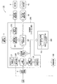
図4は本発明の第2実施例に係る指示計器装置の構成を示す図である。図4に示す指示計器装置1Aは、レブインジケータ機能を備えたエンジン回転数計(タコメータ)である。この指示計器装置1は、制御部(マイコン部)20と、補正データ記憶手段(EEPROM)30と、指示計器4と、指示計器駆動回路5と、表示部6と、表示部駆動回路7と、波形生成回路8と、設定操作部9とからなる。補正データ記憶手段(EEPROM)30には、エンジン回転数の測定値を補正するための測定値補正係数データ301、および、指示計器4の指示値のずれを補正するための指示値補正データ302がそれぞれ格納されている。制御部(マイコン部)20は、セラミック振動子21と、クロック発生回路220と、エンジン回転数測定手段23と、測定値補正手段230と、指示角度設定手段(指示値補正手段)240と、指示計器駆動信号生成手段25と、回転数設定手段260と、表示制御手段270と、調整制御手段280と、シリアル通信手段29等を備える。
FIG. 4 is a diagram showing the configuration of the indicating instrument device according to the second embodiment of the present invention. The indicating instrument device 1A shown in FIG. 4 is an engine speed meter (tachometer) having a rev indicator function. The indicating
クロック発生回路220は、セラミック振動子21によって定まる周波数のシステムクロック(マイコン駆動用クロック)を生成するとともに、システムクロックを所定の分周数で分周した基準クロックを生成する。クロック発生回路220は、システムクロック(マイコン駆動用クロック)または基準クロックの出力端子を備えている。
The
エンジン回転数測定手段23は、波形整形された入力信号の周期または周波数を基準クロックに基づいて計測し、計測した周期または周波数に基づいてエンジン回転数を演算し、所定回数のエンジン回転数測定値の平均値を求めて出力する。このエンジン回転数測定手段23は、予め設定した基準クロックの基準周期に基づいて入力信号の周期または周波数を計測する。ここで、基準周期とはセラミック振動子21の公称周波数に対応して設定される周期である。したがって、セラミック振動子21の周波数(実際の発振周波数)が公称周波数と一致している場合には、入力信号の周期または周波数が正確に測定され、正確なエンジン回転数が求まる。セラミック振動子21の周波数(実際の発振周波数)が公称周波数に対してずれている場合は、そのずれ量に応じた計測誤差が生ずる。例えば、セラミック振動子21の周波数(実際の発振周波数)が公称値に対して例えば5%低い場合には、測定されたエンジン回転数は実際の回転数よりも5%低くなる。
The engine speed measuring means 23 measures the period or frequency of the waveform-shaped input signal based on the reference clock, calculates the engine speed based on the measured period or frequency, and measures the engine speed measured value a predetermined number of times. Find the average value of and output. The engine speed measuring means 23 measures the cycle or frequency of the input signal based on a preset reference cycle of the reference clock. Here, the reference period is a period set corresponding to the nominal frequency of the
測定値補正手段230は、上記の計測誤差を補正して正確なエンジン回転数を出力する。この測定値補正手段230は、補正データ記憶手段(EEPROM)30に格納されている測定値補正係数データ301を読み出し、読出した測定値補正係数データ301に基づいてエンジン回転数の測定値を補正する。測定値補正係数として、セラミック振動子21の公称周波数と実際の発振周波数との比が設定されている。補正されたエンジン回転数の測定値は、指示角度設定手段(指示値補正手段)240および表示制御手段270に供給される。
The measured value correcting means 230 corrects the above measurement error and outputs an accurate engine speed. The measured value correction means 230 reads the measured value
指示角度設定手段(指示値補正手段)240は、測定値補正手段230によって補正されたエンジン回転数を入力として指示角度を求めて出力する。指示角度設定手段(指示値補正手段)240は、エンジン回転数と指示角度との関係が予め登録された指示角度テーブル(図示しない)および補正データ記憶手段(EEPROM)30に格納されている指示値補正データ302を参照して指示角度を演算する。指示角度テーブルは、図示しないROMに格納されている。この指示角度テーブルには、複数のエンジン回転数に対して指示角度がそれぞれ設定されている。指示角度テーブルには、エンジン回転数−指示角度の代表的な特性が格納されている。補正データ記憶手段(EEPROM)30内の指示値補正データ格納領域には、指示計器装置1Aの製造時等に図4において仮想線で示す調整装置100等を用いて指針の指示値を調整した際の補正データが格納されている。図示しない指示角度テーブルおよび補正データ記憶手段(EEPROM)30には、複数のポイントについてデータが設定されている。指示角度設定手段(指示値補正手段)240は、複数のポイント間を直線補間することで、エンジン回転数に対する指示角度を演算によって求める。求められた指示角度は、指示計器駆動信号生成手段25に供給される。
The indicated angle setting means (indicated value correcting means) 240 obtains and outputs the indicated angle with the engine speed corrected by the measured value correcting means 230 as an input. The indicated angle setting means (indicated value correcting means) 240 is an indicated value stored in an indicated angle table (not shown) and correction data storage means (EEPROM) 30 in which the relationship between the engine speed and the indicated angle is registered in advance. The indicated angle is calculated with reference to the
指示計器4に交差コイル式のものを用いる場合、指示計器駆動信号生成手段25は、指示角度設定手段(指示値補正手段)24によって設定された指示角度に基づいてサイン波特性のPWM信号およびコサイン波特性のPWM信号をそれぞれ生成して出力する。各PWM信号は、指示計器駆動回路5によって電力増幅され、指示計器(交差コイル式計器)の各コイルに供給される。これにより、交差コイル式計器内の回転磁石が回動され、回転磁石に連結された指針によってエンジン回転数が指示される。指示計器駆動信号生成手段25は、図示しないROMに予め格納されている指示角度−デューティ比変換テーブルを参照してデューティ比および駆動極性を求め、求めたデューティ比および駆動極性のPWM信号を生成する。
When the crossed coil type is used for the indicating instrument 4, the indicating instrument drive signal generating means 25 generates a sine wave characteristic PWM signal based on the indicated angle set by the indicated angle setting means (indicated value correcting means) 24. Generate and output cosine wave characteristic PWM signals. Each PWM signal is power-amplified by the indicating
指示計器4にステッピングモータ式のものを用いる場合、指示計器駆動信号生成手段25は、指示角度設定手段(指示値補正手段)24によって設定された指示角度に基づいてステッピングモータ式指示計器を駆動する信号(指示角度に対応した電気角の信号)を生成して出力する。ステッピングモータ式指示計器を駆動する信号は、指示計器駆動回路5によって電力増幅され、ステッピングモータ式計器の各コイルに供給される。これにより、ステッピングモータ式指示計器の指針が駆動され、エンジン回転数が指示される。指示計器駆動信号生成手段25は、図示しないROMに予め格納されている指示角度−電気角変換テーブルを参照してステッピングモータ式指示計器の各相コイルへ供給する信号を生成する。
When a stepping motor type is used for the indicating instrument 4, the indicating instrument drive signal generating means 25 drives the stepping motor type indicating instrument based on the indicated angle set by the indicated angle setting means (indicated value correcting means) 24. A signal (electrical angle signal corresponding to the indicated angle) is generated and output. The signal for driving the stepping motor type indicating instrument is power amplified by the indicating
回転数設定手段260は、図示しないエンジンが停止している状態(エンジン回転数がゼロの状態または入力信号が入力されていない状態)で、設定操作部9の押しボタンスイッチ等が操作されると、エンジン回転数が所定の時間間隔で段階的に増加するレブインジケータ設定用データを指示角度設定手段(指示値補正手段)240へ供給する。例えば、0.5秒間隔でエンジン回転数が0,250,500,……と250rpm毎に増加するレブインジケータ設定用データを出力する。これにより、指示計器4の指針が250rpmステップで回転される。運転者等は、指針の指示値が所望の回転数に達した時点で、設定操作部9を再度操作する。回転数設定手段260は、設定操作部9が再度操作されると、その操作時点での回転数を所定時間保持するとともに、その回転数を図示しないRAMまたは補正データ記憶手段(EEPROM)30等に記憶させた後に、レブインジケータ設定用データの出力を停止する。なお、レブインジケータ設定用データの出力を停止するのではなく、操作時点での回転数を所定時間保持した後に再度指針を回動させることで、複数の回転数を設定できるようにしてもよい。
The rotation speed setting means 260 is operated when a push button switch or the like of the
回転数設定手段260は、図示しないエンジンが始動されると、設定されたエンジン回転数を表示制御手段270に供給する。表示制御手段270は、設定されたエンジン回転数と測定値補正手段230から出力されるエンジン回転数とを比較し、エンジン回転数が設定された回転数以上である場合には、報知信号を表示駆動回路7に出力する。これにより、表示駆動回路7を介して表示部6内の可視表示器や可聴表示器が駆動され、光や音によって設定回転数に達したことが報知される。なお、表示制御手段270は、エンジン回転数が設定回転数よりも所定値だけ低い時点で、報知信号を断続させ、ランプの点滅やブザー音の断続によってエンジン回転数が設定回転数に近づいていることを表示させるようにしてもよい。
The engine speed setting means 260 supplies the set engine speed to the display control means 270 when an engine (not shown) is started. The display control means 270 compares the set engine speed with the engine speed output from the measured value correction means 230, and displays a notification signal when the engine speed is equal to or higher than the set speed. Output to the
次に、指示計器装置1Aの調整について説明する。調整装置100は、指示計器装置1Aに校正用入力信号を供給するとともに、制御部(マイコン部)20内のシリアル通信手段29を介して調整手段280とデータ通信を行なうことで、指針の指示値の調整を行なって、指示値補正データ302の設定を行なう。調整装置100は、指示計器4の表示面(指針および目盛)を撮像する撮像手段と、その撮像画像を解析して指針の指示値を読み取る画像解析手段と、校正用入力信号を生成して供給する手段と、クロック発生回路220で生成したシステムクロック(マイコン駆動用クロック)または基準クロックの周波数を測定する周波数測定手段と、予め登録された制御プログラムに基づいて指示計器装置1の調整および各補正データ301,302の設定を自動で行なう自動調整手段等を備える。なお、自動調整を行なわない場合は、撮像手段、画像解析手段等は不要である。
Next, adjustment of the indicating instrument device 1A will be described. The adjusting device 100 supplies a calibration input signal to the indicating instrument device 1A, and performs data communication with the adjusting
調整装置100は、最初に調整制御手段280に対して調整モード(動作モード)を指定した後に、一連の調整を行なう。調整制御手段280は、調整装置100から供給される各種コマンドおよびデータに基づいて所定の動作を行なう。 The adjustment device 100 first designates an adjustment mode (operation mode) to the adjustment control means 280 and then performs a series of adjustments. The adjustment control means 280 performs a predetermined operation based on various commands and data supplied from the adjustment device 100.
調整制御手段280は、調整装置100によって指示値補正モードが指定されると、調整装置100から供給されるエンジン回転数データを指示角度設定手段(指示値補正手段)240に供給する。これにより、調整装置100から供給されるエンジン回転数データに基づいて指針が回動される。調整装置100は、指定したエンジン回転数と指針の指示値とを比較し、指示値にずれが生じている場合には、そのずれ方向に応じて指示角度を最小ステップで増加または減少するコマンドを調整制御手段280に供給する。これにより、指針の指示値が補正される。調整装置100は、指示値のずれが許容範囲内となった時点で、そのときの指示角度の補正値を調整制御手段280を介して補正データ記憶手段(EEPROM)30内の指示値補正データ格納領域に書き込ませる。ここで、補正値はエンジン回転数との対応を付けて記憶される。調整装置100は、複数のエンジン回転数について補正値をそれぞれもとめ、求めた複数の補正値をエンジン回転数との対応を付けて指示値補正データ格納領域に書き込ませる。これにより、指示計器4の指示誤差が指示計器駆動回路5の駆動特性を含めて補正される。
When the instruction value correction mode is designated by the adjustment device 100, the adjustment control means 280 supplies the engine speed data supplied from the adjustment device 100 to the instruction angle setting means (instruction value correction means) 240. Thereby, the pointer is rotated based on the engine speed data supplied from the adjustment device 100. The adjusting device 100 compares the designated engine speed with the indicated value of the pointer, and if there is a deviation in the indicated value, a command for increasing or decreasing the indicated angle in a minimum step according to the deviation direction. This is supplied to the adjustment control means 280. Thereby, the indicated value of the pointer is corrected. When the deviation of the indicated value falls within the allowable range, the adjustment apparatus 100 stores the indicated value correction data in the correction data storage means (EEPROM) 30 via the adjustment control means 280 at that time. Let the area write. Here, the correction value is stored in association with the engine speed. The adjustment device 100 obtains correction values for a plurality of engine speeds, and writes the obtained correction values in the instruction value correction data storage area in association with the engine speeds. Thereby, the indication error of the indicating instrument 4 is corrected including the driving characteristics of the indicating
調整装置100は、クロック発生回路220で生成したシステムクロック(マイコン駆動用クロック)または基準クロックの周波数を測定し、公称周波数(f0)と実際の発振周波数(f)との比(f0/f)を求める。調整装置100は、求めた比(f0/f)の値を測定補正係数データとし、この測定補正係数データを調整制御手段280を介して補正データ記憶手段(EEPROM)30内の測定値補正係数データ格納領域に書き込ませる。
The adjusting device 100 measures the frequency of the system clock (microcomputer driving clock) or the reference clock generated by the
なお、調整装置100は、調整制御手段280を介して補正データ記憶手段(EEPROM)30に記憶されている各補正データ301,302を読み出すことができる。これにより、各補正データ301,302をチェックできる。また、指示計器装置1Aとの対応を付けて各補正データを保存・管理することもできる。
The adjustment apparatus 100 can read out the
図4に示す指示計器装置1Aは、基準クロックの周波数のずれに伴って生ずるエンジン回転数測定値の誤差を測定値補正手段230によって補正するので、正確なエンジン回転数を測定することができる。これにより、高精度の指示ができる。 Since the indicating instrument device 1A shown in FIG. 4 corrects the error of the engine speed measurement value caused by the deviation of the frequency of the reference clock by the measurement value correcting means 230, it can measure the accurate engine speed. Thereby, a highly accurate instruction can be performed.
本発明に係る指示計器装置は、デジタル表示式のエンジン回転数計や車速計にも適用することができる。 The indicating instrument device according to the present invention can be applied to a digital display type engine speed meter and vehicle speed meter.
図5は本発明の第3実施例に係る指示計器装置の構成を示す図である。図5に示す指示計器装置1Bは、エンジン回転数または車速をデジタル表示するデジタル表示部40と、デジタル表示部駆動回路50を備える。制御部(マイコン部)200内の表示データ切替手段201は、報知値の設定を行なうときだけ報知値設定手段261から出力される報知値設定データをデジタル表示部駆動回路50へ供給し、それ以外のときは測定値補正手段232から出力される測定値補正データをデジタル表示部駆動回路50へ供給する。周期測定手段231は、入力信号の周期を測定して平均値を求め、その平均値に対応したエンジン回転数または車速の測定値データを出力する。この測定値データにはクロック周波数のずれに伴う誤差が含まれている。測定値補正手段232は、補正データ記憶手段(EEPROM)300に記憶されている測定補正係数データ301を読み出し、読み出した測定補正係数データ301に基づいて測定値データを補正して、測定値補正データを出力する。
FIG. 5 is a diagram showing the configuration of the indicating instrument device according to the third embodiment of the present invention. The indicating
調整装置100は、クロック発生回路220で生成したシステムクロック(マイコン駆動用クロック)または基準クロックの周波数を測定し、公称周波数(f0)と実際の発振周波数(f)との比(f0/f)を求める。調整装置100は、求めた比(f0/f)の値を測定補正係数データとし、この測定補正係数データを調整制御手段280を介して補正データ記憶手段(EEPROM)300内の測定値補正係数データ格納領域に書き込ませる。
The adjusting device 100 measures the frequency of the system clock (microcomputer driving clock) or the reference clock generated by the
図5に示す指示計器装置1Bは、基準クロックの周波数のずれに伴って生ずるエンジン回転数や車速の測定値の誤差を測定値補正手段232によって補正するので、正確なエンジン回転数や車速を測定することができる。これにより、高精度の指示ができる。
Since the indicating
1,1A,1B 指示計器装置
2,20,200 制御部(マイコン部)
3,30,300 補正データ記憶手段(EEPROM)
4 指示計器
10,100 調整装置
21 セラミック振動子
22,220 クロック発生回路
23 エンジン回転数測定手段
24,240 指示角度設定手段(指示値補正手段)
28,280 調整制御手段
31 タコメータ用補正データ
32 レブインジケータ設定用補正データ
40 デジタル表示部
230,232 測定値補正手段
231 周期測定手段
301 測定値補正係数データ
302 指示値補正データ
1,1A, 1B
3, 30, 300 Correction data storage means (EEPROM)
4 indicating instrument 10, 100
28,280 Adjustment control means 31
Claims (3)
前記エンジン回転数に応じた指示値のずれを補正するためのタコメータ用補正データを記憶する手段と、
レブインジケータの回転数を設定するために前記指示計器を駆動する際に、回転数に応じた指示値のずれを補正するためのレブインジケータ設定用補正データを記憶する手段と、
前記エンジン回転数を表示する場合には前記タコメータ用補正データに基づいて指示値の補正を行なうとともに、前記レブインジケータの回転数を設定するために指示計器を駆動する場合には前記レブインジケータ設定用補正データに基づいて指示値の補正を行なう指示値補正手段とを備えることを特徴とする指示計器装置。 An indicating instrument device for determining the engine speed by measuring a cycle or frequency of an input signal corresponding to the engine speed, and driving an indicating instrument so that a pointer indicates an instruction value corresponding to the engine speed. ,
Means for storing correction data for a tachometer for correcting a deviation of an instruction value according to the engine speed;
Means for storing rev indicator setting correction data for correcting a deviation of the indicated value according to the rotational speed when driving the indicator instrument to set the rotational speed of the rev indicator;
When displaying the engine speed, the indication value is corrected based on the tachometer correction data, and when the indicator instrument is driven to set the rotation speed of the rev indicator, the rev indicator is set. An indicator instrument device comprising: indicator value correcting means for correcting the indicator value based on the correction data.
基準とするクロック周波数と実際のクロック周波数とのずれによって生ずるエンジン回転数の測定値のずれを補正する測定値補正手段を備えることを特徴とする指示計器装置。 An indicating instrument device for determining the engine speed by measuring a cycle or frequency of an input signal corresponding to the engine speed, and displaying the determined engine speed,
An indicator instrument device comprising: a measured value correcting means for correcting a deviation in a measured value of an engine speed caused by a deviation between a reference clock frequency and an actual clock frequency.
基準とするクロック周波数と実際のクロック周波数とのずれによって生ずる測定値のずれを補正する測定値補正手段を備えることを特徴とする指示計器装置。 An indicating instrument device for obtaining a measurement value of the measurement object by measuring a period or a frequency of an input signal to be measured, and displaying the obtained measurement value,
An indicating instrument device comprising measurement value correcting means for correcting a deviation of a measurement value caused by a deviation between a reference clock frequency and an actual clock frequency.
Priority Applications (1)
| Application Number | Priority Date | Filing Date | Title |
|---|---|---|---|
| JP2004108631A JP2005291976A (en) | 2004-04-01 | 2004-04-01 | Indicating instrument system |
Applications Claiming Priority (1)
| Application Number | Priority Date | Filing Date | Title |
|---|---|---|---|
| JP2004108631A JP2005291976A (en) | 2004-04-01 | 2004-04-01 | Indicating instrument system |
Publications (1)
| Publication Number | Publication Date |
|---|---|
| JP2005291976A true JP2005291976A (en) | 2005-10-20 |
Family
ID=35325060
Family Applications (1)
| Application Number | Title | Priority Date | Filing Date |
|---|---|---|---|
| JP2004108631A Pending JP2005291976A (en) | 2004-04-01 | 2004-04-01 | Indicating instrument system |
Country Status (1)
| Country | Link |
|---|---|
| JP (1) | JP2005291976A (en) |
Cited By (1)
| Publication number | Priority date | Publication date | Assignee | Title |
|---|---|---|---|---|
| CN106885923A (en) * | 2017-03-22 | 2017-06-23 | 中国人民解放军海军航空工程学院 | A kind of general rotation speed source suitable for aircraft engine |
-
2004
- 2004-04-01 JP JP2004108631A patent/JP2005291976A/en active Pending
Cited By (1)
| Publication number | Priority date | Publication date | Assignee | Title |
|---|---|---|---|---|
| CN106885923A (en) * | 2017-03-22 | 2017-06-23 | 中国人民解放军海军航空工程学院 | A kind of general rotation speed source suitable for aircraft engine |
Similar Documents
| Publication | Publication Date | Title |
|---|---|---|
| JP5480385B2 (en) | Display method for timer and semitone gradation instrument | |
| JP3653746B2 (en) | Electronic clock | |
| US8056388B2 (en) | Pointer instrument | |
| JPH07239716A (en) | Position detection device, position detection device with correction function, position detection method, and position detection device correction method | |
| US20140219068A1 (en) | Analog electronic timepiece | |
| JP7000263B2 (en) | Initial setting method and initial setting device | |
| JP4930919B2 (en) | Rotational position signal processor | |
| JP2005291976A (en) | Indicating instrument system | |
| CN101932907A (en) | Method for operating a display device driven by at least one stepper motor | |
| US6170323B1 (en) | Self-diagnosis apparatus for vehicle meters and method starting a self-diagnosis mode for vehicle meters | |
| JP2000018975A (en) | Device for stepping motor type instrument | |
| JP2564887B2 (en) | Measurement signal correction circuit | |
| US6310834B1 (en) | Electronic apparatus with ultrasonic motor as driving source | |
| CN116678302B (en) | Micrometer-based calibration method for swing sensor | |
| JP2021071444A (en) | Rotation angle detector | |
| JPH1048012A (en) | Electronic water meter | |
| JP4805543B2 (en) | Crossed coil instrument with predetermined characteristics | |
| JP4732564B2 (en) | Angle measuring device for surveying instrument equipped with absolute encoder | |
| JP2002054923A (en) | Angle measuring instrument of surveying device | |
| KR101034691B1 (en) | Speed detector of digital governor using magnetic pickup sensor | |
| JPH07107925B2 (en) | Trimming device | |
| JP2555389Y2 (en) | Pointed position correction circuit for cross-coil instrument | |
| JPH06729Y2 (en) | Indicator | |
| JPH0625783U (en) | Electronic watch with meter function | |
| JPS62101123A (en) | Pulse type rotation speed measuring device |
Legal Events
| Date | Code | Title | Description |
|---|---|---|---|
| A621 | Written request for application examination |
Free format text: JAPANESE INTERMEDIATE CODE: A621 Effective date: 20070329 |
|
| A977 | Report on retrieval |
Free format text: JAPANESE INTERMEDIATE CODE: A971007 Effective date: 20090728 |
|
| A131 | Notification of reasons for refusal |
Free format text: JAPANESE INTERMEDIATE CODE: A131 Effective date: 20090901 |
|
| A02 | Decision of refusal |
Free format text: JAPANESE INTERMEDIATE CODE: A02 Effective date: 20100106 |