JP2005291903A - Hydrophone for underwater geophone, and multipoint observation underwater geophone - Google Patents
Hydrophone for underwater geophone, and multipoint observation underwater geophone Download PDFInfo
- Publication number
- JP2005291903A JP2005291903A JP2004106855A JP2004106855A JP2005291903A JP 2005291903 A JP2005291903 A JP 2005291903A JP 2004106855 A JP2004106855 A JP 2004106855A JP 2004106855 A JP2004106855 A JP 2004106855A JP 2005291903 A JP2005291903 A JP 2005291903A
- Authority
- JP
- Japan
- Prior art keywords
- geophone
- wave
- underwater
- hydrophone
- observation
- Prior art date
- Legal status (The legal status is an assumption and is not a legal conclusion. Google has not performed a legal analysis and makes no representation as to the accuracy of the status listed.)
- Pending
Links
- 230000035945 sensitivity Effects 0.000 claims abstract description 32
- 239000000463 material Substances 0.000 claims abstract description 11
- 238000010586 diagram Methods 0.000 claims description 11
- 238000000034 method Methods 0.000 claims description 11
- 238000012545 processing Methods 0.000 claims description 7
- 239000007788 liquid Substances 0.000 claims description 4
- 230000005855 radiation Effects 0.000 claims description 4
- 238000005259 measurement Methods 0.000 description 10
- 230000006835 compression Effects 0.000 description 6
- 238000007906 compression Methods 0.000 description 6
- 230000001902 propagating effect Effects 0.000 description 5
- 238000004458 analytical method Methods 0.000 description 4
- 239000000919 ceramic Substances 0.000 description 4
- 239000007789 gas Substances 0.000 description 4
- 238000003780 insertion Methods 0.000 description 3
- 230000037431 insertion Effects 0.000 description 3
- 238000005192 partition Methods 0.000 description 3
- 239000011435 rock Substances 0.000 description 3
- XLYOFNOQVPJJNP-UHFFFAOYSA-N water Substances O XLYOFNOQVPJJNP-UHFFFAOYSA-N 0.000 description 3
- 230000001133 acceleration Effects 0.000 description 2
- 230000007423 decrease Effects 0.000 description 2
- 230000000694 effects Effects 0.000 description 2
- 238000011156 evaluation Methods 0.000 description 2
- 238000000605 extraction Methods 0.000 description 2
- 230000010355 oscillation Effects 0.000 description 2
- 238000007789 sealing Methods 0.000 description 2
- IJGRMHOSHXDMSA-UHFFFAOYSA-N Atomic nitrogen Chemical compound N#N IJGRMHOSHXDMSA-UHFFFAOYSA-N 0.000 description 1
- 230000015572 biosynthetic process Effects 0.000 description 1
- 230000000903 blocking effect Effects 0.000 description 1
- 238000006243 chemical reaction Methods 0.000 description 1
- 229910001873 dinitrogen Inorganic materials 0.000 description 1
- 238000011065 in-situ storage Methods 0.000 description 1
- 238000004519 manufacturing process Methods 0.000 description 1
- 238000000691 measurement method Methods 0.000 description 1
- 238000003825 pressing Methods 0.000 description 1
- 238000003672 processing method Methods 0.000 description 1
- 238000010008 shearing Methods 0.000 description 1
- 239000002689 soil Substances 0.000 description 1
- 238000012360 testing method Methods 0.000 description 1
Images


Landscapes
- Measurement Of Mechanical Vibrations Or Ultrasonic Waves (AREA)
- Geophysics And Detection Of Objects (AREA)
- Measurement Of Velocity Or Position Using Acoustic Or Ultrasonic Waves (AREA)
Abstract
Description
この発明は、地盤に穿設されたボーリング孔内において、地盤を伝播する地震波を効率
的且つ的確に地震波を観測する装置に係り、より詳しくは、水中受振器用ハイドロホンと
、該ハイドロホンを組み立てて製作した水中受振器に関する。
地震波は、波動性状の異なる種類のものが存在し、伝播過程で、反射、屈折、回折また
は波動の変換がおこる。このため地盤内には多様な地震波が存在する。地震波の特定の波
動を観測するためには、波動性状や入射方向に適した観測方法で行う必要がある。
この発明の地震波を観測する装置の主な用途としては、以下のものがある。
先ず、振源を地表あるいは地中に設け、地震波の到達時間からP波またはS波の地盤の
伝播速度を求める速度検層がある。PS速度検層で得られる地盤のせん断波(S波)及び
圧縮波(P波)の伝播速度は、土木工学や岩盤力学における土質、岩質の評価、特に地震
時の動的特性の解析・評価に不可欠な情報である。
同様に振源を地表あるいは地中に設け、ボーリング孔内でP波またはS波を観測し、地
震波の処理を行って地盤内の地震波の伝播状況を求め、土木地質や資源探査で多く用いら
れている反射法地震探査の解析資料とするVSP(Vertical Seismic Profile)法がある
。PS検層は、初動を読取り伝播速度を算定するのに対し、VSPは、観測した地震波形
から地盤の反射状態を把握するものである。
ボーリング孔内を伝播するチューブ・ウェーブは、地盤内の剛性率や透水係数の算定に
研究されている。しかしながら、チューブ・ウェーブとS波とは伝播速度が比較的類似し
ているため、S波の観測にはチューブ・ウェーブが妨害波となり、逆にチューブ・ウェー
ブの観測には、S波が妨害波となる。したがって、チューブ・ウェーブとS波とを明確に
区分することが重要である。
The present invention relates to an apparatus for efficiently and accurately observing seismic waves propagating in the ground in a borehole drilled in the ground, and more particularly, assembling the hydrophone for an underwater geophone and the hydrophone. The underwater geophone manufactured by
There are different types of seismic waves, and reflection, refraction, diffraction or wave conversion occurs in the propagation process. For this reason, there are various seismic waves in the ground. In order to observe a specific wave of a seismic wave, it is necessary to use an observation method suitable for the wave properties and the incident direction.
The main applications of the apparatus for observing seismic waves of the present invention are as follows.
First, there is a velocity logging in which a vibration source is provided on the ground surface or in the ground, and the propagation speed of the P wave or S wave ground is determined from the arrival time of the seismic wave. The propagation velocity of the shear wave (S wave) and compression wave (P wave) of the ground obtained by PS velocity logging is the evaluation of soil and rock quality in civil engineering and rock mechanics, especially analysis of dynamic characteristics during earthquakes. This information is essential for evaluation.
In the same way, a source is installed on the ground surface or in the ground, P waves or S waves are observed in the borehole, seismic wave processing is performed to determine the propagation status of seismic waves in the ground, and it is often used in civil engineering geology and resource exploration. There is a VSE (Vertical Seismic Profile) method used as analysis data for reflection seismic surveys. The PS logging reads the initial motion and calculates the propagation velocity, while the VSP grasps the ground reflection state from the observed seismic waveform.
Tube waves propagating in boreholes are being studied for calculating the rigidity and hydraulic conductivity in the ground. However, since tube waves and S waves have relatively similar propagation velocities, tube waves are disturbing waves for observing S waves, and conversely, S waves are disturbing waves for observing tube waves. It becomes. Therefore, it is important to clearly distinguish tube waves and S waves.
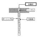
図3に示すように、水等の液体を充填したボーリング孔内に電磁型受振器を設置し、地
表付近で発振した地震波を地盤内で観測する手法は、PS波の速度検層やVSP法で用い
られる。
P波のみの観測では、ハイドロホン単体あるいは電磁型受振素子単体を用いることがあ
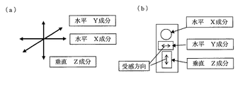
るが、PS検層など、P波とS波を識別して観測する場合には、受振器には、図4(a)
に示すようにX,Y,Zの3方向に、図4(b)の如く水平成分2個、垂直成分1個の、
合計3個の電磁型受振素子を3段に組み込んだ3成分受振器と呼ばれる地震計が用いられ
る。
S波は、地震波の進行方向に対し直角(せん断的)に振動し、P波は、地震波の進行方
向(圧縮−引張り)に振動する。この波動現象の差異があるため、P波とSとを区別して
観測する場合には、3成分受振器を用いて観測する。
S波の波動を同定するため、地表に板を設置し、板の端部を順方向と逆方向の2回打撃
した記録を各水平成分(X成分,Y成分)で取得し、その波動の反転を確認して同定する
。
P波では、通常地表で起振された地震波は、ほぼ鉛直下方に伝播するため、垂直成分(
Z成分)で観測する。
As shown in FIG. 3, an electromagnetic geophone is installed in a boring hole filled with a liquid such as water, and the method of observing seismic waves oscillating near the ground surface in the ground is the velocity logging of PS waves or the VSP method. Used in
In the observation of only the P wave, the hydrophone alone or the electromagnetic receiving element alone may be used. However, when the P wave and the S wave are discriminated and observed, such as PS logging, the geophone is shown in FIG. (A)
As shown in FIG. 4, two horizontal components and one vertical component as shown in FIG.
A seismometer called a three-component geophone that incorporates a total of three electromagnetic transducers in three stages is used.
The S wave oscillates at right angles (shearing) to the traveling direction of the seismic wave, and the P wave oscillates in the traveling direction (compression-tension) of the seismic wave. Due to the difference in the wave phenomenon, when the P wave and S are observed separately, the observation is performed using a three-component geophone.
In order to identify the wave of the S wave, a plate was installed on the ground surface, and a record in which the edge of the plate was hit twice in the forward and reverse directions was acquired for each horizontal component (X component, Y component). Confirm the inversion and identify.
In P waves, seismic waves oscillated on the normal ground surface propagate almost vertically downward, so the vertical component (
Observe with Z component).
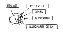
図5に見るようにボーリング孔壁に固定された受振器は、ボーリング孔壁の周方向にお
ける1点の振動を観測していることになる。ボーリング孔内には、孔内を伝播する特殊な
地震波が存在する。
このため、3成分受振器による孔壁の周方向における1点の観測では、異なる振動性状
の波動が、同一の振動現象として観測されて、これら異なる振動性状の波動を区別できな
いことがある。
このように地震波の観測においては、確実に目的とする地震波を抽出・観測するための
手法の確立が望まれているところである。
As shown in FIG. 5, the geophone fixed to the borehole wall observes one point of vibration in the circumferential direction of the borehole wall. In the borehole, there is a special seismic wave that propagates through the hole.
For this reason, in the observation of one point in the circumferential direction of the hole wall by the three-component geophone, waves having different vibration properties may be observed as the same vibration phenomenon, and the waves having different vibration properties may not be distinguished.
Thus, in the observation of seismic waves, it is desired to establish a method for reliably extracting and observing the desired seismic waves.
また、電磁型受振素子を用いた3成分受振器は、ボーリング孔壁に固定する必要があり
、この固定方式としては従来、アームを開く機械式や風船を膨張させるガス圧式のものが
ある。
ガス圧式のものを用いた場合、ある計測深度において3成分受振器と一体化された孔壁
固定装置の膨張具に窒素ガスを充填して膨らませ、当該深度における計測を終了した後、
窒素ガスを孔壁固定装置から排除して次の計測点に至るまで受振器を降下させて、上記と
同様の固定作業、観測作業、解除作業、深度変更作業を繰り返している。
このように、従来の地震波観測において、3成分受振器を用いた計測の作業性は極めて
悪い。特に大深度の計測には大きな課題となっている。
In addition, a three-component geophone using an electromagnetic type geophone needs to be fixed to the borehole wall. Conventionally, there are a mechanical type that opens an arm and a gas pressure type that expands a balloon.
When using a gas pressure type, inflate the inflatable device of the hole wall fixing device integrated with the three-component geophone at a certain measurement depth and inflate it, and after the measurement at that depth is completed,
Nitrogen gas is removed from the hole wall fixing device and the geophone is moved down to the next measurement point, and the same fixing work, observation work, releasing work, and depth changing work are repeated.
Thus, in the conventional seismic wave observation, the workability of measurement using a three-component geophone is extremely poor. This is a big problem especially for measurement at a large depth.
さらに、この受振器は電磁型受振素子を用いていることから地震波の信号出力は、速度
型振幅であることから、S波速度が高くなると受振感度が小さくなり、また、高周波数領
域の感度も小さくなる、という重大な問題がある。
さらにまた、所定間隔で複数の3方向受振器を備えた、いわゆる多連型受振器にしよう
とすると、受振器をボーリング孔壁に固定するための装置を各受振器毎に設ける必要があ
ることから、特にガス圧式の固定装置にあってはガス圧送用配管が錯綜して、装置全体が
複雑な構成となり、また操作上も煩雑となることから、多連型のものとすることも困難で
ある。
Furthermore, when trying to make a so-called multiple-type geophone with a plurality of three-way geophones at a predetermined interval, a device for fixing the geophone to the borehole wall needs to be provided for each geophone. Therefore, especially in the case of gas pressure type fixing devices, the piping for gas pressure feeding is complicated, and the entire device has a complicated configuration and is complicated in operation. is there.
他方、本発明者は、軟弱地盤から硬岩地盤までの広範囲にわたってボーリング孔内のS
波、P波の速度を正確に計測できる計測方法を提供することを目的として、図7に示され
るような、1つの発振器53と互いに一定の距離を隔てて設けられた2つの受振器54、
55を有しケーブル51に吊り下げられたゾンデ52を用いて地層検層におけるせん断波
の速度を計測する方法において、一対の矩形バイモルフ型圧電セラミックからなる発振器
53によって一方向のせん断波を発振し、該せん断波を一対の円筒型圧電セラミックから
なる前記一方の受振器54によって受振し、該受振器54の各円筒型圧電セラミックの振
動波形の差を求めて記録し、次に前記発振器53によって逆方向のせん断波を発振し、該
せん断波を前記と同様に受振器54の各円筒型圧電セラミックの振動波形の差を求めて記
録し、上記2つの記録を用いて位相の反転からせん断波の初動時間を計測し、さらに他方
の受振器55においても同様にせん断波の初動時間を計測し、前記2つの受振器54、5
5のそれぞれの初動の時間差から地層のせん断波速度を計測する方法を提案したものであ
る。
For the purpose of providing a measurement method capable of accurately measuring the velocity of waves and P waves, as shown in FIG. 7, two
In the method of measuring the shear wave velocity in the geological logging using the
The method of measuring the shear wave velocity of the formation from the time difference of each initial motion of 5 is proposed.
このPS速度検層装置の受振器は、本発明と同じく圧電素子を用いているが、ボーリン
グ孔内で発振した地震波をボーリング孔内で受振することを前提として、ゾンデ内の振源
の発振方向に合わせて単一の受振方向に固定しており、地表又は地中で発振したP波、S
波の地震波、特に水平軸XY2方向に起振された波動を受振するものではない。
The PS velocity logging device uses a piezoelectric element as in the present invention. However, on the assumption that the seismic wave oscillated in the borehole is received in the borehole, the oscillation direction of the source in the sonde P wave oscillated in the ground surface or in the ground, S
It does not receive the seismic waves of the waves, especially the waves oscillated in the direction of the horizontal axis XY2.
以上のように、上記第1の従来技術である3成分受振器では、該受振器が接触するボー
リング孔壁の1点で3方向の地震波を観測している。
前述したように、ボーリング孔内を伝播するチューブ・ウェーブは、P波・S波の観測に
障害となる。特にS波の観測では、振源の向きを順方向と逆方向とに変えて2回測定し、
波動の位相反転を確認して同定するが、孔壁周囲の1点で観測するため、チューブ・ウェ
ーブを完全に除去し、S波のみを分離することが難しいことがある。
以上の状況から、ボーリング孔内において、妨害波の影響を受けずに目的とする地震波
を的確に観測する手法の確立が望まれる。
また、3成分受振器を用いてボーリング孔内あるいは地盤内でPS波地震波を観測する
ときは、ある深度における観測点での測定終了後、次の深度における観測点での計測開始
までの間に種々の操作を必要とし、時間を要しひいてはコスト高となる。
さらに、この受振器は電磁型受振素子を用いているので、高いS波速度におけるS波の
感度が低下するばかりでなく、高周波数領域の感度も小さくなるという問題がある。更に
は、孔壁固定装置を3成分受振器と一体化した多連型受振器を製作することも容易ではな
く、また、ボーリング孔径は深さ方向に変化することがあり、各受振器を同時に同じ力で
固定することは難しい。
As described above, in the three-component geophone according to the first prior art, three directions of seismic waves are observed at one point on the borehole wall with which the geophone is in contact.
As described above, the tube wave propagating in the borehole becomes an obstacle to the observation of the P wave and the S wave. In particular, in S-wave observation, the source direction is changed twice between the forward and reverse directions.
Although the phase inversion of the wave is confirmed and identified, since observation is performed at one point around the hole wall, it may be difficult to completely remove the tube wave and separate only the S wave.
From the above situation, it is desirable to establish a method for accurately observing the target seismic wave without being affected by the disturbing wave in the borehole.
In addition, when observing PS wave seismic waves in a borehole or in the ground using a three-component geophone, after the measurement at the observation point at a certain depth is completed, the measurement is started at the observation point at the next depth. Various operations are required, which takes time and increases costs.
Furthermore, since this geophone uses an electromagnetic type geophone, there is a problem that not only the sensitivity of the S wave at a high S wave velocity is lowered, but also the sensitivity in the high frequency region is reduced. Furthermore, it is not easy to manufacture a multiple-type geophone with the hole wall fixing device integrated with a three-component geophone, and the borehole diameter may change in the depth direction. It is difficult to fix with the same force.
一方、上記第2の従来技術で用いられた受振器は、ボーリング孔内で発振した地震波を
孔内で受振することを前提として、ゾンデ内に設けられた発振器の発振方向に合わせて単
一の受振方向に固定されており、地表又は地中で発振したS波の地震波に対しては、水平
軸XY2方向の受振が必要であり、対応は不可能である。
On the other hand, the geophone used in the second prior art is based on the premise that the seismic wave oscillated in the borehole is received in the hole, and the single geophone is adapted to the oscillation direction of the oscillator provided in the sonde. The seismic wave of the S wave that is fixed in the receiving direction and oscillates on the ground surface or in the ground needs to be received in the horizontal axis XY2 direction and cannot be handled.
そこで本発明は、上記問題点を解決するために創出されたもので、従来の電磁型受振器
に代わる指向性のある水中受振器用ハイドロホンを提供することを目的とするものである
。
また、この水中受振器用ハイドロホンを組み立てて、複雑なボーリング孔壁の波動を、
同一深度のボーリング孔壁の周方向を多点で観測し、地震波の性状を明確に区分し、妨害
波の影響を小さくして、目的とする地震波を的確に抽出できる多点観測水中受振器を提供
することを目的とする。
さらに、観測作業を効率化、簡便化して計測コストを格段に低減することが可能な多点
観測水中受振器を提供することを目的としている。
Therefore, the present invention was created to solve the above-described problems, and an object thereof is to provide a hydrophone for an underwater geophone having directivity in place of a conventional electromagnetic geophone.
In addition, by assembling this hydrophone for underwater geophone,
A multipoint observation underwater geophone capable of accurately extracting the desired seismic wave by observing the circumferential direction of the borehole wall at the same depth at multiple points, clearly separating the properties of the seismic wave, reducing the influence of the disturbing wave The purpose is to provide.
It is another object of the present invention to provide an underwater geophone for multi-point observation that can greatly reduce the measurement cost by making the observation work more efficient and simple.
さらにまた、圧電素子を用いることにより、汎用性ある水中受振器とするとともに、受
振器の構造を簡素化し小型化して、さらに簡易に多連型の受振器を製造可能として、圧電
素子が有している潜在力を存分に活用した水中受振器を提供することを目的としている。
Furthermore, by using a piezoelectric element, the piezoelectric element has a versatile underwater geophone, and the structure of the geophone is simplified and miniaturized so that a multiple-type geophone can be easily manufactured. The purpose is to provide an underwater geophone that makes full use of its potential.
請求項1に係る発明は、ハイドロホンの周方向の一部を除く周囲を波動を遮断する遮蔽
材にて囲繞して、所定方向以外の方向の感度を有しない無感度領域と、前記ハイドロホン
の前記一部の周囲を露出して、所定方向の感度を有する有感度領域と、を具備した感度に
指向性が付与された水中受振器用ハイドロホンとした。
また、請求項2に係る発明は、ハイドロホンの周方向の一部を除く周囲を波動を遮断す
る遮蔽材にて囲繞して、所定方向以外の方向の感度を有しない無感度領域と、前記ハイド
ロホンの前記一部の周囲を露出して、所定方向の感度を有する有感度領域と、を具備した
感度に指向性が付与された水中受振器用ハイドロホンが、軸に沿って少なくとも4つ設け
られた多点観測水中受振器を、該水中受振器用ハイドロホンの有感度領域をボーリング孔
壁に対向するとともに、その周方向中央部と前記無感度領域の周方向中央部を、前記軸近
傍を中心として略等間隔に放射する偶数本の放射線上に位置するように配設した。
さらに、請求項3に係る発明は、前記多点観測水中受振器を、ケーブルに所定間隔を隔
てて複数個具備させて多連型多点観測水中受振器を構成した。
さらにまた、請求項4に係る発明は、前記請求項1乃至請求項3のいずれかに係る水中受
振器用ハイドロホンまたは多点観測水中受振器を用いて、所定の深度のボーリング孔壁の
少なくとも4点以上の周方向略等間隔の観測点において、該ボーリング孔壁の振動を液体
を介して互いに独立して受振し、受振した振動を観測点毎に電気信号に変換して出力し、
出力された信号を個別に観測し、あるいは加算、減算などの処理または選抜処理すること
により、地盤の所定の振動を解析することとした。
According to the first aspect of the present invention, the periphery of the hydrophone except for a part in the circumferential direction is surrounded by a shielding material that blocks the wave, and the insensitive region having no sensitivity in a direction other than a predetermined direction is provided. And a sensitive region having a sensitivity in a predetermined direction by exposing the periphery of the part of the submersible hydrophone for an underwater geophone.
Further, the invention according to
Furthermore, the invention according to
Furthermore, the invention according to
It was decided to analyze the predetermined vibration of the ground by observing the output signals individually or by processing such as addition and subtraction or selection processing.
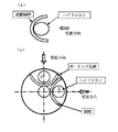
円筒型ハイドロホンは、本来指向性を有しない。
そこで、図1(a)に模式的に示すように、ハイドロホンの周方向の一部を除く周囲を
波動を遮断する遮蔽材にて囲繞して、所定方向以外の方向の感度を有しない無感度領域と
するとともに、前記ハイドロホンの前記一部の周囲を露出して、所定方向の感度を有する
有感度領域とすることにより、指向性を有しないハイドロホンに指向性を持たせることが
できる。
この指向性を有する、すなわち受波方向を制限した水中受振器用ハイドロホンは、その
受波方向が1方向に限られる。
また、指向性を有する水中受振器用ハイドロホンの有感度領域は、ボーリング孔内の水
を介して孔壁の方向性のある振動をとらえることができる。
以上のことから、請求項1に係る水中受振器用ハイドロホンは、従来の電磁型受振素子を
用いた電磁型3成分地震計のように孔壁に圧着することなく、その有感度領域をボーリン
グ孔壁に向けるだけで、孔壁に圧着した電磁型地震計と同じ性能を示す。
図1(b)は、受波方向を1方向に制限したハイドロホンを、2成分(X,Y)に組み
合わせたものを模式的に示すものである。
これは従来の電磁型受振素子を用いた電磁型3成分受振器における水平2成分とほぼ同
じ性能となる。
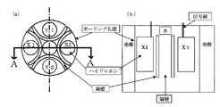
図2(a)は、ボーリング孔軸を中心にそれぞれ独立した方向に水中受振器用ハイドロ
ホンを4個設置した、請求項2に係る多点観測水中受振器を模式的に示す平面図である。
より詳しくは、感度に指向性が付与された水中受振器用ハイドロホンが、軸に沿って少
なくとも4つ設けられ、該水中受振器用ハイドロホンの有感度領域はボーリング孔壁に対
向するとともに、その周方向中央部と前記無感度領域の周方向中央部が、前記軸近傍を中
心として略等間隔に放射する少なくとも4つの偶数の放射線上に位置するように配設した
多点観測水中受振器である。
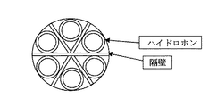
これは、図6に示すように、電磁型受振素子4個を、個別に孔壁に圧着したものと同等
の機能を有する。
図2(b)は、A−A線の断面図である。
そして。この遮蔽材である遮蔽隔壁により相互に独立した受波方向が定められ、かつ相
互に独立して信号を出力可能に配線された多点観測水中受振器は、ボーリング孔壁の周方
向4点における波動を各方向独立して観測することができる。
4個のあるいは図9に示すように6個の、少なくとも4つの水中受振器用ハイドロホンを
用いて、個々のハイドロホンの受振信号を個別に観測することにより、ボーリング孔軸中
心に対称の波動現象や非対称の波動現象などを区別できる。
例えば、図2(a)において、X1とX2で得られた波動が逆位相ならば、せん断的な
波動であり、X1とX2で得られた波動が同位相ならば、圧縮波的な波動であると推測す
ることができる。
更にはX1、X2、Y1、Y2を同時に個別に観測することにより、以下に説明するよ
うに、ボーリング孔壁の波動性状を把握することができる。
Cylindrical hydrophones are not inherently directional.
Therefore, as schematically shown in FIG. 1 (a), the periphery of the hydrophone except for a part in the circumferential direction is surrounded by a shielding material that blocks the wave, and has no sensitivity in directions other than the predetermined direction. By setting the sensitivity region and exposing the periphery of the part of the hydrophone to a sensitive region having sensitivity in a predetermined direction, the hydrophone having no directivity can have directivity. .
The hydrophone for an underwater geophone having this directivity, that is, the receiving direction is limited, has only one receiving direction.
Moreover, the sensitive area | region of the hydrophone for underwater geophones which has directivity can catch the directional vibration of a hole wall through the water in a boring hole.
From the above, the hydrophone for underwater geophone according to
FIG. 1 (b) schematically shows a combination of a hydrophone in which the receiving direction is limited to one direction in two components (X, Y).
This is almost the same performance as the horizontal two components in the electromagnetic three-component geophone using the conventional electromagnetic transducer.
FIG. 2A is a plan view schematically showing a multipoint observation underwater geophone according to
More specifically, at least four hydrophones for submersible geophones with directivity in sensitivity are provided along the axis, and the sensitive area of the hydrophone for submersible geophones is opposed to the borehole wall and its periphery. A multipoint observation underwater geophone arranged such that a central portion in the direction and a central portion in the circumferential direction of the insensitive region are positioned on at least four even-numbered radiations radiating at substantially equal intervals around the axis. .
As shown in FIG. 6, this has a function equivalent to that obtained by individually pressing four electromagnetic receiving elements on the hole wall.
FIG. 2B is a cross-sectional view taken along line AA.
And then. The multipoint observation underwater geophones that are independent of each other by the shielding partition walls, which are shielding materials, and are wired so that signals can be output independently of each other, are provided at four points in the circumferential direction of the borehole wall. Waves can be observed independently in each direction.
Using four or at least four hydrophones for underwater geophones as shown in FIG. 9 and observing the received signals of each hydrophone individually, the wave phenomenon is symmetrical about the borehole axis. And asymmetric wave phenomena.
For example, in FIG. 2A, if the wave obtained by X1 and X2 is in antiphase, it is a shear wave, and if the wave obtained by X1 and X2 is in phase, it is a compression wave. We can guess that there is.
Furthermore, by observing X1, X2, Y1, and Y2 individually at the same time, the wave properties of the borehole wall can be grasped as described below.
個々のハイドロホンから出力された信号は、後述するように、単独で、あるいは複数の
信号を加算や減算などの処理を行うことにより、地盤を伝播する地震波の振動性状を識別
し、振動性状に合致した抽出が可能となる。
ボーリング孔壁の波動を加算や減算などの処理を行うことで、振動性状を識別に供した
り、異なる振動性状を示すP波、S波に適合した処理によって波動の抽出が可能となり、
PS速度検層やVSPなどで通常用いられている電磁型受振素子から構成された3成分受
振器、あるいはハイドロホン単体に代わる受振器を構成することが可能となる。
As will be described later, the signals output from individual hydrophones are identified individually or by adding or subtracting multiple signals to identify the vibration characteristics of seismic waves propagating through the ground. Consistent extraction is possible.
By adding or subtracting the wave of the borehole wall, it is possible to identify the vibration properties, or to extract the waves by processing suitable for P and S waves showing different vibration properties.
It is possible to construct a three-component geophone configured from an electromagnetic type geophone that is normally used in PS velocity logging, VSP, or the like, or a geophone that replaces a hydrophone alone.
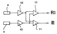
図8は、地震波の振動性状に合致した信号処理方法を模式的に示そうとするものである
。
図8(a)の2つの水中受振器用ハイドロホンX1、X2を、受振器の中心に、隔壁を
模式的に設けて対向して配置し、逆位相となるS波の場合、図8(b)に示すように波形
の差を求める。地表の孔口付近で起振した場合、S波は逆位相になるが、P波やチューブ
・ウェーブは同位相となる。このような現象を利用することにより、S波観測の妨害波と
なるチューブ・ウェーブやP波のような同位相の波をキャンセルし、的確に逆位相の波動
であるS波を抽出して観測することができる。
図8(c)の2つの水中受振器用ハイドロホンX1、X2を、受振器の中心に同じく隔
壁を模式的に設けて対向して配置し、同位相の波動を観測する場合、図8(d)に示すよ
うに波形の和を求める。地表の孔口付近で起振した場合、S波は逆位相になるが、P波や
チューブ・ウェーブは同位相となる。このため逆位相の波をキャンセルし、的確に同位相
の波動であるP波やチューブ・ウェーブを観測することができる。
ある平面の地震波の観測は、ボーリング孔壁を少なくとも4個(2対)のハイドロホン
を設けた多点観測水中受振器で観測することにより、可能となる。
また、図9に示すように、前記多点観測水中受振器のハイドロホンを3対以上とし、個
別のハイドロホンから、相互に独立して出力された信号を個別に表示すれば、地震波の受
振器に入射する状況を解明できるので、いかなる方向から発振された地震波についても適
切な観測が可能となる。
2対では、XY軸の直交する2方向であるが、3対とすれば、60°間隔で観測できるこ
とになるからである。
FIG. 8 schematically shows a signal processing method that matches the vibration characteristics of seismic waves.
In the case of the S wave having the opposite phase, the two hydrophones X1 and X2 for the underwater geophone shown in FIG. ) To find the difference in waveform. When oscillating near the hole in the ground surface, the S wave has the opposite phase, but the P wave and the tube wave have the same phase. By using such a phenomenon, the same-phase waves such as tube waves and P-waves that interfere with the S-wave observation are canceled, and the S-waves that are precisely out-of-phase waves are extracted and observed. can do.
When two hydrophones X1 and X2 for underwater geophones shown in FIG. 8C are arranged opposite to each other with a partition wall schematically provided at the center of the geophone, the same phase wave is observed. ) To obtain the sum of the waveforms. When oscillating near the hole in the ground surface, the S wave has the opposite phase, but the P wave and the tube wave have the same phase. For this reason, it is possible to cancel the wave with the opposite phase and observe the P wave and the tube wave which are exactly the same phase wave.
Observation of seismic waves on a certain plane is possible by observing the borehole wall with a multipoint observation underwater geophone equipped with at least four (two pairs) hydrophones.
In addition, as shown in FIG. 9, if the hydrophones of the multipoint observation underwater geophone have three or more pairs and the signals output independently from each hydrophone are individually displayed, the seismic wave is received. The situation of incident light on the vessel can be clarified, so it is possible to properly observe seismic waves oscillated from any direction.
This is because two pairs are in two directions orthogonal to the XY axes, but if three pairs are used, observations can be made at 60 ° intervals.
請求項1に係る発明によれば、ハイドロホンの周方向の一部を除く周囲を波動を遮断す
る遮蔽材にて囲繞して、所定方向以外の方向の感度を有しない無感度領域と、前記ハイド
ロホンの前記一部の周囲を露出して、所定方向の感度を有する有感度領域と、を具備した
感度に指向性が付与された水中受振器用ハイドロホンとしたので、ハイドロホンが従来指
向性を有していなかったため、同位相であるP波やチューブ・ウェーブの観測用に限定さ
れていたものを、波動を遮断する遮蔽材により指向性を付与することができる結果、S波
の観測用にもその用途を拡大することができる。
また、ハイドロホンを、振動の伝播を遮断するように、観測周波数領域において不動と
なる重量を有する遮蔽物で囲繞することによって、感度を有する方向からの波動を特定の
ハイドロホンに集中させ、しかもその波動をハイドロホンの全周で受感することにより、
受振感度を著しく向上することができる。
さらに、電磁型受振器の出力信号は速度振幅であるから、S波速度に比例して感度が低
下するが、この受振器はハイドロホンを用いており、このハイドロホンは加速度振幅を得
ることができる加速度型地震計であることから、S波の伝播速度が高い領域においてもそ
の感度を大きくすることができ、S波が高速度で伝播する岩盤地帯でも応用することがで
きる。
高周波数域の感度についても、感度を大きくすることができるので、高いS波速度でも
速度分解能が高くなる。
According to the first aspect of the invention, the periphery of the hydrophone except for a part in the circumferential direction is surrounded by a shielding material that blocks the wave, and the insensitive area that does not have sensitivity in a direction other than the predetermined direction; The hydrophone is a hydrophone for underwater geophones that has a sensitive area with a sensitivity in a predetermined direction by exposing the periphery of the part of the hydrophone. As a result of being able to provide directivity with a shielding material that blocks waves, what was limited to the observation of P-waves and tube waves that are in phase is used for S-wave observation. In addition, its application can be expanded.
In addition, by surrounding the hydrophone with a shield that has a weight that does not move in the observation frequency range so as to block the propagation of vibrations, the waves from the sensitive direction are concentrated on the specific hydrophone, and By sensing the vibrations all around the hydrophone,
The vibration receiving sensitivity can be remarkably improved.
Furthermore, since the output signal of the electromagnetic geophone is a velocity amplitude, the sensitivity decreases in proportion to the S wave velocity, but this geophone uses a hydrophone, and this hydrophone can obtain an acceleration amplitude. Since it is an acceleration type seismometer that can be used, the sensitivity can be increased even in a region where the propagation speed of the S wave is high, and it can also be applied to a bedrock area where the S wave propagates at a high speed.
Since the sensitivity in the high frequency range can be increased, the speed resolution is increased even at a high S wave velocity.
請求項2に係る発明によれば、ハイドロホンの周方向の一部を除く周囲を波動を遮断す
る遮蔽材にて囲繞して、所定方向以外の方向の感度を有しない無感度領域と、前記ハイド
ロホンの前記一部の周囲を露出して、所定方向の感度を有する有感度領域と、を具備した
感度に指向性が付与された水中受振器用ハイドロホンが、軸に沿って少なくとも4つ設け
られた多点観測水中受振器を、該水中受振器用ハイドロホンの有感度領域をボーリング孔
壁に対向するとともに、その周方向中央部と前記無感度領域の周方向中央部を、前記軸近
傍を中心として略等間隔に放射する偶数本の放射線上に位置するように配設したから、上
述した請求項1に係る発明の効果に加え、従来の電磁型受振素子が、ボーリング孔壁に直
接接触するように固定して、孔壁自体の振動を直接的に受振するのに対し、ハイドロホン
がボーリング孔内に充填した水を介して地盤を伝播する地震波の振動を受振することがで
きるため、電磁型受振素子を組み込んだ3方向受振器のようにボーリング孔壁に固定する
必要がなくなる。
このため、多点観測水中受振器は、単にボーリング孔に繰り入れられるケーブルに吊下
された水中受振器を目的とする深度で停止して計測を実行終了し、次の目的とする深度で
再度計測する作業を繰り返せばよいから、受振器をボーリング坑壁に固定する作業を省く
ことができるので、ボーリング孔内における地震波観測の作業性を著しく向上することが
できる。
また、感度に指向性が付与された水中受振器用ハイドロホンが、軸に沿って少なくとも
4つ設けられた多点観測水中受振器としたので、ボーリング孔の周方向について少なくと
も4点の孔壁自体の振動を受振することができる。
このため、ボーリング孔に対してあらゆる方向からの入射が想定される地震波に対し、
効果的な情報を入手することが可能となる。
また、S波とチューブ・ウェーブは、伝播速度が比較的近似していて両者を識別するこ
とが困難であったが、複数のポイントの孔壁の振動を観測して、両者の振動性状の差異か
ら、両者を明確に区分できる。またその差異を利用した処理を行うことにより、それぞれ
の振動にとっての妨害波を除去し、目的とする振動の抽出が可能となる。
さらに、従来の電磁型受振素子を用いた3成分受振器が、X成分、Y成分、Z成分の3
成分の地震計を上下方向に3段に積み重ねる関係上、受振器が縦長のものとなるが、本発
明の受振器のハイドロホンはP波を検知することが可能であるから、上下に積み重ねるこ
となく同一平面内に配置されるので、受振器のサイズをコンパクト化することができる。
さらにまた、振原を地表のみならず地中とすることも可能となり、汎用性の高い受振器
を提供することができる。
According to the second aspect of the invention, the periphery of the hydrophone except for a part in the circumferential direction is surrounded by a shielding material that blocks the wave, and the insensitive region that does not have sensitivity in a direction other than the predetermined direction; There are at least four hydrophones for underwater geophones that are sensitive to directivity and have a sensitive area that exposes the periphery of the part of the hydrophone and has sensitivity in a predetermined direction. In the multipoint observation underwater geophone, the sensitive area of the hydrophone for the underwater geophone is opposed to the borehole wall, and the circumferential center of the circumferential area and the circumferential center of the insensitive area are arranged near the axis. In addition to the effect of the invention according to
For this reason, the multipoint observation underwater geophone simply stops the underwater geophone suspended from the cable fed into the boring hole at the target depth, finishes the measurement, and measures again at the next target depth. Since the work of fixing the geophone to the borehole wall can be omitted, the workability of the seismic wave observation in the borehole can be significantly improved.
In addition, the hydrophone for underwater geophone with directivity in sensitivity is at least along the axis.
Since four multipoint observation underwater geophones are provided, it is possible to receive vibrations of at least four hole walls themselves in the circumferential direction of the borehole.
For this reason, for seismic waves that are expected to enter the borehole from all directions,
Effective information can be obtained.
In addition, the propagation speed of the S wave and tube wave was relatively close, and it was difficult to distinguish them. However, the vibration characteristics of the holes were observed by observing the vibration of the hole wall at multiple points. Therefore, the two can be clearly distinguished. Further, by performing processing using the difference, it is possible to remove the interference wave for each vibration and extract the target vibration.
Furthermore, a three-component geophone using a conventional electromagnetic type geophone is an X component, a Y component, and a Z component.
Since the seismometers of the components are stacked in three stages in the vertical direction, the geophone is vertically long. However, the hydrophone of the geophone of the present invention can detect P-waves, so Since they are arranged in the same plane, the size of the geophone can be made compact.
Furthermore, the vibration source can be not only the ground surface but also underground, and a highly versatile geophone can be provided.
請求項3に係る発明によれば、前記多点観測水中受振器を、ケーブルに所定間隔を隔て
て複数個具備して多連型多点観測水中受振器を構成したので、受振器毎に固定装置を設け
ることが不要となって受振器の構造が簡素化され、多連型受振器を製作することが容易に
なって安価に製作することができる。
また、上下方向に多数連結された各多点観測水中受振器が、一回の起振に基づいて複数
の深度における波動を同時に受振することができるため、深さ方向の多くの観測点を同一
の条件で観測することができるとともに、従来の受振器に比べ著しく計測作業を効率化す
ることができる。
According to the invention of
In addition, each multipoint observation underwater geophone connected in large numbers in the vertical direction can simultaneously receive waves at multiple depths based on a single vibration, so that many observation points in the depth direction can be the same. And the measurement work can be made more efficient than conventional geophones.
請求項4に係る発明によれば、所定の深度のボーリング孔壁の少なくとも4点以上の周
方向略等間隔の観測点において、該ボーリング孔壁の振動を液体を介して互いに独立して
受振し、受振した振動を観測点毎に電気信号に変換して出力するようにしたので、出力さ
れた観測点毎の信号を波形図に変換し、並列図示し、波形の振幅の大小や振幅の正負など
を相互に比較することにより、所定の深度の伝播振動に含まれる地震波を特定したり、地
震波の伝播状況を推測することができる。
また、出力された観測点毎の信号を、選抜した観測点あるいは全観測点の出力を加算や
減算などの演算処理をすることにより、目的とする地震波の強調、目的とする地震波の妨
害となる波動(妨害波)の影響の除去、所定の深度の伝播波動に含まれる地震波の特定、
目的とする地震波の抽出等の解析をすることができる。
According to the invention of
In addition, by adding or subtracting the output of selected observation points or the output of all observation points to the output signals for each observation point, the target seismic wave is emphasized and the target seismic wave is disturbed. Eliminating the effects of waves (jamming waves), identifying seismic waves included in propagation waves of a given depth,
Analyzes such as extraction of the target seismic wave.
図11に請求項2に係る発明の実施例を示す。図11(a)は部分的に透視する縦断面図
、図11(b)は図11(a)のA−A線断面矢視図である。
また実施例として、PS速度検層を示す。図12は左からP波とS波の波形図であり、図
13はP波とS波の走時曲線である。
以下これらの図面を参照して、本発明の多点観測水中受振器ついて詳細に説明する。
FIG. 11 shows an embodiment of the invention according to
As an example, PS velocity logging is shown. FIG. 12 is a waveform diagram of P and S waves from the left, and FIG. 13 is a travel time curve of P and S waves.
Hereinafter, the multipoint observation underwater geophone of the present invention will be described in detail with reference to these drawings.
図11を参照して、1は円柱状受振器本体で、軸方向中央部に等間隔に4つの収容部2
が形成されている。収容部が形成された円柱状受振器本体1の軸方向中央部外周は、変形
自在のスリーブ3、例えばゴムチューブにて被覆されている。この収容部2各室には、そ
れぞれ円筒型ハイドロホン4が配設されるとともに、ハイドロホン4の保護及び回路の絶
縁のためのオイルが封入されている。
なお、円柱状受振器本体1は、波動を遮断する遮蔽材を構成するものであるから、観測
周波数領域において振動の伝播を遮断するものとして、不動となる重量を有するものとし
てある。
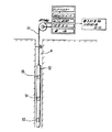
Referring to FIG. 11,
Is formed. The outer periphery of the axial center of the cylindrical geophone
Since the cylindrical geophone
前記円柱状受振器本体1の上部には、受振器本体1を地表から吊り下げるための中空ケ
ーブル6が固定されている。この中空ケーブル6内には、受振器が地震波を受けて発生し
たそれぞれの信号を地表に設置された計測装置に送信するための信号線が配線されている
。8はハイドロホンに接続された配線を、配線用端子7に接続しつつ中空収容室を密封す
るための密栓である。
中空ケーブル下端に唯1つの受振器本体1を取り付けるときは、以上の構成にて多点観
測水中受振器が完成する。
したがって、円柱状受振器本体1内には同一水平面内に少なくとも4つの円筒型圧電素
子4を配置するのみで、従来のように電磁型受振素子を円柱状受振器本体の軸方向に3段
に設ける必要がなく、加えて孔壁固定装置を設ける必要がないことから、円柱状受振器本
体1自体をコンパクト化することができる。
A
When only one geophone
Therefore, in the cylindrical geophone
一方、受振器本体中央部にも、中空ケーブル6を挿通するための挿通用孔9を形成して
ある。
中空ケーブル6に複数の多点観測水中受振器を取り付けるときは、図11(a)に示した
挿通用孔9を介して中空ケーブル6を下方に向けて延長し、この延長ケーブル下端に受振
器を取り付ければよい。
このようにして、多連型多点観測水中受振器を構成するものである。
On the other hand, an insertion hole 9 for inserting the
When a plurality of multipoint observation underwater geophones are attached to the
In this way, a multiple-type multipoint observation underwater geophone is constructed.
ハイドロホンはインピーダンスが高く、また個体差もある。このため各ハイドロホンの
感度、周波数特性を等しくしなければ和や差を求めたとき、正しい孔壁の振動を求めるこ
とはできない。
そこでハイドロホン4を図14に示すプリアンプ10に接続し、感度、周波数特性を合
わせてから出力するとともに、次段の差動アンプ11で和または差を求める回路を用いる
のが好ましい。
本実施例では、孔軸を中心に孔壁の複数のポイントにおける波動を個別に独立して観測
することにより、3成分受振器の目的とするS波とP波を、妨害波であるチューブ・ウェ
ーブの影響を受けることなく、適切に観測できることが重要な特徴である。
本受振器は、孔壁全周の波動を同時に観測することから、ボーリング孔軸中心に位置す
ることが望ましく、使用に際しては、セントライザー(中心位置保持装置)を用いること
が望ましい。
また、水中受振器用ハイドロホンの組込み数を、たとえば6や8に増やすことにより、
ボーリング孔壁の波動状態を詳細に解析することができるようになる。その際、図11に
示された多点観測水中受振器を相互に位相をずらして上下2段に設けるとよい。
Hydrophones have high impedance and individual differences. For this reason, when the sum and the difference are obtained unless the sensitivity and frequency characteristics of the hydrophones are made equal, correct vibration of the hole wall cannot be obtained.
Therefore, it is preferable to use a circuit in which the
In this embodiment, by independently and independently observing the waves at a plurality of points on the hole wall around the hole axis, the S wave and the P wave intended for the three-component geophone are converted into a tube wave that is an interference wave. An important feature is the ability to observe properly without being affected by waves.
The geophone is preferably located at the center of the borehole axis because it simultaneously observes the wave around the entire circumference of the hole wall. In use, it is desirable to use a centrizer (center position holding device).
Also, by increasing the number of hydrophones for underwater geophones to 6 or 8, for example,
The wave state of the borehole wall can be analyzed in detail. At that time, the multipoint observation underwater geophone shown in FIG. 11 may be provided in two upper and lower stages with mutually shifted phases.
多点観測水中受振器は、この実施例では、円筒型圧電素子を、ゴムスリーブで覆い且つ
オイルで充填した、独立して区画割した収容部に格納して、一体型受振器として構成して
いるが、個別に円筒型圧電素子をモールドしたハイドロホンを、図9に示すような、放射
状に延びる振動を遮断する遮蔽隔壁にて区画割した空間に格納することによっても可能で
ある。
(S波の観測)
In this embodiment, the multipoint observation underwater geophone is configured as an integrated geophone by storing a cylindrical piezoelectric element in an independently partitioned housing section covered with a rubber sleeve and filled with oil. However, it is also possible to store a hydrophone in which a cylindrical piezoelectric element is individually molded in a space divided by a shielding partition wall that blocks vibration extending radially as shown in FIG.
(S-wave observation)
S波の振源を地表に置いて、ボーリング孔内に多点観測水中受振器を目的とする深度ま
で挿入し、図3に示すようにS波の振源を水平1方向から打撃し受振器にて受振する。そ
うすると、対向して配置された少なくとも2対のハイドロホン4(a)、4(b)が、地
表に設置した計測装置に配線を介して電気信号を送信する。
Place the S wave source on the ground, insert the multipoint observation underwater geophone into the borehole to the desired depth, and strike the S wave source from one horizontal direction as shown in FIG. Receive vibration at. Then, at least two pairs of hydrophones 4 (a) and 4 (b) arranged to face each other transmit an electrical signal to the measuring device installed on the ground surface via the wiring.
次いで、受振器を同じ深度に維持したまま、S波の振源を水平の逆方向から打撃し逆位
相の地震波を受振器にて受振する。そして同じく、対向して配置された少なくとも2対の
ハイドロホン4(a)、4(b)が、地表に設置した計測装置に配線を介して電気信号を
送信する。
(P波の観測)
Next, while maintaining the geophone at the same depth, the S wave source is struck from the horizontal reverse direction, and the seismic wave having the opposite phase is received by the geophone. Similarly, at least two pairs of hydrophones 4 (a) and 4 (b) arranged opposite to each other transmit an electrical signal to the measuring device installed on the ground surface via wiring.
(P-wave observation)
さらに、受振器を同じ深度に維持したまま、P波の振源を鉛直方向に打撃し地震波を受
振器にて受振する。そして、対向して配置された少なくとも2対のハイドロホン4(a)
、4(b)が、地表に設置した計測装置に配線を介して電気信号を送信する。
Further, while maintaining the geophone at the same depth, the P wave source is hit in the vertical direction and the seismic wave is received by the geophone. And at least two pairs of hydrophones 4 (a) arranged opposite to each other
4 (b) transmits an electrical signal via a wiring to a measuring device installed on the ground surface.
所定の深度におけるS波及びP波の観測が終了した時点で、多点観測水中受振器の深度
を1段階下げ、再び上記の観測を実行し、この作業を繰り返し所定の深度に達するまで実
行する。
この作業の繰り返しにより必要とするデータを取得することができる。
(S波、P波速度の解析)
When the observation of S waves and P waves at a predetermined depth is completed, the depth of the multipoint observation underwater geophone is lowered by one step, the above observation is performed again, and this operation is repeated until the predetermined depth is reached. .
Necessary data can be acquired by repeating this operation.
(S-wave and P-wave velocity analysis)
S波が図8(a)に示すように、左方向のせん断波として入射した場合、ハイドロホン
X1は圧縮の、X2は引張の振動を受振するので、図8(b)に示すように逆位相の信号
を発生する。したがってS波については、対向するハイドロホン4の信号の差をとり、同
位相のノイズをキャンセルして振幅が大きい増幅されたデータをS波として抽出する。
そして、1方向と逆方向の波形図を作成し、波形図の初動点から走時曲線を得て、観測
地点における地震波伝播速度を割り出し、PS速度検層とする。
When the S wave is incident as a shear wave in the left direction as shown in FIG. 8A, the hydrophone X1 receives the compression vibration and the X2 receives the tensile vibration, so that the reverse as shown in FIG. 8B. Generate a phase signal. Therefore, for the S wave, the difference between the signals of the
Then, a waveform diagram in the direction opposite to the one direction is created, a travel time curve is obtained from the initial movement point of the waveform diagram, the seismic wave propagation velocity at the observation point is determined, and PS velocity logging is performed.
一方、P波が図8(c)に示すように左右両方向から圧縮波として入射した場合、ハイ
ドロホンX1、ハイドロホンX2の双方が圧縮の振動を受振する。
このため、同図(b)に示すように同位相の信号を発生する。
なおP波については上述のS波とは若干異なり、振源の位置などに応じて以下の種々の
解析手法を採り得る。
(1)最も適切と考えられる個別のハイドロホンの信号
(2)全てのハイドロホンの信号の和
(3)最も大きい対向するハイドロホンの和
On the other hand, when the P wave is incident as a compression wave from both the left and right directions as shown in FIG. 8C, both the hydrophone X1 and the hydrophone X2 receive the compression vibration.
For this reason, signals having the same phase are generated as shown in FIG.
The P wave is slightly different from the S wave described above, and the following various analysis methods can be adopted depending on the position of the vibration source.
(1) Individual hydrophone signals considered most appropriate (2) Sum of all hydrophone signals (3) Sum of largest opposing hydrophones
1 多点観測水中受振器本体
2 収容部
3 変形自在のスリーブ
4 水中受振器用ハイドロホン
5 遮蔽鯛(遮断物、遮蔽隔壁)
6 中空ケーブル
7 配線用端子
8 密栓
9 挿通用孔
10 プリアンプ
11 プリアンプ(和、差)
51 ケーブル
52 ゾンデ
53 発振器
54 第1の受振器
55 第2の受振器
1 Multi-point observation
6
51
Claims (4)
方向以外の方向の波動に対して感度を有しない無感度領域と、
前記ハイドロホンの前記一部の周囲が露出されて、所定方向の波動に対して感度を有す
る有感度領域と、
を具備してなる波動に対する感度に指向性が付与された水中受振器用ハイドロホン。 A non-sensitivity region that is surrounded by a shielding material that blocks a wave except for a part of the circumferential direction of the hydrophone and has no sensitivity to a wave in a direction other than a predetermined direction;
A sensitive region in which the periphery of the part of the hydrophone is exposed and has sensitivity to a wave in a predetermined direction;
A hydrophone for an underwater geophone with directivity applied to sensitivity to waves.
方向以外の方向の波動に対して感度を有しない無感度領域と、
前記ハイドロホンの前記一部の周囲が露出されて、所定方向の波動に対して感度を有す
る有感度領域と、
を具備してなる波動に対して感度に指向性が付与された水中受振器用ハイドロホンが、
軸に沿って少なくとも4つ設けられた多点観測水中受振器であって、
該水中受振器用ハイドロホンの有感度領域はボーリング孔壁に対向するとともに、その
周方向中央部と前記無感度領域の周方向中央部が、前記軸近傍を中心として略等間隔に放
射する少なくとも4つの偶数の放射線上に位置するように配設されている多点観測水中受
振器。 A non-sensitivity region that is surrounded by a shielding material that blocks a wave except for a part of the circumferential direction of the hydrophone and has no sensitivity to a wave in a direction other than a predetermined direction;
A sensitive region in which the periphery of the part of the hydrophone is exposed and has sensitivity to a wave in a predetermined direction;
A hydrophone for underwater geophones with directivity in sensitivity to waves
A multipoint observation underwater geophone provided with at least four along an axis,
The sensitive region of the hydrophone for underwater geophone is opposed to the borehole wall, and the circumferential central portion thereof and the circumferential central portion of the insensitive region radiate at substantially equal intervals around the axis. A multipoint observation underwater geophone that is arranged to be located on two even numbers of radiation.
とする請求項2に記載された多連型多点観測水中受振器。 3. The multiple-point multi-point observation underwater geophone according to claim 2, wherein a plurality of multi-point observation underwater geophones are provided on the cable at a predetermined interval.
いて、該ボーリング孔壁の振動を液体を介して互いに独立して受振し、受振した振動を観
測点毎に電気信号に変換して出力し、出力された観測点毎の信号を、波形図に変換して比
較し、または選抜した観測点あるいは全観測点の出力を加算や減算等の演算処理をするこ
とにより、地震波を特定し、地震波の伝播状況を推測し、または目的とする地震波を抽出
して、地盤の所定の振動を解析する方法。 At at least four even points of the borehole wall of a predetermined depth at the observation points at substantially equal intervals in the circumferential direction, vibrations of the borehole wall are received independently from each other through the liquid, and the received vibrations are received for each observation point. Convert to electrical signal and output, convert the output signal for each observation point to waveform diagram and compare, or perform processing such as addition or subtraction for the output of selected observation points or all observation points The method of analyzing the predetermined vibration of the ground by identifying the seismic wave, estimating the propagation situation of the seismic wave, or extracting the target seismic wave.
Priority Applications (1)
| Application Number | Priority Date | Filing Date | Title |
|---|---|---|---|
| JP2004106855A JP2005291903A (en) | 2004-03-31 | 2004-03-31 | Hydrophone for underwater geophone, and multipoint observation underwater geophone |
Applications Claiming Priority (1)
| Application Number | Priority Date | Filing Date | Title |
|---|---|---|---|
| JP2004106855A JP2005291903A (en) | 2004-03-31 | 2004-03-31 | Hydrophone for underwater geophone, and multipoint observation underwater geophone |
Publications (1)
| Publication Number | Publication Date |
|---|---|
| JP2005291903A true JP2005291903A (en) | 2005-10-20 |
Family
ID=35324992
Family Applications (1)
| Application Number | Title | Priority Date | Filing Date |
|---|---|---|---|
| JP2004106855A Pending JP2005291903A (en) | 2004-03-31 | 2004-03-31 | Hydrophone for underwater geophone, and multipoint observation underwater geophone |
Country Status (1)
| Country | Link |
|---|---|
| JP (1) | JP2005291903A (en) |
Cited By (8)
| Publication number | Priority date | Publication date | Assignee | Title |
|---|---|---|---|---|
| KR100838690B1 (en) | 2006-12-04 | 2008-06-16 | (주) 소암컨설턴트 | E-beam energy radial modulation |
| JP2009025104A (en) * | 2007-07-18 | 2009-02-05 | Tokyo Electric Power Co Inc:The | Reflection method |
| JP2009175122A (en) * | 2007-12-28 | 2009-08-06 | Kajima Corp | Method of oscillating elastic wave transmitted underground, and ground survey method |
| JP2010031576A (en) * | 2008-07-30 | 2010-02-12 | Kajima Corp | Device and method for detecting reaching of tip of cast-in-place pile at supporting layer |
| JP2010071672A (en) * | 2008-09-16 | 2010-04-02 | Shimizu Corp | Device for measuring hydraulic pressure of groundwater |
| JP2016136121A (en) * | 2015-01-23 | 2016-07-28 | 特許機器株式会社 | Ground vibration measuring device |
| JP2017067562A (en) * | 2015-09-29 | 2017-04-06 | 株式会社Ihi | Water area underground survey system and water area underground survey method |
| CN115248076A (en) * | 2022-06-28 | 2022-10-28 | 中国船舶重工集团公司第七一五研究所 | Dual-transmitting transducer inverse sound path method for measuring the complex sensitivity phase of hydrophones |
-
2004
- 2004-03-31 JP JP2004106855A patent/JP2005291903A/en active Pending
Cited By (8)
| Publication number | Priority date | Publication date | Assignee | Title |
|---|---|---|---|---|
| KR100838690B1 (en) | 2006-12-04 | 2008-06-16 | (주) 소암컨설턴트 | E-beam energy radial modulation |
| JP2009025104A (en) * | 2007-07-18 | 2009-02-05 | Tokyo Electric Power Co Inc:The | Reflection method |
| JP2009175122A (en) * | 2007-12-28 | 2009-08-06 | Kajima Corp | Method of oscillating elastic wave transmitted underground, and ground survey method |
| JP2010031576A (en) * | 2008-07-30 | 2010-02-12 | Kajima Corp | Device and method for detecting reaching of tip of cast-in-place pile at supporting layer |
| JP2010071672A (en) * | 2008-09-16 | 2010-04-02 | Shimizu Corp | Device for measuring hydraulic pressure of groundwater |
| JP2016136121A (en) * | 2015-01-23 | 2016-07-28 | 特許機器株式会社 | Ground vibration measuring device |
| JP2017067562A (en) * | 2015-09-29 | 2017-04-06 | 株式会社Ihi | Water area underground survey system and water area underground survey method |
| CN115248076A (en) * | 2022-06-28 | 2022-10-28 | 中国船舶重工集团公司第七一五研究所 | Dual-transmitting transducer inverse sound path method for measuring the complex sensitivity phase of hydrophones |
Similar Documents
| Publication | Publication Date | Title |
|---|---|---|
| US4832148A (en) | Method and system for measuring azimuthal anisotropy effects using acoustic multipole transducers | |
| US8902700B2 (en) | Borehole seismic acquisition system | |
| US7257489B2 (en) | Quadrupole acoustic shear wave logging while drilling | |
| CA2579982C (en) | Anisotropy measurement while drilling | |
| US5753812A (en) | Transducer for sonic logging-while-drilling | |
| CN101910870B (en) | Seismic Sensor Device | |
| USH1561H (en) | Method and apparatus for detection of seismic and electromagnetic waves | |
| US20100157737A1 (en) | Microhydraulic fracturing with downhole acoustic measurement | |
| USH1524H (en) | Method for using electromagnetic grounded antennas as directional geophones | |
| IE872764L (en) | Multipole acoustic logging | |
| CA2367784C (en) | Acoustic logging apparatus and method | |
| US7424928B2 (en) | Apparatus, system and method for flexibly coupling sensors to a downhole tool | |
| CN111708080A (en) | Four-component fiber optic seismic data acquisition device and data acquisition method in array well | |
| US7252174B2 (en) | Downhole seismic-sonic receiver | |
| US9897710B2 (en) | Borehole seismic acquisition tools, systems and methods | |
| JP2005291903A (en) | Hydrophone for underwater geophone, and multipoint observation underwater geophone | |
| Koedel et al. | Evaluating distributed acoustic sensing for crosswell seismic surveys with helical and linear fibers using conventional P-, SH-, and SV-wave sources | |
| Schmitt et al. | Shear-wave logging using multipole sources | |
| US20160320511A1 (en) | A borehole seismic tool and method of seismic surveying | |
| US20220179112A1 (en) | Detecting and monitoring formation features with an optical fiber | |
| US5226017A (en) | Method and apparatus for acquiring borehole seismic data in two opposite directions | |
| RU2823220C1 (en) | Detection and observation of distinctive features of deposit formation using optical fiber | |
| JP2000186319A (en) | Ground investigation method | |
| CA1295725C (en) | Method and system for measuring azimuthal anisotropy effects using acoustic multipole transducers | |
| Zhao et al. | Processing acoustic vector array logging data to image near-borehole geologic structures |
Legal Events
| Date | Code | Title | Description |
|---|---|---|---|
| A621 | Written request for application examination |
Free format text: JAPANESE INTERMEDIATE CODE: A621 Effective date: 20070309 |
|
| A977 | Report on retrieval |
Free format text: JAPANESE INTERMEDIATE CODE: A971007 Effective date: 20080926 |
|
| A131 | Notification of reasons for refusal |
Free format text: JAPANESE INTERMEDIATE CODE: A131 Effective date: 20081031 |
|
| A02 | Decision of refusal |
Free format text: JAPANESE INTERMEDIATE CODE: A02 Effective date: 20090303 |