JP2005291713A - Torque sensor - Google Patents
Torque sensor Download PDFInfo
- Publication number
- JP2005291713A JP2005291713A JP2004102512A JP2004102512A JP2005291713A JP 2005291713 A JP2005291713 A JP 2005291713A JP 2004102512 A JP2004102512 A JP 2004102512A JP 2004102512 A JP2004102512 A JP 2004102512A JP 2005291713 A JP2005291713 A JP 2005291713A
- Authority
- JP
- Japan
- Prior art keywords
- circuit board
- torque sensor
- steering
- shaft
- insertion holes
- Prior art date
- Legal status (The legal status is an assumption and is not a legal conclusion. Google has not performed a legal analysis and makes no representation as to the accuracy of the status listed.)
- Pending
Links
- 238000003780 insertion Methods 0.000 claims abstract description 61
- 230000037431 insertion Effects 0.000 claims abstract description 61
- 238000001514 detection method Methods 0.000 claims abstract description 36
- 230000002093 peripheral effect Effects 0.000 description 4
- 239000000758 substrate Substances 0.000 description 4
- 230000008878 coupling Effects 0.000 description 3
- 238000010168 coupling process Methods 0.000 description 3
- 238000005859 coupling reaction Methods 0.000 description 3
- 238000010586 diagram Methods 0.000 description 2
- 239000000696 magnetic material Substances 0.000 description 2
- 230000000149 penetrating effect Effects 0.000 description 2
- 238000005476 soldering Methods 0.000 description 2
- 238000004519 manufacturing process Methods 0.000 description 1
- 125000006850 spacer group Chemical group 0.000 description 1
Images

Landscapes
- Power Steering Mechanism (AREA)
Abstract
Description
本発明は、主として自動車のパワーステアリング装置において、ハンドル等の操舵部材に加えられる操舵トルクを検出するトルクセンサに関する。 The present invention relates to a torque sensor that detects a steering torque applied to a steering member such as a steering wheel in a power steering apparatus for an automobile.
自動車のパワーステアリング装置、例えば電動パワーステアリング装置は、ハンドルに加えられた操舵トルクをトルクセンサにより検出し、その検出トルクに応じて、ステアリングシャフト(操舵軸)もしくはステアリング機構(操舵機構)に設けられている電動モータを駆動して、ステアリング機構を駆動する力を補助する構造となっている。 A power steering device of an automobile, for example, an electric power steering device, detects a steering torque applied to a steering wheel by a torque sensor, and is provided on a steering shaft (steering shaft) or a steering mechanism (steering mechanism) according to the detected torque. The electric motor is driven to assist the driving force of the steering mechanism.
上記の電動パワーステアリング装置において、ステアリングシャフトの中途部は、ハンドル側の入力軸と、ステアリング機構側の出力軸とに分割されて、これら入力軸と出力軸とは、軸方向に互いに対向する状態で、ねじり変形可能なトーションバーを介して同軸に連結されている。トルクセンサは、入力軸と出力軸との軸方向対向部の外周に設けられており、内周に検出用コイルおよび温度補償用コイルを有する環状の検出部と、この検出部の外周の一部に取付けられる回路基板とを備え、トーションバーのねじれに伴い入力軸と出力軸との間に生じる相対角変化を、検出用コイルでのインピーダンスの変化として検出するようになっている。 In the electric power steering apparatus described above, the middle portion of the steering shaft is divided into an input shaft on the steering wheel side and an output shaft on the steering mechanism side, and the input shaft and the output shaft face each other in the axial direction. Thus, they are coaxially connected via a torsion bar that can be torsionally deformed. The torque sensor is provided on the outer periphery of the axially facing portion between the input shaft and the output shaft, and an annular detection unit having a detection coil and a temperature compensation coil on the inner periphery, and a part of the outer periphery of the detection unit And a relative angle change generated between the input shaft and the output shaft as the torsion bar is twisted is detected as a change in impedance in the detection coil.
トルクセンサの検出部は、入力軸や出力軸を回転可能に支持するセンサハウジングの内部に収容されている。トルクセンサの回路基板は、センサハウジングの外周の一部に一体に形成された基板ボックス内に配置されて、その面上に形成された挿通孔に、検出部から突出する接続端子を挿通し半田付けすることで、検出部に取付けられている(例えば、特許文献1参照)。
パワーステアリング装置では、この装置が実装される自動車のタイプ毎にトルクセンサの検出部の配置位置が変わり、それに応じて、この検出部を収容するセンサハウジングの形状が変化し、センサハウジングでの基板ボックスの形状や形成位置も変化する。トルクセンサについては、検出部に対する回路基板の取付け位置が異なってくる。 In the power steering device, the arrangement position of the detection portion of the torque sensor changes for each type of automobile on which the device is mounted, and the shape of the sensor housing that accommodates this detection portion changes accordingly, and the substrate in the sensor housing The shape and position of the box will also change. As for the torque sensor, the mounting position of the circuit board with respect to the detection unit is different.
上記の変化に応じて、回路基板では、異なった位置に挿通孔を形成する等、レイアウトを変更する必要が生じる。しかし、車種毎に、レイアウトの異なる種々の回路基板を用意するとなると、コストがかさみ、製造上の負担が大きくなるばかりか、トルクセンサやその装着部分の設計変更が容易に行えなくなる、という問題がある。 In accordance with the above change, the circuit board needs to be changed in layout, for example, through holes are formed at different positions. However, when various circuit boards with different layouts are prepared for each vehicle model, there is a problem that not only the cost is increased and the manufacturing burden is increased, but also the design of the torque sensor and its mounting portion cannot be easily changed. is there.
本発明によるトルクセンサは、環状の検出部と、この検出部の外周の一部から突出する接続端子に取付けられる回路基板とを備えたトルクセンサにおいて、回路基板には、接続端子の本数より多い個数で、接続端子が回路基板上の複数の異なる位置でそれぞれ挿通可能な挿通孔が形成されていることを特徴とするものである。 The torque sensor according to the present invention is a torque sensor including an annular detection portion and a circuit board attached to a connection terminal protruding from a part of the outer periphery of the detection portion. The circuit board has more than the number of connection terminals. The number of insertion holes through which the connection terminals can be inserted at a plurality of different positions on the circuit board is formed.
上記構成において、接続端子が4本である場合、挿通孔は、少なくとも接続端子の本数(4本)より2個多い6個あればよい。 In the above configuration, when there are four connection terminals, the number of insertion holes may be at least six, which is two more than the number of connection terminals (four).
上記構成のトルクセンサでは、回路基板にある挿通孔のうちから、接続端子と同数の一組の挿通孔を選択して、これらの挿通孔群に接続端子を挿通することで、回路基板上のそれまでの取付け位置と隣り合った位置や、一部重複する位置等、異なった位置で回路基板を検出部に取付けることができ、回路基板と検出部とは、相対位置を変えて組み合わせることができる。 In the torque sensor having the above configuration, the same number of insertion holes as the connection terminals are selected from the insertion holes in the circuit board, and the connection terminals are inserted into these insertion hole groups, so that The circuit board can be attached to the detector at a different position, such as a position adjacent to the previous mounting position or a partially overlapping position. The circuit board and the detector can be combined at different relative positions. it can.
そのため、センサハウジングの形状変更等により、検出部に対する回路基板の取付け位置を変える必要が生じても、回路基板を変えずに対応でき、挿通孔の位置等、レイアウトの異なる回路基板を新たに用意する必要がない。 Therefore, even if it is necessary to change the mounting position of the circuit board with respect to the detector due to changes in the shape of the sensor housing, etc., it can be handled without changing the circuit board, and a new circuit board with a different layout such as the position of the insertion hole is prepared. There is no need to do.
本発明によれば、検出部への回路基板の取付け位置を変える必要が生じても、回路基板を変えずに対応でき、トルクセンサやその装着部分の設計変更の自由度が増すばかりか、製造コストの削減に役立つ。 According to the present invention, even if it is necessary to change the mounting position of the circuit board to the detection unit, it can be handled without changing the circuit board, and the degree of freedom in changing the design of the torque sensor and its mounting portion is increased. Helps reduce costs.
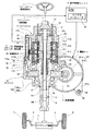
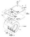
図面を参照して、本発明による最良の形態に係るトルクセンサを説明すると、図1は、同トルクセンサを含む電動パワーステアリング装置を、関連する車両構成と共に示す概略構成図で、主要部は軸方向に沿って断面して示している。図2は、図1の装置に含まれるトルクセンサの分解斜視図、図3は、図2のトルクセンサの一部である回路基板の部分平面図である。 A torque sensor according to the best mode of the present invention will be described with reference to the drawings. FIG. 1 is a schematic configuration diagram showing an electric power steering apparatus including the torque sensor together with a related vehicle configuration. A cross section is shown along the direction. 2 is an exploded perspective view of a torque sensor included in the apparatus of FIG. 1, and FIG. 3 is a partial plan view of a circuit board that is a part of the torque sensor of FIG.
この電動パワーステアリング装置は、コラムアシストタイプであって、操舵部材としてのステアリングホイール(ハンドル)1に一端が連結されたステアリングシャフト(操舵軸)2と、ステアリングホイール1の操作によってステアリングシャフト2に加えられる操舵トルクを検出するトルクセンサ3と、駆動により操舵補助トルクを発生させる電動モータ4と、この電動モータ4の回転を減速してステアリングシャフト2に伝達する減速機構5と、トルクセンサ3や車速センサ、エンジン回転センサ等のセンサの出力信号に基づいて電動モータ4の駆動を制御する電子制御ユニット(ECU)6とを備えている。
This electric power steering apparatus is of a column assist type, and includes a steering shaft (steering shaft) 2 having one end connected to a steering wheel (steering wheel) 1 as a steering member, and an operation of the steering wheel 1 in addition to the
ステアリングシャフト2の他端は、図示省略した下部軸を介して、ステアリング機構(舵取機構)7に連結されている。ステアリング機構7は、例えばラックアンドピニオン式のもので、図示しないが、操舵操作により回転するピニオンと、このピニオンに噛み合うラック軸とを有し、ピニオンはステアリングシャフト2の他端に連結され、ラック軸の両端は、タイロッドおよびナックルアーム等からなる連結部材8を介して操向用の車輪9に連結されている。
The other end of the
ECU6は、マイクロコンピュータ61を中心に構成されており、特に図示しないが、センサ用インタフェースやモータ駆動回路等の周辺回路を含んでいる。ECU6のマイクロコンピュータ61は、トルクセンサ3等のセンサからの出力信号に基づいて、操舵補助に適したトルクを発生するのに必要な電動モータ4の駆動量を演算し、その駆動量に対応する制御信号により電動モータ4を駆動する。
The ECU 6 is configured around a
以下、電動パワーステアリング装置の主要部の説明では、電動パワーステアリング装置の車両への実装状態に即して、ステアリングホイール1に近い側を上側もしくは上端、ステアリング機構7に近い側を下側もしくは下端という。 Hereinafter, in the description of the main part of the electric power steering device, the side close to the steering wheel 1 is the upper side or the upper end, and the side closer to the steering mechanism 7 is the lower side or the lower end according to the mounting state of the electric power steering device on the vehicle. That's it.
ステアリングシャフト2の中途部は、ステアリングホイール1側から順に、上部軸10と、筒状の入力軸11と、トーションバー12と、筒状の出力軸13とから構成されている。
The middle part of the
ステアリングシャフト2の上部軸10は、ステアリングホイール1と一体に回転しうる状態でステアリングコラム14内に挿通されている。入力軸11は、その筒状内部に挿入したトーションバー12とともに、径方向に貫通するピン15により上部軸10の下端部に連結されている。トーションバー12は、その中間部12cに長尺で細径のねじり領域を有するもので、大径円柱形状をなす上端部12aが前記したように上部軸10に連結されるとともに、同じく大径円柱形状をなす下端部12bが出力軸13の筒状内部に挿入されて、径方向に貫通するピン16により出力軸13に連結されている。このトーションバー12の外周で、入力軸11はトーションバー12の下端側へ、また出力軸13はトーションバー12の上端側へそれぞれ延出しており、それらの延出部は、トーションバー12の中間部12cの外周で互いに軸方向に対向するとともに、径方向内外に入れ子状に外嵌内挿されている。
The
トルクセンサ3はセンサハウジング17に収容され、また、減速機構5はギヤハウジング18に収容されている。センサハウジング17とギヤハウジング18とは、ステアリングシャフト2の中途部の周りに軸方向上下に配置されて互いに結合され、その結合状態でステアリングコラム14の下部を構成している。これらセンサハウジング17およびギヤハウジング18のさらに詳しい構造、形状については、その内部に収容するトルクセンサ3や、減速機構5の構成に関連付けて後述する。
The
トルクセンサ3は、入力軸11と出力軸13との軸方向対向部の外周に配置されている。このトルクセンサ3は、図2にも示すように、センサハウジング17の内径側に設けられる環状の検出部31と、この検出部31の外周の一部に取付けられる回路基板32とを備えている。
The
検出部31は、磁性材料からなるケース313,314をそれぞれに有する検出用コイル311と温度補償用コイル312とをカバー315で被覆したものである。検出用コイル311および温度補償用コイル312は、それぞれ内周面部が内径側に露出する状態で対応するケース313,314に収容され、両ケース313,314の間に設けたスペーサ316を介して軸方向に並列配置されている。これら両コイル311,312は、通電により、各コイル311,312のケース313,314と、両コイル311,312の内周で入力軸11および出力軸13の外周面に取付けられた磁性体製のリング19,20,21との間に磁気回路を形成する。検出用コイル311の周りに形成される磁気回路の磁気抵抗は、トーションバー12のねじれに伴い、入力軸11に対して出力軸13が回転方向に位置ずれすることで変化し、この変化に応じて検出用コイル311のインピーダンスを変化させる。トルクセンサ3は、トーションバー12のねじれを、検出用コイル311でのインピーダンスの変化として検出するようになっている。
The detection unit 31 includes a
検出部31のカバー315は、ほぼ円筒状で、各コイル311,312を収容する2つのケース313,314の外周面と軸方向外端面とを覆っている。このカバー315の軸方向中間の外周の一部には、径方向外方に突出する端子保持部315aが一体に設けられており、この端子保持部315aから、4本一組の接続端子22a,22b,22c,22d(22と総称)が突出している。これら接続端子22は、各コイル311,312に接続されたもので、端子保持部315aの頂部上で縦横方向、図示例では、軸方向Xおよび軸直交方向Yにそれぞれ2列で、かつ軸方向Xの相互間隔sと軸直交方向Yの相互間隔tとを互いに同一(s=t)にして配列されている。
The
回路基板32は、検出部31の各コイル311,312へのコイル電流の給電のための電源回路や、各コイル311,312の出力取り出しのための処理回路を搭載するもので、図面には回路基板32のみを図示している。この回路基板32の一部には、接続端子22の取付け領域32Aが設定され、この取付け領域32A内に、接続端子22を挿通するための挿通孔23a,23b,23c,23d,24a,24b,24c,24dが形成されている。これら挿通孔23a〜23d,24a〜24dは、一組の接続端子22の本数(4本)よりも4個多い個数(8個)ある。
The
8個の挿通孔23a〜23d,24a〜24dは、軸方向Xに沿って2列で、軸直交方向Yに沿って4列に配列されており、図3に明示するように、これら8個の挿通孔23a〜23d,24a〜24dのうち、軸方向Xの一方側(図2および図3で左側)の4個23a〜23dが、一組の接続端子22に対応する第1の挿通孔群23を形成しており、軸方向Xの他方側(右側)の4個の挿通孔24a〜24dが、一組の接続端子22に対応する第2の挿通孔群24を形成している。
The eight
各挿通孔群23,24において、挿通孔23a〜23d,24a〜24dは、一組の接続端子22と同様に、軸方向Xにも軸直交方向Yにも、接続端子22の相互間隔s,tと同一の相互間隔u,vで配列されている(u,v=s,t)。第1の挿通孔群23と第2の挿通孔群24との間には、各挿通孔群23,24での軸方向Xの挿通孔間の相互間隔uと同一の相互間隔w(w=u)が設定されている。また、第1の挿通孔群23と第2の挿通孔群24との間では、挿通孔23aと挿通孔24aとのように、同一の接続端子22a〜22dに対応する挿通孔どうしが、それぞれジャンパパターン25a,25b,25c,25d(25と総称)により接続されている。
In each of the
8個の挿通孔23a〜23d,24a〜24dのうち、いずれか4個の挿通孔、例えば、第1の挿通孔群23に属する挿通孔23a〜23dには接続端子22a〜22dが挿通され、半田付けにより相互に固定されるともに、接続端子22a〜22dが回路基板32の裏面もしくは表面に形成された導電パターン(図示省略)に電気的に接続される。回路基板32の表面側には接続部26が設けられ、この接続部26から、電源供給や信号取り出しのためのハーネス27が導出されている。
Of the eight
図1に戻って、トルクセンサを収容するセンサハウジング17は、上端部がステアリングコラム14に結合されて、ステアリングコラム14に近い位置で針状ころ軸受28により入力軸11を回転可能に支持し、下端側では、その内周に設けた玉軸受29により出力軸13を回転可能に支持している。
Returning to FIG. 1, the sensor housing 17 that accommodates the torque sensor has an upper end coupled to the
このセンサハウジング17は、内部にトルクセンサ3の検出部31を収容する検出部収容部171と、内部に回路基板32を収容する基板ボックス172とを有している。検出部収容部171の内部には、検出部31が軸方向下側から挿入されて、止め輪34により挿入した状態に固定されている。符号173は、センサハウジング17に軸方向に形成された挿入路で、この挿入路173を通じて、トルクセンサ3の端子保持部315aや接続端子22が軸方向内側に入り込むようになっている。
The sensor housing 17 includes a detection
基板ボックス172は、センサハウジング17の外周部の一部に、径方向外方に開放された形に形成されている。この基板ボックス172の内部に設けられた段部172aに、回路基板32が接続端子22に取付けられた状態で、ねじ35により固定されている。回路基板32の外側は、基板ボックス172の開放部にねじ36により止着されるカバー板37により被覆されている。
The
減速機構5は、駆動ギヤとしてのウォーム軸51と、従動ギヤとしてのウォームホイール52とを備え、これらウォーム軸51およびウォームホイール52は、ギヤハウジング18の内部に収容されている。ウォームホイール52は、センサハウジング17側の玉軸受29とギヤハウジング18の下端側の玉軸受38との間で、出力軸13に同軸に固着されている。
The reduction mechanism 5 includes a
減速機構5を収容するギヤハウジング18は、センサハウジング17の下部に結合されて、その下端側の内周に設けた玉軸受38により出力軸13を回転可能に支持しており、ウォームホイール収容部(従動ギヤ収容部)182と、ウォーム軸収容部(駆動ギヤ収容部)181とからなる。
The
ギヤハウジング18のウォームホイール収容部182は、両端開放の段付き円筒形状で、内部にウォームホイール52を収容する大径円筒部182aと、玉軸受38を介して出力軸13を支持する小径円筒部182bとを連成した構成になっている。大径円筒部182aの上端側の開放部はセンサハウジング17により閉塞されている。
The worm
ギヤハウジング18のウォーム軸収容部181は、内部にウォームホイール52と噛合しているウォーム軸51を収容する小径円筒部181aと、この小径円筒部181aの軸方向一端に連成された大径円筒部181bとからなる。
The worm
ウォーム軸収容部181の小径円筒部181a内において、ウォーム軸51は、その軸方向両端部に設けられた軸受(図示省略)により回転可能に支持されている。ウォーム軸収容部181の大径円筒部181bは、小径円筒部181aとは反対側が開口しており、この開口端部に電動モータ4がウォーム軸51と連結された状態で装着されている。なお、大径円筒部181bの外周複数個所には、耳状に張り出す結合片181cが連成されており、この結合片181cは、電動モータ4側の図示省略した被結合片とボルト39およびナット40等の締結部材により結合される。
In the small diameter
上記の構成において、トルクセンサ3の検出部31から突出する接続端子22は、回路基板32の8個の挿通孔23a〜23d,24a〜24dのうちのいずれか4個、例えば、第1の挿通孔群23に属する挿通孔23a〜23dに挿通されて、半田付けによりその挿通孔23a〜23dと接続端子22とは相互に固定される。
In the above configuration, the connection terminal 22 protruding from the detection unit 31 of the
今、電動パワーステアリング装置を実装する自動車の車種により、センサハウジング17の形状が変わり、検出部31に対する回路基板32の取付け位置を変える必要が生じた場合、回路基板32には、軸方向に異なる位置に挿通孔24a〜24d(あるいは23a〜23d)があるので、異なる位置にある挿通孔、例えば、第2の挿通孔群24の挿通孔24a〜24dを選択し、これらの挿通孔24a〜24dに接続端子22を挿通して半田付けするようにすれば、検出部31に対して取付ける回路基板32の位置を軸方向Xにずらすことができる。このため、検出部31に対する回路基板32の取付け位置を変える必要が生じても、元の回路基板32をそのまま使用することができ、挿通孔の位置等、レイアウトが異なる別の回路基板を用意する必要がない。
Now, when the shape of the sensor housing 17 changes depending on the type of vehicle in which the electric power steering device is mounted, and it becomes necessary to change the mounting position of the
なお、第1の挿通孔群23と第2の挿通孔群24との軸方向Xの間隔wは、接続端子22a〜22dどうしの軸方向間隔sと同一(w=u=s)であるので、第1の挿通孔群23のうちの2個の挿通孔23b,23dと、第2の挿通孔群24のうちの2個の挿通孔24a,24cとを第3の挿通孔群41として、これらの挿通孔23b,23d,24a,24cに接続端子22を挿通して半田付けするようにしてもよい。これにより、接続端子22は、それまでの回路基板32への取付け位置とは一部重複して軸方向Xにずれた位置に取付けることができる。このように、回路基板32への接続端子22の取付け位置を、元の取付け位置と一部重複してずらすには、4本一組の接続端子22a〜22dに対して、その本数より2個多い6個の挿通孔があればよい。
Note that the interval w in the axial direction X between the first
また、実施形態のように、接続端子22a〜22dどうしの縦横方向、すなわち、軸方向Xおよび軸直交方向Yの相互間隔s,tが互いに同一(s=t)であり、挿通孔23a〜23d,24a〜24dどうしの軸方向Xおよび軸直交方向Yの相互間隔u,vも、接続端子22a〜22d間の相互間隔s,tと同一(u,v=s,t)に設定されている場合は、検出部31に対して回路基板32の向きを90度変えて、接続端子22に回路基板32を取付けることができる。
Further, as in the embodiment, the vertical and horizontal directions of the
実施形態では、接続端子22の本数より多い個数の挿通孔23a〜23d,24a〜24dを、回路基板32の一方向(軸方向X)に配列して形成したが、他方向(例えば、軸直交方向Y)にも接続端子22の本数を超える個数の挿通孔を配列して形成してもよい。このように、複数方向に多数の挿通孔が配列されていれば、検出部31に対する回路基板32の取付け位置を、複数方向にずらせることができる。
In the embodiment, the
1 ステアリングホイール(操舵部材)
2 ステアリングシャフト(操舵軸)
3 トルクセンサ
31 検出部
32 回路基板
32A 端子取付け領域
17 センサハウジング
171 検出部収容部
172 基板ボックス
22(22a〜22d) 接続端子
23 第1の挿通孔群
23a〜23d 挿通孔
24 第2の挿通孔群
24a〜24d 挿通孔
1 Steering wheel (steering member)
2 Steering shaft (steering shaft)
3 Torque Sensor 31
Claims (1)
回路基板には、接続端子の本数より多い個数で、接続端子が回路基板上の複数の異なる位置でそれぞれ挿通可能な挿通孔が形成されている、
ことを特徴とするトルクセンサ。
In a torque sensor including an annular detection unit and a circuit board attached to a connection terminal protruding from a part of the outer periphery of the detection unit,
The circuit board is formed with insertion holes through which the connection terminals can be inserted at a plurality of different positions on the circuit board in a number greater than the number of connection terminals.
Torque sensor characterized by the above.
Priority Applications (1)
| Application Number | Priority Date | Filing Date | Title |
|---|---|---|---|
| JP2004102512A JP2005291713A (en) | 2004-03-31 | 2004-03-31 | Torque sensor |
Applications Claiming Priority (1)
| Application Number | Priority Date | Filing Date | Title |
|---|---|---|---|
| JP2004102512A JP2005291713A (en) | 2004-03-31 | 2004-03-31 | Torque sensor |
Publications (1)
| Publication Number | Publication Date |
|---|---|
| JP2005291713A true JP2005291713A (en) | 2005-10-20 |
Family
ID=35324827
Family Applications (1)
| Application Number | Title | Priority Date | Filing Date |
|---|---|---|---|
| JP2004102512A Pending JP2005291713A (en) | 2004-03-31 | 2004-03-31 | Torque sensor |
Country Status (1)
| Country | Link |
|---|---|
| JP (1) | JP2005291713A (en) |
-
2004
- 2004-03-31 JP JP2004102512A patent/JP2005291713A/en active Pending
Similar Documents
| Publication | Publication Date | Title |
|---|---|---|
| EP3470808B1 (en) | Torque sensor | |
| US10267692B2 (en) | Torque sensing apparatus having a two part housing arrangement and a plurality of protrusions on the stator holder arranged in between | |
| KR101506732B1 (en) | Complex sensing device for steering | |
| US11300464B2 (en) | Sensor device | |
| JP2009192535A (en) | Device for detecting torsion angle | |
| CN105416396A (en) | Power Steering Apparatus And Method For Assembling Power Steering Apparatus | |
| KR20120004031A (en) | Torque angle sensor | |
| EP3470794A1 (en) | Sensor device | |
| US11279398B2 (en) | Magnetic detection device, torque sensor and electric power steering device | |
| KR20120069869A (en) | Torque angle sensor | |
| JP5001309B2 (en) | Detection device and power steering device | |
| JP2006234573A (en) | Apparatus for detecting rotation angle | |
| CN113631888A (en) | Reduction mechanism and absolute encoder | |
| EP2950051B1 (en) | Sensor mounting board | |
| JP2003095117A (en) | Electric power steering device | |
| JP2008285142A (en) | Vehicle steering system | |
| JP2005291713A (en) | Torque sensor | |
| JP2023132532A (en) | electric power steering device | |
| EP3990866B1 (en) | Torque sensor, steering angle sensor and corresponding integrated sensor and monitoring system | |
| US11243128B2 (en) | Sensor capable of ensuring that a sensor housing has sufficient rigidity | |
| JP2021014140A (en) | Steering control device | |
| JP2010132039A (en) | Vehicular steering device | |
| JP2004279065A (en) | Rotation angle detecting apparatus | |
| JP5034266B2 (en) | Torque sensor | |
| CN115066365A (en) | Steering angle sensing device |
Legal Events
| Date | Code | Title | Description |
|---|---|---|---|
| A711 | Notification of change in applicant |
Free format text: JAPANESE INTERMEDIATE CODE: A712 Effective date: 20060228 |
|
| A521 | Written amendment |
Effective date: 20060405 Free format text: JAPANESE INTERMEDIATE CODE: A523 |
|
| A711 | Notification of change in applicant |
Free format text: JAPANESE INTERMEDIATE CODE: A711 Effective date: 20060811 |