JP2005291690A - Liquid fuel combustion equipment - Google Patents

Liquid fuel combustion equipment Download PDF

Info

Publication number
JP2005291690A
JP2005291690A JP2004226799A JP2004226799A JP2005291690A JP 2005291690 A JP2005291690 A JP 2005291690A JP 2004226799 A JP2004226799 A JP 2004226799A JP 2004226799 A JP2004226799 A JP 2004226799A JP 2005291690 A JP2005291690 A JP 2005291690A
Authority
JP
Japan
Prior art keywords
water
fuel
detection means
fuel tank
tank
Prior art date
Legal status (The legal status is an assumption and is not a legal conclusion. Google has not performed a legal analysis and makes no representation as to the accuracy of the status listed.)
Pending
Application number
JP2004226799A
Other languages
Japanese (ja)
Inventor
Chikatomo Yaguchi
親倫 矢口
Masahiko Goto
昌彦 後藤
Current Assignee (The listed assignees may be inaccurate. Google has not performed a legal analysis and makes no representation or warranty as to the accuracy of the list.)
Sharp Corp
Original Assignee
Sharp Corp
Priority date (The priority date is an assumption and is not a legal conclusion. Google has not performed a legal analysis and makes no representation as to the accuracy of the date listed.)
Filing date
Publication date
Application filed by Sharp Corp filed Critical Sharp Corp
Priority to JP2004226799A priority Critical patent/JP2005291690A/en
Publication of JP2005291690A publication Critical patent/JP2005291690A/en
Pending legal-status Critical Current

Links

Images

Landscapes

  • Feeding And Controlling Fuel (AREA)

Abstract

【課題】 給油タンクに水が混入したとき、給油タンクから水を抜くためのユーザの労力を減らせるように燃焼運転を制御する。
【解決手段】 燃焼運転を開始して、水検知手段により給油タンク内の水の有無を検知する。水があることを検知したとき、そのまま燃焼運転を継続して、給油タンクの燃料を消費する。燃料検知手段により給油タンクの燃料の残量が少なくなったことを検知すると、燃焼運転を停止する。このとき、給油タンク内に水があることを報知して、給油タンク内の水抜きをユーザに促す。
【選択図】 図14
PROBLEM TO BE SOLVED: To control a combustion operation so as to reduce a user's labor for draining water from a fuel tank when water is mixed in the fuel tank.
SOLUTION: Combustion operation is started, and the presence or absence of water in a fuel tank is detected by water detection means. When it is detected that there is water, the combustion operation is continued and the fuel in the fuel tank is consumed. When it is detected by the fuel detection means that the remaining amount of fuel in the fuel tank has decreased, the combustion operation is stopped. At this time, the user is informed that there is water in the fuel tank and prompts the user to drain the water in the fuel tank.
[Selection] FIG.

Description

本発明は、石油ファンヒータ等の液体燃料燃焼装置に関する。   The present invention relates to a liquid fuel combustion apparatus such as an oil fan heater.

従来の石油ファンヒータでは、燃料補給時に給油タンクを本体より取り出し、給油キャップを上に向けるために、給油タンクをひっくり返す。また、燃料補給後、給油キャップを締め、もう一度給油タンクの上下方向を逆にして、本体に装着する。このように、下部から燃料を供給する構造の給油タンクでは、取り扱いが煩わしい。   In the conventional oil fan heater, the fuel tank is taken out from the main body when refueling, and the fuel tank is turned over to turn the fuel cap upward. After refueling, tighten the fuel cap and attach it to the main body once again with the fuel tank upside down. Thus, handling is troublesome in the fuel tank of the structure which supplies fuel from the lower part.

さらに、給油キャップは口金部に螺子締めして、締め付けられる。給油キャップの締め付けが不充分であると、給油タンクをひっくり返したときに給油キャップが外れ、燃料が流出するおそれがある。この対策として、ひっくり返さずに給油が可能な給油タンクが特許文献1に開示されている。   Furthermore, the oil supply cap is screwed to the base part and tightened. Insufficient tightening of the fuel cap may cause the fuel cap to come off when the fuel tank is turned over, causing fuel to flow out. As a countermeasure, Patent Document 1 discloses an oil supply tank capable of supplying oil without being turned over.

ところで、燃料補給時に、給油タンク内に水が混入することがある。水の混じった燃料を使用すると、バーナ等の燃焼部が異常を来たす。そのため、特許文献1の液体燃料燃焼装置は、給油タンク内の水の有無を検知する水検知手段を備えており、運転開始時には、常に給油タンクの内部に水があるかないかを判定している。   By the way, when refueling, water may be mixed in the fuel tank. If fuel mixed with water is used, the burning part such as the burner will be abnormal. Therefore, the liquid fuel combustion apparatus of Patent Document 1 includes water detection means for detecting the presence or absence of water in the fuel tank, and always determines whether there is water in the fuel tank at the start of operation. .

水検知手段により給油タンク内に水があることを検知したとき、水を抜く必要があることを報知するようになっている。そして、図17に示すように、運転開始時あるいは運転中に水の有無を確認して、水があったときには、水を抜き取るまで燃焼運転できないように制御される。
特開2002−39527号公報
When it is detected by the water detection means that there is water in the fuel tank, it is notified that it is necessary to drain the water. Then, as shown in FIG. 17, the presence or absence of water is confirmed at the start of operation or during operation, and when there is water, control is performed so that the combustion operation cannot be performed until the water is extracted.
JP 2002-39527 A

給油タンクに給油するとき、水の混じった灯油を入れると、少量(約10cc)の水でも、水があることが検知され、運転が停止される。このとき、給油した直後なので給油タンクは満タンの状態にある。給油タンクから少量の水を抜くために、給油タンクに給油した灯油を全部、例えば満量に近い量の9L抜く必要がある。   When kerosene mixed with water is put into the fuel tank, even if a small amount (about 10 cc) of water is detected, the water is detected and the operation is stopped. At this time, the fuel tank is in a full tank because it is just after refueling. In order to drain a small amount of water from the fuel tank, it is necessary to drain all of the kerosene supplied to the fuel tank, for example, 9L, which is almost full.

水は灯油よりも比重が重いため、給油タンクの底に溜まる。給油タンクは底に水抜きのための穴を有していないので、上下を逆さにして給油口から水を抜かなければならない。これだけ多量の灯油を抜くには、大きな容器が必要となり、作業が非常に面倒である。   Since water has a higher specific gravity than kerosene, it accumulates at the bottom of the oil tank. Since the oil tank does not have a hole for draining water at the bottom, water must be drained from the oil filler port upside down. In order to remove such a large amount of kerosene, a large container is required, and the work is very troublesome.

ところで、水が給油タンクに入る原因として、主に給油タンクに灯油を給油するときに、保存用の灯油タンク内部にあった少量の水が灯油とともに給油されることがあげられる。このときの水の量は数cc程度である。   By the way, as a cause of water entering the fuel tank, a small amount of water in the storage kerosene tank is mainly supplied together with kerosene when kerosene is supplied to the fuel tank. The amount of water at this time is about several cc.

そのため、給油タンクに混入した水が検知され、運転停止となるとき、給油タンクに灯油が満タン状態である。このように、少量の水があるだけで、給油タンク内に灯油が満タン状態であるにもかかわらず、水を抜くまで燃焼運転をすることができない。すなわち、燃焼運転できないので、給油タンク内の灯油を消費することができない。   Therefore, when water mixed in the fuel tank is detected and operation is stopped, kerosene is full in the fuel tank. In this way, the combustion operation cannot be performed until the water is drained, even though a small amount of water is present, even though kerosene is full in the fuel tank. That is, since the combustion operation cannot be performed, the kerosene in the fuel tank cannot be consumed.

したがって、給油タンク内の満タン状態の灯油を抜かなければならない。10cc程度の水を抜くために、小型の給油タンクでも約5L、大型の給油タンクであれば約9Lの灯油を抜くことが必要となる。ユーザに多大な負担を強いることになる。   Therefore, it is necessary to remove the full tank of kerosene from the fuel tank. In order to drain about 10 cc of water, it is necessary to drain about 5 L of kerosene even in a small oil tank and about 9 L in a large oil tank. This imposes a heavy burden on the user.

本発明は、上記に鑑み、給油タンクから水を抜くためのユーザの労力を減らせるようにした液体燃料燃焼装置の提供を目的とする。   In view of the above, an object of the present invention is to provide a liquid fuel combustion apparatus capable of reducing the user's labor for draining water from a fuel tank.

本発明は、燃料を溜める給油タンクと、該給油タンク内に混入した水の有無を検知する水検知手段と、前記給油タンク内の燃料を検知する燃料検知手段と、燃焼運転を制御する制御装置とを備え、該制御装置は、前記燃料検知手段により燃料の残量が少なくなったことが検知されたときに、前記水検知手段により水有りを検知したことを報知するものである。   The present invention relates to a fuel tank for storing fuel, water detection means for detecting the presence or absence of water mixed in the fuel tank, fuel detection means for detecting fuel in the fuel tank, and a control device for controlling a combustion operation. The control device notifies that the presence of water is detected by the water detection means when the fuel detection means detects that the remaining amount of fuel is low.

あるいは、制御装置は、燃料検知手段により燃料の残量が少なくなったことが検知され、さらに水検知手段により水有りが検知され、燃焼運転を停止したときに、水検知手段により水有りを検知したことを報知する。   Alternatively, the control device detects that the remaining amount of fuel is low by the fuel detection means, further detects the presence of water by the water detection means, and detects the presence of water by the water detection means when the combustion operation is stopped. Notify that

また、制御装置は、水検知手段により水有りが検知されたとき、燃料検知手段により燃料の残量が少なくなったことが検知されるまで、前記水有りを検知したことの報知を禁止する。すなわち、燃料の残量が少なくなったことが検知されないとき、水有りを検知しても、このことは報知されない。   In addition, when the water detection unit detects the presence of water, the control device prohibits notification of the detection of the presence of water until the fuel detection unit detects that the remaining amount of fuel is low. That is, when it is not detected that the remaining amount of fuel is low, this is not notified even if water is detected.

水検知手段は、燃焼運転中に給油タンク内の水の有無を検知する。この場合、水有りを検知しても、燃料の残量が少なくなるまで報知しない。あるいは、燃料の残量が少なくなったことを検知した後に給油タンク内の水の有無を検知する。この場合、水有りを検知したことはすぐに報知される。   The water detection means detects the presence or absence of water in the fuel tank during the combustion operation. In this case, even if the presence of water is detected, notification is not made until the remaining amount of fuel is reduced. Alternatively, after detecting that the remaining amount of fuel has decreased, the presence or absence of water in the fuel tank is detected. In this case, the presence of water is immediately notified.

水検知手段が、炎検知手段の回路構成の一部を共有する場合、炎が存在しない燃焼停止中に、給油タンク内の水の有無を検知する。すなわち、共有している場合、いずれか一方しか検知できない。燃焼運転中は、炎の検知が水の有無の検知よりも優先される。そのため、炎が存在しない燃焼停止中にのみ、水の有無が検知される。   When the water detection means shares a part of the circuit configuration of the flame detection means, the presence or absence of water in the fuel tank is detected while the combustion is stopped without the flame. In other words, when sharing, only one of them can be detected. During combustion operation, detection of flame has priority over detection of the presence or absence of water. Therefore, the presence / absence of water is detected only when the combustion is stopped without a flame.

制御装置は、燃焼停止中に、水検知手段により水有りを検知したとき、燃焼運転中に報知する。この報知は、次回の水検知の実行まで行うか、あるいは燃焼運転を停止するまで行う。そして、水検知手段は、燃焼運転を開始するときに水の有無の検知を行う。燃焼運転を開始するとき、点火動作が行なわれている状態であり、炎はまだ存在していない。そのため、炎検知手段は作動しておらず、水検知手段は作動可能となる。なお、次回の水検知としては、例えば燃焼運転中、温度制御に基づき燃焼を停止する場合があり、このときに水検知を行える。   The control device notifies during combustion operation when the presence of water is detected by the water detection means while combustion is stopped. This notification is performed until the next water detection is performed or until the combustion operation is stopped. And a water detection means detects the presence or absence of water, when starting a combustion driving | operation. When the combustion operation is started, the ignition operation is being performed, and the flame does not exist yet. Therefore, the flame detection means is not activated, and the water detection means can be activated. As the next water detection, for example, combustion may be stopped based on temperature control during the combustion operation, and water detection can be performed at this time.

また、制御装置は、燃焼運転中に、水検知手段により水の有無を検知して、水有りを検知したとき、燃焼運転を続けながら報知する。これは、水検知手段と炎検知手段とが回路構成を共有していない場合に適用でき、炎検知手段が作動していても、水検知手段も作動できる。   Further, the control device detects the presence or absence of water by the water detection means during the combustion operation, and when the presence of water is detected, notifies the controller while continuing the combustion operation. This can be applied when the water detection means and the flame detection means do not share a circuit configuration, and even if the flame detection means is operating, the water detection means can also be operated.

以上のように、例え給油タンクに水が混入していても、燃焼運転を継続するように制御される。給油タンクに水が混入したことは、給油タンクの燃料が少なくなった時点で報知される。あるいは、報知しながら燃焼運転が続けられる。この間に給油タンクの燃料は消費され、水抜き作業を行うときには、給油タンクの重量が軽くなる。   As described above, the combustion operation is controlled to continue even if water is mixed in the fuel tank. The fact that water has entered the fuel tank is notified when the fuel in the fuel tank is low. Alternatively, the combustion operation is continued while notifying. During this time, the fuel in the fuel tank is consumed, and the weight of the fuel tank is reduced when the water draining operation is performed.

特に、給油タンクとして、上面側から燃料を送出する構造のものが適している。水は灯油等の燃料よりも比重が重いので、水が混入しても、給油タンクの底に溜まる。そのため、水検知手段は、給油タンクの底面に設けられる。このように、上面側から燃料を燃焼部に送出すれば、溜まった水を供給することを防止できる。したがって、給油タンク内に水があることを検知しても、すぐに報知して燃焼運転を停止する必要はない。   In particular, a structure for sending fuel from the upper surface side is suitable as a fuel tank. Since water has a higher specific gravity than fuel such as kerosene, even if water is mixed, it accumulates at the bottom of the fuel tank. Therefore, the water detection means is provided on the bottom surface of the fuel tank. In this way, if the fuel is sent from the upper surface side to the combustion section, it is possible to prevent the accumulated water from being supplied. Therefore, even if it is detected that there is water in the fuel tank, there is no need to immediately notify and stop the combustion operation.

本発明によると、燃焼運転中に給油タンク内に水が混入したことを検知しても、給油タンクの燃料が少なくなってから報知するので、水抜き作業するときには給油タンクが軽くなっており、ユーザの労力を軽減できる。   According to the present invention, even if it is detected that water has been mixed in the fuel tank during the combustion operation, the fuel tank is informed when the fuel in the fuel tank is low. User effort can be reduced.

また、燃焼運転中に給油タンク内に水が混入したことを検知しても、警告を報知するのみで燃焼運転を継続すれば、水抜き作業する時期をユーザが選択できる。そのため、給油タンクが軽くなってから行うことにより、ユーザの労力を軽減できる。   Further, even if it is detected that water is mixed in the fuel tank during the combustion operation, if the combustion operation is continued only by informing a warning, the user can select the timing for draining. Therefore, the user's labor can be reduced by carrying out after the oil tank is lightened.

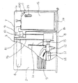
本実施形態の石油ファンヒータを図1、2に示す。石油ファンヒータ本体1は、箱形に形成されたものであって、着脱可能に設けられた前板2と、側面と一体に形成した天板3と、運転動作を操作する操作部4と、温風を吹出す吹出口5と、天板3の上面右側に給油タンク6の出し入れをする開閉自在の蓋7とを備えている。この本体1は、万一、液体燃料が漏れたときにこれを受けるための置台8に載置固定されている。   The oil fan heater of this embodiment is shown in FIGS. The oil fan heater main body 1 is formed in a box shape, and includes a front plate 2 that is detachably provided, a top plate 3 that is formed integrally with a side surface, an operation unit 4 that operates a driving operation, A blowout port 5 through which warm air is blown out and an openable / closable lid 7 for taking in and out the fuel tank 6 are provided on the upper right side of the top plate 3. The main body 1 is mounted and fixed on a mounting base 8 for receiving liquid fuel in the event of leakage.

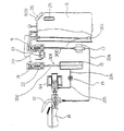
本体1の内部は、図1、2のごとく、タンクガイド11及び仕切板16によって、給油タンク6を収容するタンク収容室1aと、気化器12や電磁ポンプ13等を収容する機能部品収容室1bと、バーナ14や燃焼室15が配置された燃焼部室1cとに区画されている。   As shown in FIGS. 1 and 2, the inside of the main body 1 includes a tank housing chamber 1 a for housing the fuel tank 6 and a functional component housing chamber 1 b for housing the vaporizer 12, the electromagnetic pump 13, and the like by the tank guide 11 and the partition plate 16. And a combustion section chamber 1c in which the burner 14 and the combustion chamber 15 are arranged.

タンク収容室1aには、燃料を一時的に貯える取り外し自在なカートリッジ式の給油タンク6と、給油タンク6の燃料を気化器側に送油する送油経路300と給油タンク6とを着脱自在に接続する送油側接続手段9,10と、気化器12側から燃料ガスを給油タンク6に戻す戻り油経路301と給油タンク6とを着脱自在に接続する戻り油側接続手段21,22とが配置されている。タンク収容室1aの底部には、給油タンク6を収容するときに、接続手段9,10及び21,22にかかる衝撃を吸収・緩和するクッション性のある載置台1dが設けられている。また、タンク収容室1aには、給油タンク6を収容するときに、送油側接続手段9,10及び戻り油側接続手段21,22が確実に嵌合接続するように、ガイド部を形成するのが好適である。   In the tank storage chamber 1a, a removable cartridge-type fuel tank 6 for temporarily storing fuel, and an oil feed path 300 for feeding fuel from the fuel tank 6 to the vaporizer side and the fuel tank 6 are detachable. The oil supply side connection means 9 and 10 to be connected, and the return oil side connection means 21 and 22 for detachably connecting the return oil path 301 for returning the fuel gas from the vaporizer 12 side to the oil supply tank 6 and the oil supply tank 6 are provided. Has been placed. At the bottom of the tank storage chamber 1a, there is provided a mounting table 1d having a cushioning property that absorbs and relieves shock applied to the connecting means 9, 10 and 21, 22 when the fuel tank 6 is stored. Further, a guide portion is formed in the tank storage chamber 1a so that the oil supply side connection means 9, 10 and the return oil side connection means 21, 22 are securely connected when the oil supply tank 6 is stored. Is preferred.

図2に示すように、送油側接続手段は、吸い上げ管と通路を開閉する弁を内蔵した送油ジョイント9と、この送油ジョイント9の弁を受ける送油ジョイント受け10とから構成されている。送油ジョイント受け10には、空気弁20が接続されている。空気弁20は、給油タンク6から電磁ポンプ(送油ポンプ)13へ供給される送油経路300を遮断するために送油経路に空気を取り入れる。この送油ジョイント受け10は、上部が機能部品収容室側に突出したタンクガイド11の壁面に取付けられている。   As shown in FIG. 2, the oil supply side connecting means is composed of an oil supply joint 9 incorporating a suction pipe and a valve for opening and closing the passage, and an oil supply joint receiver 10 for receiving the valve of the oil supply joint 9. Yes. An air valve 20 is connected to the oil feeding joint receiver 10. The air valve 20 takes air into the oil feeding path in order to shut off the oil feeding path 300 supplied from the fuel tank 6 to the electromagnetic pump (oil feeding pump) 13. The oil feeding joint receiver 10 is attached to the wall surface of the tank guide 11 whose upper part protrudes toward the functional component storage chamber.

機能部品収容室1bは、タンク収容室1aと燃焼部室1cとの間に配置される。機能部品収容室1bには、給油タンク6からの燃料を気化する気化器12と、給油タンク6から気化器12に燃料を送る電磁ポンプ13と、気化器12からの未燃焼ガスを溜める貯溜容器18と、気化器12と貯溜容器18との間で未燃焼ガスを冷却する冷却フィン19とが収容されている。   The functional component storage chamber 1b is disposed between the tank storage chamber 1a and the combustion chamber 1c. The functional component storage chamber 1b includes a vaporizer 12 that vaporizes fuel from the fuel tank 6, an electromagnetic pump 13 that sends fuel from the fuel tank 6 to the vaporizer 12, and a storage container that stores unburned gas from the vaporizer 12. 18 and cooling fins 19 for cooling the unburned gas between the vaporizer 12 and the storage container 18 are accommodated.

燃焼部室1cは、仕切板16によって仕切られており、気化器12で気化した燃料ガスと一次燃焼空気とを混合して燃焼するバーナ14と、燃焼するバーナ14を囲む燃焼室15と、バーナ14を収容するバーナボックス17とが収容されている。前記気化器12及びバーナ14等により燃料を燃焼する燃焼部が構成されている。   The combustion chamber 1c is partitioned by a partition plate 16, and a burner 14 that mixes and burns fuel gas vaporized by the vaporizer 12 and primary combustion air, a combustion chamber 15 that surrounds the burner 14 that burns, and a burner 14 And a burner box 17 that accommodates. A combustion section for combusting fuel is constituted by the vaporizer 12 and the burner 14.

送油経路300は、送油ジョイント受け10と電磁ポンプ13を繋ぐ配管203、及び電磁ポンプ13と気化器12とを繋ぐ配管204とを備えている。また、戻り油経路301は、気化器12と冷却フィン19を繋ぐ配管205、冷却フィン19と貯溜容器18を繋ぐ配管206、及び貯溜容器18と戻り油ジョイント受け10を繋ぐ配管207を備えている。これらの配管203〜207はいずれも銅管で成形されている。なお、給油タンク6から電磁ポンプ13までの配管は、銅管以外の樹脂製などの配管を使用してもよい。   The oil feeding path 300 includes a pipe 203 that connects the oil feeding joint receiver 10 and the electromagnetic pump 13, and a pipe 204 that connects the electromagnetic pump 13 and the vaporizer 12. The return oil path 301 includes a pipe 205 that connects the vaporizer 12 and the cooling fin 19, a pipe 206 that connects the cooling fin 19 and the storage container 18, and a pipe 207 that connects the storage container 18 and the return oil joint receiver 10. . These pipes 203 to 207 are all formed of a copper pipe. In addition, piping from resin etc. other than a copper pipe may be used for piping from the oil supply tank 6 to the electromagnetic pump 13.

[給油タンクの構成]
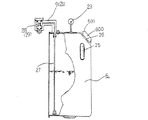
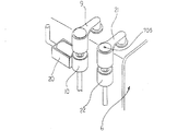
図3は給油タンクの概略図、図4は給油タンクの接続部を示す斜視図、図5は送油ジョイントと給油タンク内の吸上げ管の接続状態を示す断面図、図6は戻り油ジョイントの構造を示す断面図である。
[Composition of oil tank]
3 is a schematic view of a fuel tank, FIG. 4 is a perspective view showing a connecting portion of the fuel tank, FIG. 5 is a cross-sectional view showing a connection state of the oil feeding joint and a suction pipe in the fuel tank, and FIG. 6 is a return oil joint. It is sectional drawing which shows this structure.

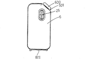
図示のごとく、給油タンク6は、導電性を有する金属製の素材(例えば、亜鉛メッキ鋼鈑)により縦型箱状に形成されたものであって、燃料を入れて持ち運びをするためにタンク上面に設置された取っ手23と、この取っ手23が設けられている上面とこれに隣接する1側面との間に形成された傾斜面501と、この傾斜面501に配置された燃料供給用の給油口26と、この給油口26を開閉回動自在に閉塞する給油キャップ600と、この給油口26に近い側面に設けられ、燃料が給油された状態を視認可能とする油量計25と、取っ手23が設けてある上面において、給油口26と反対側に配置された送油ジョイント9及び戻り油ジョイント21とを備えている。   As shown in the figure, the fuel tank 6 is formed in a vertical box shape from a metal material having conductivity (for example, galvanized steel plate), and the upper surface of the tank is used for carrying fuel. , The inclined surface 501 formed between the upper surface on which the handle 23 is provided and one side surface adjacent thereto, and the fuel supply port disposed on the inclined surface 501 26, an oil supply cap 600 that closes the oil supply port 26 so as to freely open and close, an oil amount meter 25 that is provided on a side surface close to the oil supply port 26 so that the state of fuel supply can be visually confirmed, and a handle 23 Is provided with an oil feeding joint 9 and a return oil joint 21 disposed on the opposite side of the oil supply port 26.

送油ジョイント9は、図5のごとく、給油タンク6の上面からタンク側方に張り出す横L字形の接続管43と、その接続管43の先端に設けられスピンドル方式の弁機構28を内蔵したジョイント本体9aとを備えている。   As shown in FIG. 5, the oil feeding joint 9 includes a horizontal L-shaped connecting pipe 43 projecting from the upper surface of the fuel tank 6 to the side of the tank, and a spindle type valve mechanism 28 provided at the tip of the connecting pipe 43. And a joint body 9a.

ジョイント本体9aは、縦型円筒状に形成され、その下面に送油ジョイント受け10側に嵌合する円筒状の小径突出筒9bが形成され、その外周部に接続シール用のOリング41が外嵌密着されている。また、ジョイント本体9aの上端開口部には、弁機構28を挿入するための開閉可能な蓋ナット38が螺合されている。   The joint main body 9a is formed in a vertical cylindrical shape, and a cylindrical small-diameter protruding cylinder 9b fitted to the oil feeding joint receiver 10 side is formed on the lower surface thereof, and an O-ring 41 for connection sealing is provided on the outer peripheral portion. It fits closely. A lid nut 38 that can be opened and closed for inserting the valve mechanism 28 is screwed into the upper end opening of the joint body 9a.

ジョイント本体9a内の弁機構28は、ジョイント本体9aの小径突出筒9bの中央弁孔9cと、ジョイント本体内の下部に形成された逆円錐形の弁座9dに離着座自在なスピンドル状の弁体31と、この弁体31の上端と蓋ナット38との間に介在され弁体31を閉弁方向に付勢するスプリング35と、弁体31の弁座側周面に嵌着されたシール用Oリング33とを備え、閉弁状態で弁体31の下端が小径突出筒9bから下方に突出した状態となっている。   The valve mechanism 28 in the joint body 9a is a spindle-shaped valve that can be attached to and detached from a central valve hole 9c of the small-diameter protruding cylinder 9b of the joint body 9a and an inverted conical valve seat 9d formed in the lower part of the joint body. A body 31, a spring 35 that is interposed between the upper end of the valve body 31 and the lid nut 38 and biases the valve body 31 in the valve closing direction, and a seal that is fitted to the valve seat side peripheral surface of the valve body 31. The O-ring 33 is provided, and the lower end of the valve element 31 protrudes downward from the small-diameter protruding cylinder 9b when the valve is closed.

接続管43は、その内部にジョイント本体9a内の弁室に連通する吸込み通路43aが形成され、そのタンク側方側に張り出した端部はジョイント本体9aの側部に一体的に接続されている。接続管43の下端部は給油タンク6の上面の挿入穴46からタンク内部に挿通され、下部に形成されたフランジ43bがゴムパッキン50を介して給油タンク6の上面の孔47に螺子により固定されている。接続管43の下端部の外周面には雄螺子が刻設され、この雄螺子に給油タンク内の吸上げ管27の上端が螺着されている。   The connection pipe 43 is formed therein with a suction passage 43a communicating with the valve chamber in the joint body 9a, and an end portion protruding to the tank side is integrally connected to a side portion of the joint body 9a. . The lower end portion of the connecting pipe 43 is inserted into the tank through the insertion hole 46 on the upper surface of the oil tank 6, and a flange 43 b formed at the lower portion is fixed to the hole 47 on the upper surface of the oil tank 6 with a screw through a rubber packing 50. ing. A male screw is formed on the outer peripheral surface of the lower end portion of the connection pipe 43, and the upper end of the suction pipe 27 in the oil supply tank is screwed to the male screw.

吸上げ管27は、給油タンク6の底面近くまで達し、その下端側面に形成された吸込口44に水や塵を通さないフィルターが設けられている。この吸込口44は吸上げ管27の下端底面部に設けてもよい。   The suction pipe 27 reaches near the bottom surface of the fuel tank 6, and a filter that prevents water and dust from passing through the suction port 44 formed on the lower end side surface thereof is provided. The suction port 44 may be provided at the bottom surface of the lower end of the suction pipe 27.

戻り油ジョイント21は、図6のごとく、送油ジョイント9と共に給油タンク6の上面に並設されたものであって、吸上げ管27が接続されていない点、及び給油タンク6の圧力弁機構700を設けている点を除いて、送油ジョイント9と基本的に同様な構造となっている。従って、上記相違点以外の構造については簡単に説明する。   As shown in FIG. 6, the return oil joint 21 is juxtaposed on the upper surface of the oil supply tank 6 together with the oil supply joint 9, the suction pipe 27 is not connected, and the pressure valve mechanism of the oil supply tank 6. The structure is basically the same as that of the oil feeding joint 9 except that 700 is provided. Therefore, the structure other than the above differences will be briefly described.

戻り油ジョイント21は、図6のごとく、給油タンク6の上面からタンク側方に張り出す横L字形の接続管30と、その接続管30の先端に設けられスピンドル方式の弁機構29を内蔵したジョイント本体21aとを備えている。   As shown in FIG. 6, the return oil joint 21 incorporates a horizontal L-shaped connection pipe 30 projecting from the upper surface of the oil supply tank 6 to the side of the tank, and a spindle type valve mechanism 29 provided at the tip of the connection pipe 30. And a joint body 21a.

ジョイント本体21aは、縦型円筒状に形成され、その下面に戻り油ジョイント受け22側に嵌合する円筒状の小径突出筒21bが形成され、その外周部に接続シール用のOリング42が外嵌密着されている。また、ジョイント本体21aの上端開口部には、弁機構29及び圧力弁機構700を挿入するための開閉可能な蓋ナット40が螺合されている。蓋ナット40には、空気孔705が形成されている。   The joint body 21a is formed in a vertical cylindrical shape, and a cylindrical small-diameter protruding cylinder 21b is formed on the lower surface of the joint main body 21a so as to be fitted to the oil joint receiver 22 side. It fits closely. A lid nut 40 that can be opened and closed for inserting the valve mechanism 29 and the pressure valve mechanism 700 is screwed into the upper end opening of the joint body 21a. An air hole 705 is formed in the lid nut 40.

ジョイント本体21a内の弁機構29は、ジョイント本体21aの小径突出筒21bの中央弁孔21cと、ジョイント本体21a内の下部に形成された逆円錐形の弁座21dに離着座自在なスピンドル状の弁体32と、この弁体32を閉弁方向に付勢するスプリング36と、弁体32の弁座側周面に嵌着されたシール用Oリング34とを備えている。   The valve mechanism 29 in the joint body 21a has a spindle-like shape that can be freely attached to and detached from the central valve hole 21c of the small-diameter protruding cylinder 21b of the joint body 21a and the inverted conical valve seat 21d formed in the lower part of the joint body 21a. A valve body 32, a spring 36 that urges the valve body 32 in the valve closing direction, and a sealing O-ring 34 fitted to the valve seat side peripheral surface of the valve body 32 are provided.

弁体32の下端は閉弁状態で小径突出筒21bから下方に突出した状態となっている。また、上端側には、圧力弁機構700の球弁子703を押圧可能な押棒709が一体形成されている。スプリング36は、弁体32の上面と後述する圧力弁機構700の弁座体702の下面との間に介在されている。球弁子703と蓋ナット40との間にばね704が介在されている。   The lower end of the valve body 32 is in a state of protruding downward from the small-diameter protruding cylinder 21b in a closed state. A push rod 709 capable of pressing the ball valve element 703 of the pressure valve mechanism 700 is integrally formed on the upper end side. The spring 36 is interposed between the upper surface of the valve body 32 and the lower surface of a valve seat body 702 of the pressure valve mechanism 700 described later. A spring 704 is interposed between the ball valve element 703 and the lid nut 40.

接続管30は、その内部にジョイント本体21a内の弁室に連通する戻り通路30aが形成され、そのタンク側方側に張り出した端部はジョイント本体21aの側部に一体的に接続されている。接続管30の下端部は給油タンク6の上面の挿入穴48からタンク内部に挿通され、下部に形成されたフランジ30bがゴムパッキン51を介して給油タンク6の上面の孔49に螺子により固定されている。   The connecting pipe 30 is formed therein with a return passage 30a communicating with the valve chamber in the joint main body 21a, and an end portion protruding to the tank side is integrally connected to a side portion of the joint main body 21a. . The lower end portion of the connecting pipe 30 is inserted into the tank through the insertion hole 48 on the upper surface of the fuel tank 6, and the flange 30 b formed at the lower portion is fixed to the hole 49 on the upper surface of the fuel tank 6 with a screw through a rubber packing 51. ing.

給油タンク6は、給油タンク6内に混入した水を検知する水検知手段800および給油タンク6内の燃料の量を検出する燃量検知手段750を備えている。各検知手段750、800からの出力に基づいて制御装置は、燃焼運転を制御する。   The fuel tank 6 includes water detection means 800 that detects water mixed in the fuel tank 6 and fuel amount detection means 750 that detects the amount of fuel in the fuel tank 6. Based on the outputs from the detection means 750 and 800, the control device controls the combustion operation.

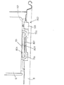
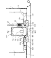
図7〜9に示すように、水検知手段800は、結露した水を溜めるために導電性のタンク底面に設けられた導電性の水受け皿801と、給油タンク6の底部と接触する第1の電極803と、水受け皿801に接触する第2の電極802と、水受け皿801と給油タンク6とを電気的に絶縁する絶縁体としての水密パッキン804とを備え、水受け皿801に貯溜される水と燃料との電気抵抗値の差により水の有無の検知を行うようにされている。第1の電極803は給油タンク6内に設けた電極として、第2の電極802は給油タンク6外に設けた電極として機能し、これら電極間に微電流を流すことにより、水と燃料の電気抵抗値の差を利用して給油タンク6内の水の有無を検出するようになっている。   As shown in FIGS. 7 to 9, the water detection means 800 has a first contact with the bottom of the oil supply tank 6 and a conductive water tray 801 provided on the bottom surface of the conductive tank for collecting condensed water. Water stored in the water tray 801 is provided with an electrode 803, a second electrode 802 that contacts the water tray 801, and a watertight packing 804 as an insulator that electrically insulates the water tray 801 and the fuel tank 6. The presence or absence of water is detected based on the difference in electrical resistance between the fuel and the fuel. The first electrode 803 functions as an electrode provided in the fuel tank 6, and the second electrode 802 functions as an electrode provided outside the fuel tank 6. By flowing a minute current between these electrodes, water and fuel electricity are supplied. The presence or absence of water in the fuel tank 6 is detected using the difference in resistance value.

水受け皿801は、錆びの発生を防止するためにステンレス鋼鈑を用いて給油タンク6と別体で成形されたものである。図9の示すように、水受け皿801の上面側が皿状に凹んだ形状とされ、その外周部に半径方向外側に伸びる周縁フランジ807が形成される。該フランジ807が給油タンク6の底面取付穴805にゴム製のパッキン804を介して取り付けられている。   The water tray 801 is formed separately from the oil supply tank 6 using a stainless steel rod in order to prevent the occurrence of rust. As shown in FIG. 9, the upper surface side of the water tray 801 has a dish-like shape, and a peripheral flange 807 extending radially outward is formed on the outer peripheral portion thereof. The flange 807 is attached to the bottom surface mounting hole 805 of the oil supply tank 6 via a rubber packing 804.

パッキン804は、給油タンク6の底面取付穴805の周壁と、水受け皿801のフランジ807との間に介在された弾性力のある非導電性のものであって、水受け皿801のフランジ807を上下方向から挟み込む。パッキン804は、その下面に配置されたリング状の押さえ部材809及びビス810によってタンク取付穴805の周囲に固定される。これにより、水受け皿801が取付穴805に水密状態で固定される。   The packing 804 is an elastic non-conductive material interposed between the peripheral wall of the bottom surface mounting hole 805 of the fuel tank 6 and the flange 807 of the water tray 801. The packing 804 moves the flange 807 of the water tray 801 up and down. Insert from the direction. The packing 804 is fixed around the tank mounting hole 805 by a ring-shaped pressing member 809 and a screw 810 disposed on the lower surface thereof. As a result, the water tray 801 is fixed to the mounting hole 805 in a watertight state.

このパッキン804は、非導電性で耐油性を有し、かつ撥水性を有するゴム部材から構成される。具体的には耐油性に優れているNBR(アクリルニトリルブタジエンゴム)や撥水性に優れたフッ素ゴムなどが用いられている。特に、パッキンに撥水性が乏しいと、水が溜まり、排水した後でもパッキンと給油タンク6の金属部に水が残った状態になるので、誤動作の要因となるが、本実施形態では、撥水性を有するゴム素材を使用したため、精度良く、正確な水検知が可能となる。   The packing 804 is made of a non-conductive, oil-resistant rubber member having water repellency. Specifically, NBR (acrylonitrile butadiene rubber) excellent in oil resistance and fluorine rubber excellent in water repellency are used. In particular, if the packing has poor water repellency, water accumulates, and water remains in the packing and the metal part of the fuel tank 6 even after draining. Since a rubber material having a water content is used, accurate and accurate water detection becomes possible.

第2の電極802及び第1の電極803は、共に給油タンク6外のタンク載置台1dに取り付けられている。第2の電極802は、水受け皿収容凹部754の底壁からタンク側に突出され、タンク載置状態で水受け皿801の外面に接触する針状電極とされている。第1の電極803は、載置台1dの外周載置面757に露出して、タンク載置状態でタンクの底面6bに接触する針状電極である。両電極802、803を電源に接続することにより、電源から第2の電極802、水受け皿801、その内面の燃料又は水、タンク底面6b、第1の電極803、及び電源に至る電気的な閉回路が構成される。水受け皿801内の液体(燃料および水)の電気抵抗値の差により、水の存在を検知できるようになっている。   Both the second electrode 802 and the first electrode 803 are attached to the tank mounting table 1 d outside the fuel tank 6. The second electrode 802 is a needle-like electrode that protrudes from the bottom wall of the water tray receiving recess 754 to the tank side and contacts the outer surface of the water tray 801 when the tank is placed. The first electrode 803 is a needle electrode that is exposed to the outer peripheral mounting surface 757 of the mounting table 1d and contacts the bottom surface 6b of the tank in the tank mounting state. By connecting both electrodes 802 and 803 to a power source, an electrical closure from the power source to the second electrode 802, water tray 801, fuel or water on its inner surface, tank bottom surface 6b, first electrode 803, and power source. A circuit is constructed. The presence of water can be detected by the difference in electrical resistance values of the liquid (fuel and water) in the water tray 801.

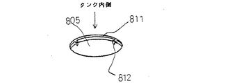
この水検知精度を上げるために、図10に示すように、水受け皿801を取付けるタンク側の取付穴805の穴壁が下方に折曲される。さらに、その折曲部811の周方向の複数箇所に間隔をおいて、細幅状で先端が鋭角とされた針部812が下方に突出形成される。この針部812がタンク側先端電極として機能し、第1の電極803とタンク底面を水受け皿801内の液体を通じて導通路として導通している。なお、給油タンク6内から燃料を吸い上げる吸込口44は、針部812よりも上方に位置しており、水受け皿801内の水を直接吸い込まないようにしている。また、水受け皿801の底面の内側および外側を除いた部分を非導電性の塗料などで被覆することによって、パッキン804と給油タンク6の金属部に水が残った状態になっても誤動作の要因にはならない。   In order to raise this water detection accuracy, as shown in FIG. 10, the hole wall of the mounting hole 805 on the tank side to which the water tray 801 is attached is bent downward. Further, a needle portion 812 having a narrow width and a sharp tip is formed projecting downward at intervals in a plurality of locations in the circumferential direction of the bent portion 811. The needle portion 812 functions as a tank-side tip electrode, and the first electrode 803 and the tank bottom surface are conducted as a conduction path through the liquid in the water tray 801. The suction port 44 that sucks up fuel from the fuel tank 6 is located above the needle portion 812 so that the water in the water tray 801 is not directly sucked. Further, even if water remains in the metal part of the packing 804 and the fuel tank 6 by coating the portions except the inner side and the outer side of the bottom surface of the water tray 801 with a non-conductive paint or the like, it is a cause of malfunction. It will not be.

燃料検知手段750は、図9に示すように、給油タンク6内部に配置されたフロート752と、フロート752に内蔵された磁石751と、磁石751の接近・離間動作に伴いON・OFFするリードスイッチ753とを備えている。   As shown in FIG. 9, the fuel detection means 750 includes a float 752 disposed inside the fuel tank 6, a magnet 751 built in the float 752, and a reed switch that is turned ON / OFF in accordance with the approach / separation operation of the magnet 751. 753.

フロート752は、磁石751を下側に配置した状態で、天蓋付きの透水性筒状ガイド754内に燃料の液面変動に伴って上下動可能に内装されている。ガイド754の下端面は水受け皿801の内面側に一体的に固定されている。リードスイッチ753は、フロート752に対向するように、タンク載置台1dの中央凸部の下面に固定されている。ガイド754は、給油タンク6の燃料を抜くときに市販品の給油ホースがフロート752に接触しないように保護するためのものであり、このガイド754が金属製の場合には内側にバリが発生しない加工が施されている。   The float 752 is housed in a water-permeable cylindrical guide 754 with a canopy in a state where the magnet 751 is disposed on the lower side so as to be movable up and down in accordance with the fuel level fluctuation. The lower end surface of the guide 754 is integrally fixed to the inner surface side of the water tray 801. The reed switch 753 is fixed to the lower surface of the central convex portion of the tank mounting table 1d so as to face the float 752. The guide 754 is for protecting a commercially available oil hose from coming into contact with the float 752 when the fuel in the fuel tank 6 is drained. When this guide 754 is made of metal, no burrs are generated inside. Processing has been applied.

図8に示すように、給油タンク6の装着の有無を検知するタンク装着検知手段900が設けられている。タンク装着検知手段900は、置台8に設置されたマイクロスイッチ901を有し、マイクロスイッチ901は、給油タンク6に当接するとオンする。   As shown in FIG. 8, tank mounting detection means 900 for detecting whether or not the fuel tank 6 is mounted is provided. The tank mounting detection means 900 has a micro switch 901 installed on the pedestal 8, and the micro switch 901 is turned on when contacting the fuel tank 6.

したがって、給油タンク6の内部の燃料が減少して一定の液面水位になると、フロート752の磁石751によりリードスイッチ753が感知動作して、その動作による出力信号を制御装置950に送り、表示部952で燃料切れ等を報知できるようになっている。   Accordingly, when the fuel inside the fuel tank 6 decreases and reaches a certain liquid level, the reed switch 753 performs a sensing operation by the magnet 751 of the float 752, and an output signal due to the operation is sent to the control device 950 to display the display unit. In 952, it is possible to notify that the fuel has run out.

[制御装置の構成]
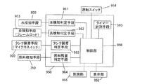
図11に示すように、制御装置950には、CPU、ROM及びRAMを内蔵したマイクロコンピュータから構成され、入力側に炎検知手段953、水検知手段800、タンク装着検知手段900、燃料検知手段750及び運転スイッチ954、室温センサ(図示せず)が接続され、出力側に燃焼部(気化器ヒータ、電磁ポンプ、弁駆動部等の負荷を含む)955、表示部952が接続される。制御装置950は、室温と設定温度に基づき通常の燃焼運転の制御を行うようになっている。
[Configuration of control device]
As shown in FIG. 11, the control device 950 is composed of a microcomputer incorporating a CPU, a ROM and a RAM. The flame detection means 953, the water detection means 800, the tank attachment detection means 900, and the fuel detection means 750 are provided on the input side. Further, an operation switch 954 and a room temperature sensor (not shown) are connected, and a combustion unit (including loads such as a carburetor heater, an electromagnetic pump, and a valve drive unit) 955 and a display unit 952 are connected on the output side. The control device 950 controls normal combustion operation based on the room temperature and the set temperature.

また、制御装置950は、水検知手段800からの信号を受けて水の有無を検知する水検知判定手段961と、炎検知手段953からの信号を受けて炎電流値を設定炎レベルと比較して燃焼状態を検出する炎検知判定手段962と、タンク装着検知手段900からの信号を受けてタンクが装着されたか否かを判定するタンク装着判定手段963と、燃料検知手段750からの信号を受けて燃料の残量が少なくなったことを検知する燃料残量判定手段964と、これらの判定結果、並びに運転スイッチ954及びタイマー計測手段965からの信号を受けて燃焼部955及び表示部952に制御信号を出力する制御部966とを備えている。   In addition, the control device 950 receives a signal from the water detection unit 800 and detects the presence or absence of water, and receives a signal from the flame detection unit 953 and compares the flame current value with the set flame level. Receiving a signal from the flame detection determination means 962 for detecting the combustion state, a tank attachment determination means 963 for receiving a signal from the tank attachment detection means 900 and determining whether or not the tank is attached, and a signal from the fuel detection means 750. The fuel remaining amount determining means 964 that detects that the remaining amount of fuel has decreased, and the determination result and signals from the operation switch 954 and the timer measuring means 965 are received and controlled by the combustion unit 955 and the display unit 952. And a control unit 966 that outputs a signal.

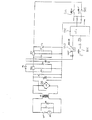
図12は同じくそのアナログ電気回路図である。図示のごとく、この電気回路においては、交流電源ACからトランスTRを介して電源が供給され、この電源をダイオードブリッジDBにより全波整流した後、3端子レギュレータIC2により24V電源の電源を得る。24V電源は、電解コンデンサC5及びフィルムコンデンサC3、C4によって安定化され、炎検知手段953のフレームロッドに供給され、制御装置(IC1)950で炎電流値を検出できるようになっている。さらに、この24V電源から3端子レギュレータIC3により5V電源を得る。5V電源は、電解コンデンサC8及びフィルムコンデンサC6、C7によって安定化され、運転スイッチ954及びタンク装着検知手段900のマイクロスイッチの電源ラインに供給され、制御装置(IC1)950でそのON・OFFが検出できるようになっている。   FIG. 12 is also an analog electric circuit diagram thereof. As shown in the figure, in this electric circuit, power is supplied from an AC power source AC via a transformer TR, and this power source is full-wave rectified by a diode bridge DB, and then a 24-V power source is obtained by a three-terminal regulator IC2. The 24V power supply is stabilized by the electrolytic capacitor C5 and the film capacitors C3 and C4, supplied to the frame rod of the flame detection means 953, and the flame current value can be detected by the control device (IC1) 950. Further, a 5V power source is obtained from the 24V power source by a three-terminal regulator IC3. The 5V power supply is stabilized by the electrolytic capacitor C8 and the film capacitors C6 and C7, supplied to the operation switch 954 and the power supply line of the micro switch of the tank mounting detection means 900, and the controller (IC1) 950 detects the ON / OFF state. It can be done.

そして、制御装置950では、燃料の残量が少なくなったことを検知したとき、燃焼運転を停止するように燃焼部955の制御を行う。また、給油タンク6内に水があることを検知したときでも、燃焼運転を停止しない。燃料残量少を検知したときに、表示部952を通じて水を検知したことおよび燃料切れを報知する。   Then, the control device 950 controls the combustion unit 955 to stop the combustion operation when detecting that the remaining amount of fuel has decreased. Even when it is detected that there is water in the fuel tank 6, the combustion operation is not stopped. When the remaining amount of fuel is detected, the display unit 952 notifies that water has been detected and that fuel has run out.

なお、炎検知手段953における検知動作が水検知手段800における検知動作よりも優先されており、水検知手段800における検知動作は、所定の状態のときのみに限って行われる。すなわち、制御装置950は、運転停止中あるいは運転開始直後の炎の存在しない所定時間のみ、水検知手段800に通電を行って、水検知手段800からの信号を受け付けるようにしている。また、制御装置950は、タンク装着検知手段900からのタンク装着信号を受けてから一定時間は水検知手段800からの信号を受け付けないようにしている。したがって、水検知を限られた期間のみ実行するようにしているので、通電回数が減って、給油タンク6の電触を防止できる。しかも、炎検知手段953および水検知手段800のうちのいずれか一方のみを動作させているので、炎検知手段953および水検知手段800において検知のための回路を構成するアース電極を共有したとしても、その検出精度を高めることができる。図12では、水検知手段800は、炎検知手段953と回路構成の一部を共有しているので、炎が存在しないときのみ、水の有無の検知が可能である。   Note that the detection operation in the flame detection unit 953 is prioritized over the detection operation in the water detection unit 800, and the detection operation in the water detection unit 800 is performed only in a predetermined state. That is, the control device 950 energizes the water detection means 800 only for a predetermined time during which the operation is stopped or immediately after the operation does not have a flame, and receives a signal from the water detection means 800. Further, the control device 950 does not accept a signal from the water detection means 800 for a certain time after receiving the tank attachment signal from the tank attachment detection means 900. Therefore, since water detection is performed only for a limited period, the number of energizations can be reduced and the fuel tank 6 can be prevented from being touched. In addition, since only one of the flame detection means 953 and the water detection means 800 is operated, even if the flame detection means 953 and the water detection means 800 share a ground electrode that constitutes a circuit for detection. The detection accuracy can be increased. In FIG. 12, the water detection unit 800 shares part of the circuit configuration with the flame detection unit 953, and therefore can detect the presence or absence of water only when there is no flame.

図13に示すように、水検知手段800と炎検知手段953とを完全に独立させてもよい。このように独立関係にあるとき、炎の存在に関係なく、常時水の有無の検知が可能となる。すなわち、制御装置950は、運転停止中、運転開始直後の炎の存在しない所定時間、あるいは燃焼中の所定期間のみ、水検知手段800に通電を行って、水検知手段800からの信号を受け付けるようにしている。水有りを検知したとき、このことを表示部952を通じて報知するとともに、燃焼運転を続ける。また、制御装置950は、タンク装着検知手段900からのタンク装着信号を受けてから一定時間は水検知手段800からの信号を受け付けないようにしている。したがって、水検知を限られた期間のみ実行するようにしているので、通電回数が減って、給油タンク6の電触を防止できる。しかも、炎検知手段953および水検知手段800を独立して動作させているので、その検出精度を高めることができる。   As shown in FIG. 13, the water detection means 800 and the flame detection means 953 may be completely independent. Thus, when there is an independent relationship, it is possible to always detect the presence or absence of water regardless of the presence of a flame. That is, the control device 950 energizes the water detection means 800 and accepts a signal from the water detection means 800 only for a predetermined time period during which the flame is not present immediately after the operation is stopped or during a predetermined period during combustion. I have to. When the presence of water is detected, this is notified through the display unit 952 and the combustion operation is continued. Further, the control device 950 does not accept a signal from the water detection means 800 for a certain time after receiving the tank attachment signal from the tank attachment detection means 900. Therefore, since water detection is performed only for a limited period, the number of energizations can be reduced and the fuel tank 6 can be prevented from being touched. Moreover, since the flame detection means 953 and the water detection means 800 are operated independently, the detection accuracy can be increased.

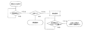
水検知手段800と炎検知手段953とが図12に示すように回路構成を共有する共有関係にある場合、水検知を運転開始直後の炎の存在しない所定時間に行う。図14に示すように、運転スイッチのオンにより燃焼運転が開始されると、最初の点火動作が行われる。このときに水検知を行う。制御部966では、水検知信号を水検知判定手段961で受けたとき、すぐには報知せず、燃焼運転を継続する。その後、燃料の残量少を検知したとき、燃焼部955における電磁ポンプ13の駆動を停止するとともに、水検知状態を表示部952を通じて報知して、給油タンク6内の水抜きをユーザに促す。   When the water detection unit 800 and the flame detection unit 953 share a circuit configuration as shown in FIG. 12, the water detection is performed at a predetermined time immediately after the start of operation where no flame exists. As shown in FIG. 14, when the combustion operation is started by turning on the operation switch, the first ignition operation is performed. At this time, water detection is performed. In the control unit 966, when the water detection signal is received by the water detection determination unit 961, the control unit 966 does not notify immediately but continues the combustion operation. Thereafter, when the remaining amount of fuel is detected, the driving of the electromagnetic pump 13 in the combustion unit 955 is stopped and the water detection state is notified through the display unit 952 to prompt the user to drain the water in the fuel tank 6.

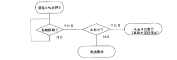
また、図15に示すように、運転スイッチのオンにより燃焼運転が開始されると、制御装置950は、点火動作時に水検知を実行する。その後、点火して炎が発生し、燃焼運転が行われる。水検知手段800が水有りを検知して、水検知信号を水検知判定手段961で受けたとき、制御部966は水検知状態を表示部952を通じて報知する。報知によって給油タンク6内の水抜きをユーザに促すが、燃焼運転は継続される。すなわち、制御装置950は、給油タンク6内に水があることを検知したときでも、燃焼運転を停止せずに、表示部952を通じて水有りを検知したことを報知する。   As shown in FIG. 15, when the combustion operation is started by turning on the operation switch, the control device 950 performs water detection during the ignition operation. Thereafter, ignition is performed to generate a flame, and a combustion operation is performed. When the water detection unit 800 detects the presence of water and receives a water detection signal by the water detection determination unit 961, the control unit 966 notifies the water detection state through the display unit 952. The notification prompts the user to drain the water in the fuel tank 6, but the combustion operation is continued. That is, the control device 950 notifies the presence of water through the display unit 952 without stopping the combustion operation even when it is detected that there is water in the fuel tank 6.

このときの報知は、次回の水検知まで行われる。あるいは、タイマー設定によるタイマー時間の経過や運転スイッチのオフによって燃焼運転が停止するまで行われる。次回の水検知としては、燃焼運転中であっても、温度制御に基づき燃焼を停止する場合があり、このとき炎は存在していないので、水検知を行う。   The notification at this time is performed until the next water detection. Alternatively, it is performed until the combustion operation stops due to the elapse of the timer time set by the timer setting or the operation switch being turned off. As the next water detection, even during the combustion operation, the combustion may be stopped based on the temperature control. At this time, no flame is present, so water detection is performed.

ところで、給油タンク6内の水は、水受け皿801に溜まるので、吸上げ管27から吸い込まれることはない。そのため、燃料がある限り、燃焼運転を継続できる。このように、給油タンク6に燃料を補給した時点ですでに水が混入していても、運転を続け、給油タンク6内の燃料を消費する。燃料が例えば500ccから300cc程度まで残り少なくなったときに、少量の水を抜くことになる。したがって、給油タンク6の重量は軽くなっており、簡単に上下逆にすることができ、水抜き作業を容易に行える。   By the way, the water in the fuel tank 6 is collected in the water tray 801 and is not sucked from the suction pipe 27. Therefore, as long as there is fuel, the combustion operation can be continued. Thus, even if water is already mixed when the fuel is supplied to the fuel tank 6, the operation is continued and the fuel in the fuel tank 6 is consumed. A small amount of water is drained when the remaining fuel is reduced from, for example, about 500 cc to about 300 cc. Therefore, the weight of the fuel tank 6 is light and can be easily turned upside down, so that the water draining operation can be easily performed.

また、水検知動作を必要最小限だけ行うようにしてもよい。制御装置950は、燃焼運転中に燃料残量少を検知したとき、水検知手段800による給油タンク6内の水の有無の検知を行う。給油タンク6内に水があることを検知すると、燃焼運転を停止し、表示部952を通じて水有りを検知したことおよび燃料が少ないことを報知する。   Further, the water detection operation may be performed only as much as necessary. When the remaining amount of fuel is detected during the combustion operation, the control device 950 detects the presence or absence of water in the fuel tank 6 by the water detection means 800. When it is detected that there is water in the fuel tank 6, the combustion operation is stopped, and it is notified through the display unit 952 that water has been detected and that there is little fuel.

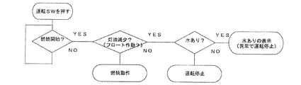
すなわち、図16に示すように、燃焼運転中に、制御部965では、燃料の残量少を検知すると、水検知動作を行う。給油タンク6内の水有りが検知されると、燃焼部955における電磁ポンプ13の駆動を停止するとともに、水検知状態を表示部952を通じて報知して、給油タンク6内の水抜きをユーザに促す。給油タンク6内の水を検知しなかったときには、燃焼運転を停止して、燃料切れを報知する。   That is, as shown in FIG. 16, during the combustion operation, the control unit 965 performs a water detection operation when detecting that the remaining amount of fuel is low. When the presence of water in the fuel tank 6 is detected, the driving of the electromagnetic pump 13 in the combustion unit 955 is stopped, and the water detection state is notified through the display unit 952 to prompt the user to drain the water in the fuel tank 6. . When the water in the fuel tank 6 is not detected, the combustion operation is stopped and a fuel shortage is notified.

なお、水検知動作のタイミングは、燃料残量少を検知した時期以降であれば、いつでもよい。すなわち、燃料残量少を検知したとき、すぐに水検知動作を行う、あるいは燃焼運転の停止と同時に行う。燃料残量少を検知した時点では、燃焼運転中であるが、水検知手段800は、炎検知手段953と独立関係にあれば、水検知できる。共有関係にあっても、燃料残量少を検知したときには、燃焼運転中であるにもかかわらず、水検知できるものとする。   The timing of the water detection operation may be any time as long as it is after the time when the remaining amount of fuel is detected. That is, when the remaining amount of fuel is detected, the water detection operation is performed immediately or simultaneously with the stop of the combustion operation. When the remaining amount of fuel is detected, the combustion operation is in progress, but the water detection means 800 can detect water if it is independent of the flame detection means 953. Even in the shared relationship, when the remaining amount of fuel is detected, water can be detected regardless of the combustion operation.

ところで、水有りの報知は次のような場合に終了する。燃料残量少などの異常によって燃焼運転を停止したときに、運転スイッチがオフされると、報知は終了となる。あるいはタイマー設定されたときのタイマー時間が経過したときに、運転スイッチがオフされることにより、終了となる。   By the way, the notification that there is water ends in the following cases. When the operation switch is turned off when the combustion operation is stopped due to an abnormality such as a small amount of remaining fuel, the notification ends. Alternatively, when the timer time when the timer is set elapses, the operation switch is turned off to end the operation.

以上のようにして、給油タンク6の燃料が少なくなってから、給油タンク6内に水があることを報知するようにすると、水を抜くために、給油タンク6から満タンの灯油を抜く代わりに、約1/10の燃料を抜けばよい。したがって、水抜き作業が容易で使いやすい石油ファンヒータを実現できる。しかも、無駄になる水が混入した燃料も極力少なくすることができる。   As described above, when the fact that there is water in the fuel tank 6 after the fuel in the fuel tank 6 is reduced, in order to drain the water, instead of draining a full tank of kerosene from the fuel tank 6 In addition, about 1/10 of the fuel may be discharged. Therefore, it is possible to realize an oil fan heater that is easy to drain and easy to use. Moreover, it is possible to reduce the amount of fuel mixed with wasted water as much as possible.

なお、本発明は、上記実施形態に限定されるものではなく、本発明の範囲内で上記実施形態に多くの修正および変更を加え得ることは勿論である。例えば、上記実施形態では、取り外し可能な給油タンクにおける水検知について説明したが、この水検知による運転制御は、本体に固定された給油タンクについても適用可能である。   In addition, this invention is not limited to the said embodiment, Of course, many corrections and changes can be added to the said embodiment within the scope of the present invention. For example, in the above-described embodiment, the water detection in the removable fuel tank has been described. However, the operation control based on this water detection can also be applied to the fuel tank fixed to the main body.

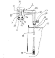
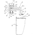
本発明の石油ファンヒータの一部破断正面図The partially broken front view of the oil fan heater of this invention 石油ファンヒータの概略構成図Schematic configuration diagram of oil fan heater 給油タンクの概略図Schematic diagram of oil tank 給油タンクの接続部の斜視図Perspective view of the connection part of the oil tank 送油ジョイントの断面図Cross section of oil feeding joint 戻り油ジョイントの断面図Cross section of return oil joint 給油タンクの側面図Oil tank side view 給油タンクの底部付近を示す図Diagram showing the vicinity of the bottom of the oil tank 給油タンクの水検知手段および燃料検知手段を示す図The figure which shows the water detection means and fuel detection means of a fuel tank 給油タンクの水受け皿取付穴をタンク内部から見た斜視図The perspective view which looked at the water saucer mounting hole of the oil tank from the inside of the tank 制御装置のブロック図Block diagram of control device 石油ファンヒータのアナログ電気回路図Analog electric circuit diagram of oil fan heater 石油ファンヒータの他の形態のアナログ電気回路図Analog electric circuit diagram of other forms of oil fan heater 燃焼運転開始時に水検知を行う場合のフローチャートFlow chart for water detection at the start of combustion operation 燃焼運転開始時に水検知を行う場合の他のフローチャートAnother flowchart for water detection at the start of combustion operation 燃料残量少を検知した後に水検知を行う場合のフローチャートFlowchart for water detection after detecting low fuel level 従来の水検知動作のフローチャートFlow chart of conventional water detection operation

符号の説明Explanation of symbols

6 給油タンク
750 燃料検知手段
800 水検知手段
950 制御装置
952 表示部
953 炎検知手段
955 燃焼部
6 Refueling tank 750 Fuel detection means 800 Water detection means 950 Controller 952 Display unit 953 Flame detection means 955 Combustion part

Claims (11)

燃料を溜める給油タンクと、該給油タンク内に混入した水の有無を検知する水検知手段と、前記給油タンク内の燃料を検知する燃料検知手段と、燃焼運転を制御する制御装置とを備え、該制御装置は、前記燃料検知手段により燃料の残量が少なくなったことが検知されたときに、前記水検知手段により水有りを検知したことを報知することを特徴とする液体燃料燃焼装置。 A fuel tank for storing fuel, water detection means for detecting the presence or absence of water mixed in the fuel tank, fuel detection means for detecting fuel in the fuel tank, and a control device for controlling the combustion operation, The liquid fuel combustion apparatus according to claim 1, wherein when the fuel detection means detects that the remaining amount of fuel is low, the control means notifies that the water detection means detects the presence of water. 燃料を溜める給油タンクと、該給油タンク内に混入した水の有無を検知する水検知手段と、前記給油タンク内の燃料を検知する燃料検知手段と、該燃料検知手段により燃料の残量が少なくなったことが検知され、さらに前記水検知手段により水有りが検知されたとき、燃焼運転を停止する制御装置とを備え、該制御装置は、燃焼運転を停止したときに、前記水検知手段により水有りを検知したことを報知することを特徴とする液体燃料燃焼装置。 A fuel tank for storing fuel, a water detection means for detecting the presence or absence of water mixed in the fuel tank, a fuel detection means for detecting fuel in the fuel tank, and the fuel detection means reduces the remaining amount of fuel. And when the presence of water is detected by the water detection means, the control device stops the combustion operation, and the control device uses the water detection means when the combustion operation is stopped. A liquid fuel combustion apparatus that notifies that water has been detected. 燃料を溜める給油タンクと、該給油タンク内に混入した水の有無を検知する水検知手段と、前記給油タンク内の燃料を検知する燃料検知手段と、燃焼運転を制御する制御装置とを備え、該制御装置は、前記水検知手段により水有りが検知されたとき、前記燃料検知手段により燃料の残量が少なくなったことが検知されるまで、前記水有りを検知したことの報知を禁止することを特徴とする液体燃料燃焼装置。 A fuel tank for storing fuel, water detection means for detecting the presence or absence of water mixed in the fuel tank, fuel detection means for detecting fuel in the fuel tank, and a control device for controlling the combustion operation, When the presence of water is detected by the water detection means, the control device prohibits notification that the presence of water has been detected until the fuel detection means detects that the remaining amount of fuel has decreased. A liquid fuel combustion apparatus. 水検知手段は、燃焼運転中に給油タンク内の水の有無を検知することを特徴とする請求項1〜3のいずれかに記載の液体燃料燃焼装置。 The liquid fuel combustion apparatus according to claim 1, wherein the water detection unit detects the presence or absence of water in the fuel tank during the combustion operation. 水検知手段は、燃料の残量が少なくなったことを検知した後に給油タンク内の水の有無を検知することを特徴とする請求項1〜3のいずれかに記載の液体燃料燃焼装置。 The liquid fuel combustion apparatus according to claim 1, wherein the water detection unit detects the presence or absence of water in the fuel tank after detecting that the remaining amount of fuel has decreased. 水検知手段は、炎検知手段の回路構成の一部を共有し、炎が存在しない燃焼停止中に、給油タンク内の水の有無を検知することを特徴とする請求項1〜3のいずれかに記載の液体燃料燃焼装置。 The water detection means shares a part of the circuit configuration of the flame detection means, and detects the presence or absence of water in the fuel tank during combustion stop when there is no flame. The liquid fuel combustion apparatus described in 1. 燃料を溜める給油タンクと、該給油タンク内に混入した水の有無を検知する水検知手段と、前記給油タンク内の燃料を検知する燃料検知手段と、燃焼運転中の炎の状態を検知する炎検知手段と、燃焼運転を制御する制御装置とを備え、該制御装置は、燃焼運転中に、前記水検知手段により水の有無を検知して、水有りを検知したとき、燃焼運転を続けながら報知することを特徴とする液体燃料燃焼装置。 A fuel tank for storing fuel, a water detection means for detecting the presence or absence of water mixed in the fuel tank, a fuel detection means for detecting fuel in the fuel tank, and a flame for detecting the state of a flame during combustion operation A detection means and a control device for controlling the combustion operation. The control device detects the presence or absence of water by the water detection means during the combustion operation, and continues the combustion operation when the presence of water is detected. A liquid fuel combustion apparatus for informing. 燃料を溜める給油タンクと、該給油タンク内に混入した水の有無を検知する水検知手段と、前記給油タンク内の燃料を検知する燃料検知手段と、燃焼運転中の炎の状態を検知する炎検知手段と、燃焼運転を制御する制御装置とを備え、前記水検知手段は、前記炎検知手段の回路構成の一部を共有し、燃焼運転中には、水の有無の検知を禁止する構成とされ、前記制御装置は、前記水検知手段により水有りを検知したとき、燃焼運転中に報知することを特徴とする液体燃料燃焼装置。 A fuel tank for storing fuel, a water detection means for detecting the presence or absence of water mixed in the fuel tank, a fuel detection means for detecting fuel in the fuel tank, and a flame for detecting the state of a flame during combustion operation A detection unit and a control device for controlling the combustion operation, wherein the water detection unit shares a part of the circuit configuration of the flame detection unit and prohibits detection of the presence or absence of water during the combustion operation The liquid fuel combustion apparatus is characterized in that the control device notifies during combustion operation when the water detection means detects the presence of water. 制御装置は、次回の水検知まで、あるいは燃焼運転を停止するまで水有りを報知し続けることを特徴とする請求項8記載の液体燃料燃焼装置。 The liquid fuel combustion apparatus according to claim 8, wherein the control device continues to notify the presence of water until the next water detection or until the combustion operation is stopped. 制御装置は、燃焼運転を開始するときに水の有無の検知を行うことを特徴とする請求項8または9記載の液体燃料燃焼装置。 The liquid fuel combustion apparatus according to claim 8 or 9, wherein the control device detects the presence or absence of water when the combustion operation is started. 給油タンクは、上面側から燃料を送出する構造とされ、水検知手段は、前記給油タンクの底面に設けられたことを特徴とする請求項1〜10のいずれかに記載の液体燃料燃焼装置。 11. The liquid fuel combustion apparatus according to claim 1, wherein the fuel tank is configured to deliver fuel from an upper surface side, and water detection means is provided on a bottom surface of the fuel tank.
JP2004226799A 2004-03-09 2004-08-03 Liquid fuel combustion equipment Pending JP2005291690A (en)

Priority Applications (1)

Application Number Priority Date Filing Date Title
JP2004226799A JP2005291690A (en) 2004-03-09 2004-08-03 Liquid fuel combustion equipment

Applications Claiming Priority (2)

Application Number Priority Date Filing Date Title
JP2004065042 2004-03-09
JP2004226799A JP2005291690A (en) 2004-03-09 2004-08-03 Liquid fuel combustion equipment

Publications (1)

Publication Number Publication Date
JP2005291690A true JP2005291690A (en) 2005-10-20

Family

ID=35324807

Family Applications (1)

Application Number Title Priority Date Filing Date
JP2004226799A Pending JP2005291690A (en) 2004-03-09 2004-08-03 Liquid fuel combustion equipment

Country Status (1)

Country Link
JP (1) JP2005291690A (en)

Similar Documents

Publication Publication Date Title
US6135427A (en) Humidifier
US6035699A (en) Water leakage detection apparatus
JPH0892780A (en) Water electrolysis gas generator
KR940004117B1 (en) Water purifier
US20210212287A1 (en) Heated animal water supply container
JP3880777B2 (en) Liquid fuel combustion equipment
JP4109699B2 (en) Liquid fuel combustion equipment
JP3942348B2 (en) Liquid fuel combustion equipment
JP4809125B2 (en) Liquid supply device, humidifier equipped with liquid supply device, and heater equipped with liquid supply device
US6895990B1 (en) Water heater fail safe apparatus
CN110409534A (en) A kind of fuel tank with drainage arrangement
KR100546545B1 (en) Liquid fuel combustion device
CN214199009U (en) Humidifier
JP3948895B2 (en) Liquid fuel combustion equipment
KR20110082677A (en) Purifier compounded humidifier
KR20150140952A (en) Electrostatic capacitance type device for detecting liquid level
KR200284623Y1 (en) Electric steam generator of wall mounted type
JP2010181040A (en) Oil strainer with water detection
JP2003106515A (en) Liquid fuel combustion device
JP2519956Y2 (en) Liquid container liquid amount detector
KR200263656Y1 (en) Warning device for liquid measure
GB2205858A (en) Generating a mixture of oxygen and hydrogen electrolytically
KR20230166360A (en) Humidifier and control method the same
KR100237248B1 (en) Fuel Tank Auto Water Dispenser
JPS6222756Y2 (en)