JP2005291637A - Floor heater unit - Google Patents
Floor heater unit Download PDFInfo
- Publication number
- JP2005291637A JP2005291637A JP2004108629A JP2004108629A JP2005291637A JP 2005291637 A JP2005291637 A JP 2005291637A JP 2004108629 A JP2004108629 A JP 2004108629A JP 2004108629 A JP2004108629 A JP 2004108629A JP 2005291637 A JP2005291637 A JP 2005291637A
- Authority
- JP
- Japan
- Prior art keywords
- sheet
- plate
- floor
- heating
- unit
- Prior art date
- Legal status (The legal status is an assumption and is not a legal conclusion. Google has not performed a legal analysis and makes no representation as to the accuracy of the status listed.)
- Pending
Links
- 238000010438 heat treatment Methods 0.000 claims abstract description 86
- 238000005338 heat storage Methods 0.000 claims abstract description 16
- 229910052751 metal Inorganic materials 0.000 claims abstract description 12
- 239000002184 metal Substances 0.000 claims abstract description 12
- 239000011232 storage material Substances 0.000 claims description 9
- 229920003002 synthetic resin Polymers 0.000 claims description 9
- 239000000057 synthetic resin Substances 0.000 claims description 9
- 239000000843 powder Substances 0.000 claims description 4
- 229920005992 thermoplastic resin Polymers 0.000 claims description 2
- 239000004020 conductor Substances 0.000 claims 1
- 239000002023 wood Substances 0.000 claims 1
- 238000010276 construction Methods 0.000 description 12
- 238000000034 method Methods 0.000 description 6
- XLYOFNOQVPJJNP-UHFFFAOYSA-N water Substances O XLYOFNOQVPJJNP-UHFFFAOYSA-N 0.000 description 6
- OKTJSMMVPCPJKN-UHFFFAOYSA-N Carbon Chemical compound [C] OKTJSMMVPCPJKN-UHFFFAOYSA-N 0.000 description 3
- 241000617482 Kiwa Species 0.000 description 3
- 239000002390 adhesive tape Substances 0.000 description 3
- 238000010586 diagram Methods 0.000 description 3
- 238000009408 flooring Methods 0.000 description 3
- 229910002804 graphite Inorganic materials 0.000 description 3
- 239000010439 graphite Substances 0.000 description 3
- 238000009826 distribution Methods 0.000 description 2
- 230000000694 effects Effects 0.000 description 2
- 238000005485 electric heating Methods 0.000 description 2
- 239000000463 material Substances 0.000 description 2
- 239000004570 mortar (masonry) Substances 0.000 description 2
- 239000002245 particle Substances 0.000 description 2
- 238000002791 soaking Methods 0.000 description 2
- FGRBYDKOBBBPOI-UHFFFAOYSA-N 10,10-dioxo-2-[4-(N-phenylanilino)phenyl]thioxanthen-9-one Chemical compound O=C1c2ccccc2S(=O)(=O)c2ccc(cc12)-c1ccc(cc1)N(c1ccccc1)c1ccccc1 FGRBYDKOBBBPOI-UHFFFAOYSA-N 0.000 description 1
- RYGMFSIKBFXOCR-UHFFFAOYSA-N Copper Chemical compound [Cu] RYGMFSIKBFXOCR-UHFFFAOYSA-N 0.000 description 1
- 239000006096 absorbing agent Substances 0.000 description 1
- 229910052782 aluminium Inorganic materials 0.000 description 1
- XAGFODPZIPBFFR-UHFFFAOYSA-N aluminium Chemical compound [Al] XAGFODPZIPBFFR-UHFFFAOYSA-N 0.000 description 1
- 210000000038 chest Anatomy 0.000 description 1
- 229910052802 copper Inorganic materials 0.000 description 1
- 239000010949 copper Substances 0.000 description 1
- 230000003247 decreasing effect Effects 0.000 description 1
- 230000001747 exhibiting effect Effects 0.000 description 1
- 239000006260 foam Substances 0.000 description 1
- 238000007689 inspection Methods 0.000 description 1
- 238000009434 installation Methods 0.000 description 1
- 239000011810 insulating material Substances 0.000 description 1
- 238000010030 laminating Methods 0.000 description 1
- 230000007774 longterm Effects 0.000 description 1
- 238000012423 maintenance Methods 0.000 description 1
- 238000004519 manufacturing process Methods 0.000 description 1
- 229910001120 nichrome Inorganic materials 0.000 description 1
- 239000011120 plywood Substances 0.000 description 1
- 230000005855 radiation Effects 0.000 description 1
- 239000002994 raw material Substances 0.000 description 1
- 230000035939 shock Effects 0.000 description 1
- 229920001169 thermoplastic Polymers 0.000 description 1
- 239000004416 thermosoftening plastic Substances 0.000 description 1
Images


Landscapes
- Central Heating Systems (AREA)
- Surface Heating Bodies (AREA)
Abstract
Description
本発明は、厚板を扱うように取扱うことができる床暖房装置ユニットの改良に関し、床構造板上に敷設し、ネジ釘などの固定具で簡単に着脱でき、また、配線も容易な床暖房装置ユニットに関する。 The present invention relates to an improvement of a floor heating device unit that can be handled like a thick plate, and is laid on a floor structure plate, can be easily attached and detached with a fixing tool such as a screw nail, and wiring is easy. The apparatus unit.
床暖房装置は、電気加熱式のものとガスで加熱した温水を流通させた加熱するガス加熱式のものとがある。 The floor heating device includes an electric heating type and a gas heating type that heats hot water heated by gas.
電気加熱式の装置は、1)発泡合成樹脂板などの断熱板の上に形成された蛇行状の溝内にニクロム線を内蔵させた発熱ケーブル(発熱体)を配置したもの、2)発熱パターン(発熱体)に形成した金属板を合成樹脂絶縁シートに積層した発熱シートを使用したもの、更に、3)一定温度において抵抗が急上昇する特性(いわゆるPTC効果)を持つ熱可塑性合成樹脂からなる面状発熱シートを使用したものがある。 The electric heating type equipment is 1) a heating cable (heating element) with a nichrome wire built in a meandering groove formed on a heat insulating plate such as a foamed synthetic resin plate, and 2) a heating pattern. A surface made of a thermoplastic synthetic resin having a characteristic (so-called PTC effect) in which resistance rapidly increases at a constant temperature, using a heat generating sheet obtained by laminating a metal plate formed on (heating element) on a synthetic resin insulating sheet. Some of them use a sheet-like heat generating sheet.
前記1)と2)の床暖房装置は、温度制御のために複数個の温度センサーを所定の場所に設ける必要があり、その温度センサーが配置されている場所にタンスや敷物などの放熱を阻害する家具が配置された場合は温度が異常に上昇し、場合によっては火災を発生させる危険性がある。また、この種の発熱体に釘などの金属が打ち込まれた時にはショートや電気ショックや漏電事故につながる可能性があり、最近は次第に使用されなくなっている。 The floor heating devices of 1) and 2) above require that a plurality of temperature sensors be provided in a predetermined place for temperature control, and the heat radiation from the chiffon and the rug is obstructed at the place where the temperature sensors are arranged. If furniture is placed, the temperature will rise abnormally and in some cases there is a risk of fire. In addition, when a metal such as a nail is driven into this type of heating element, there is a possibility of causing a short circuit, an electric shock or an electric leakage accident.
3)PTC効果を持つ発熱シートは、あたかも発熱シート面の全面に温度センサーを有するような温度制御機能を発揮して作動する極めて安全な装置であることが長年の使用実績で証明されている。そしてこれには下記のように特許文献1、2及び3などの多数の公知文献で提案されている。
3) The heat generating sheet having the PTC effect has been proven by many years of use to be an extremely safe device that operates by exhibiting a temperature control function as if having a temperature sensor on the entire surface of the heat generating sheet. This has been proposed in a number of known documents such as
更に、温水加熱式床暖房装置は、断熱材の上面に蛇行する溝を形成し、この溝内に合成樹脂製パイプあるいは銅パイプを配管し、屋外などに別に設置した温水(熱媒体を含む)ボイラと前記パイプを接続して温水を前記床暖房装置に供給する装置である。この床暖房装置は、ガス加熱による温水を熱源としているので、安全性が高い上に暖房コストが安いことから大量に普及されてきた。 Furthermore, the hot water heating type floor heating device forms a meandering groove on the upper surface of the heat insulating material, and a synthetic resin pipe or a copper pipe is provided in the groove, and the hot water (including the heat medium) is installed separately outdoors. It is an apparatus which connects a boiler and the said pipe and supplies warm water to the said floor heating apparatus. Since this floor heating apparatus uses hot water by gas heating as a heat source, it has been widely used because of its high safety and low heating cost.
しかし、この温水加熱式床暖房装置は、暖房開始時に急速に加熱できないこと、また、温度ムラが発生し易いこと、更に、ボイラやパイプの寿命が8年程度で比較的短く、短期間内に装置を更新する必要がある。しかし、この時点では室内の様子はかなり変化し、例えば床の上に大形の家具が配置されている場合が多く、従って、その部屋の生活を一時的に中断して工事しなければならないなどの問題がある。
「特許文献1」に記載された発明は、面状発熱シートを合成樹脂製カバー内に封入して一昼夜の期間放置することにより、このカバーの外形変化を観察してカバーにピンホールがなく、従って空気がカバー内に入っていないことを確認した後にモルタル中に埋設するもので、コンクリート床構造内に面状発熱シートを設置する典型的なものである。
In the invention described in “
また、「特許文献2」に記載された発明は、和室を床暖房にするもので、根太に支持される鍔を両側に持つチャンネル部材を準備し、このチャンネル部材を2本の根太の間に支持させておいて、その内部に面状発熱シートや蓄熱材などを収容するものであるが、これは床面近くに根太が存在する家の暖房装置に適用できるものである。
The invention described in “
更に、「特許文献3」に記載された発明は、断面がコ字形の特殊なチャンネルを準備し、このチャンネルの中に面状発熱シートと蓄熱材を配置した床暖房装置である。
Furthermore, the invention described in “
前記3件の発明は、面状発熱シートをコンクリート床構造内に埋め込むことが前提であったり、特殊断面形状のチャンネルを使用し、これを床構造の構成部材として配置し、更に、このチャンネルの中にヒーター等を配置して暖房装置を構成するものである。 The three inventions described above are based on the premise that the sheet heating sheet is embedded in the concrete floor structure, or a channel having a special cross-sectional shape is used and disposed as a structural member of the floor structure. A heater or the like is arranged therein to constitute a heating device.
前記特許文献1の床暖房装置の場合は、コンクリート床面に面状発熱シートを配置し、更にその上にコンクリート層を形成する必要がある。従って、一旦、モルタルが硬化すると、この発熱シートを直接点検したり、外観観察することができず、不幸にして通電が不能となった場合は、コンクリート床を破壊して点検修理する煩雑で大がかりな作業が必要である。
In the case of the floor heating device of
また、特許文献2及び3に記載された発明は、面状発熱シートや蓄熱材を収容するために特殊な断面形状に形成されたチャンネル部材が必要であり、この部材の中に面状発熱シートなどを組み込んで床構造を形成するものであるので、特別にそのチャンネル部材の製作が必要である。更に、これを使用した床構造は、当然、専門技術を持つ作業員による組立て作業が必要であり、製作コストが高くなる上に、メンテナンスも同様に専門技術者が行わなければならない。
In addition, the inventions described in
前記のように、従来の床暖房装置は床構造そのものの改良が必要であり、従って、新築家屋の場合には予めその床構造を採用しておくことが可能であるが、後付け的に既設の床を加工するためには、長期にわたる工事が必要である。 As described above, the conventional floor heating apparatus needs to be improved in the floor structure itself. Therefore, in the case of a new house, it is possible to adopt the floor structure in advance. Long-term construction is required to process the floor.
従って、例えば、使用中の部屋を1日、あるいは半日だけ工事に使用して迅速に工事を完成させることは全くできない。つまり、家屋の床構造の改良と床暖房装置の両方の工事が必要であったのである。 Therefore, for example, it is impossible to complete a construction quickly by using a room in use for construction for one day or half a day. In other words, both the improvement of the floor structure of the house and the construction of the floor heating system were necessary.
従来の構造の床暖房装置は、前記のように床構造の工事と床暖房装置の設置工事、そしてこの床暖房装置の上部に床材(フローリング)を敷設する工事などが必要であることから、コンクリート床などのコンクリート工事者と、発熱体を結線する電気配線工事者と、更に床板を組付ける工事者などの一連の専門技術者が必要となる。 Since the floor heating device of the conventional structure requires the construction of the floor structure and the installation of the floor heating device as described above, and the construction of laying the flooring (flooring) on the top of this floor heating device, etc. A series of specialized engineers such as a concrete worker such as a concrete floor, an electric wiring worker who connects heating elements, and a worker who assembles a floor board are required.
しかも、これらの各種の作業が連続して行なわれない場合はその工事に長い期間が必要となる。特に、既に長い間使用されてワックス掛けされた手入れの良い建物のフローリングは、そこの住人には愛着がある。従って、この床板を引き剥がし、前記のような床暖房装置を組付けるための各種の工事はなかなか踏み切れないものがある。 Moreover, if these various operations are not performed continuously, a long period is required for the work. In particular, the flooring of well-maintained buildings that have already been used and waxed for a long time is attached to the residents. Therefore, various works for peeling off the floor board and assembling the floor heating apparatus as described above are difficult to complete.
例えば、部屋の模様替えとして、カーペットが気にいらなくなったり、不要となった場合は、これを交換したり廃棄すれば済むことであるから、このような作業は、住み慣れた家の居住者でも比較的受け入れ易い。このような背景を考慮すると、例えば、現在使用中の部屋の床板を気にいった木質ないし模様のものと交換する作業、更に好ましくはこの床板の交換と共に発熱シート(面状発熱体)を床構造内に構成することで、暖房がなかった部屋を簡単に暖房床に模様替えをすることができれば、普通の部屋を床暖房装置付きの部屋に大きく模様換えすることができる。 For example, if a carpet becomes unpleasant or no longer needed as a redesign of a room, it can be replaced or discarded. easy. In consideration of such a background, for example, the work of replacing the floorboard of the room currently in use with a wooden or pattern of interest, and more preferably, the heating sheet (planar heating element) is replaced in the floor structure along with the replacement of the floorboard. With this configuration, if a room without heating can be easily changed to a heated floor, a normal room can be greatly changed to a room with a floor heating device.
最近、リースの対象品が増えているが、この対象となる品目は、各種の事務機器から航空機などの大型の装置に至るまで、殆んどの動産が対象となっている。従って、暖房カーペットをリース対象品とすることも可能であるのに対して建物の付属設備や構築物等は不動産であることから原則としてリースの対象外である。 Recently, the number of items subject to leasing has increased, but the items covered are almost all movable properties ranging from various office equipment to large-scale devices such as aircraft. Therefore, heating carpets can be leased items, but buildings are not subject to leasing because they are real estate.
もし、床暖房装置を一体化されたユニットを使用して簡単に組立て、これを部屋に設置でき、更に必要に応じて撤去できるもの、つまり動産として扱うことができるものはリースの対象品とすることが可能である。 If the floor heating device can be easily assembled using an integrated unit, installed in the room, and can be removed if necessary, that is, it can be treated as movable property, it is the subject of lease. It is possible.
本発明は、床構造板の上、あるいは平坦に仕上げられたコンクリート床面上に敷設したボードなどの床構造板の上に、厚目の板材のように取扱って敷設して床暖房装置を形成するための床暖房装置ユニット(以下、単にユニットという)を提供するものである。 The present invention forms a floor heating device by handling and laying it like a thick board on a floor structure board such as a board laid on a floor structure board or on a flat concrete floor surface. A floor heating device unit (hereinafter simply referred to as a unit) is provided.
前記目的を達成するための本発明に係る「ユニット」は次のように構成されている。 The “unit” according to the present invention for achieving the above object is configured as follows.
1)上面に所定間隔で平行に小根太を有するベースプレートと、この小根太の間に配置とされた面状発熱体と平板状の蓄熱体と、更に前記蓄熱体の上面を覆い、小根太に固定される上板と、この上板に沿って配置される金属板とからなる暖房床組立体からなり、この組立体は床構造板に対して固定手段によって着脱可能に固定されるように構成されていることを特徴としている。 1) A base plate having small joists in parallel at a predetermined interval on the upper surface, a planar heating element and a flat plate heat storage element disposed between the small joists, and further covering the upper surface of the heat accumulator, The heating floor assembly includes a fixed upper plate and a metal plate disposed along the upper plate, and the assembly is configured to be detachably fixed to the floor structure plate by a fixing means. It is characterized by being.
2)ユニットに内蔵する蓄熱体は、合成樹脂シートからなる袋の内部に、多孔性の板体からなる骨材と蓄熱材が収容されたことを特徴としている。 2) The heat storage body built in the unit is characterized in that an aggregate made of a porous plate and a heat storage material are accommodated in a bag made of a synthetic resin sheet.
3)前記上板と金属板とは一体的に形成されていることを特徴としている。 3) The upper plate and the metal plate are integrally formed.
前記ユニットは、次のように施工するのが好ましい。 The unit is preferably constructed as follows.
上面に所定間隔で平行に小根太を有するベースプレートと、前記小根太の間に配置とされた面状発熱体と平板状の蓄熱体と、更に前記小根太の間の蓄熱体の上面を覆い、小根太に固定される上板と、金属板とからなるユニットを床構造板に固定手段によって着脱可能に固定する工程、前記面状発熱体の配線を行う工程、更に、前記ユニットの上に床板を固定する工程からなることを特徴としている。 Covering the upper surface of the base plate having the small joists parallel to the upper surface at a predetermined interval, the planar heating element and the flat plate heat storage element arranged between the small joists, and further between the small joists, A step of detachably fixing a unit composed of an upper plate fixed to the small joists and a metal plate to the floor structure plate by a fixing means, a step of wiring the planar heating element, and a floor plate on the unit It is characterized by comprising a step of fixing.
また、一つの暖房室内に設けられた床構造板上に、前記暖房室の周囲の少なくとも一部にダミープレートを配置し、このダミープレートの内側にユニットを敷設し、このユニットの面状発熱体と給電装置との間を配線する工程と、前記ユニットを床構造板上にネジ釘などの着脱可能な固定手段で前記ユニットを床構造板上に固定する工程と、前記ユニットの上に床板を配置し、これを固定する工程と、前記ダミープレートの縁部を覆うように壁面に幅木を固定する工程とからなることを特徴としている。 In addition, a dummy plate is disposed on at least a part of the periphery of the heating room on a floor structure plate provided in one heating room, and a unit is laid inside the dummy plate. Wiring between the power supply device and the unit, fixing the unit on the floor structure plate with a detachable fixing means such as a screw nail on the floor structure plate, and placing the floor plate on the unit And a step of fixing the base plate to the wall surface so as to cover the edge of the dummy plate.
本発明に係るユニットは、1枚の厚板状に構成されており、その内部に面状発熱ヒーターや蓄熱材を収容して完成体となっているので、単にこれを暖房室の床構造板上に敷いて配線し、更に床板を敷くことにより施工が完成することから、タンスや棚のような家具、システムキッチンなどを建物に取付けるように、簡単に取付けることができる。また、少しの部分を分解して検査し、更に取外したり、交換することも可能である。 The unit according to the present invention is configured as a single thick plate, and a sheet heating heater and a heat storage material are accommodated inside the unit to form a finished body. Since the construction is completed by laying and wiring on the floor, and further laying the floorboard, it can be easily installed like furniture and system kitchens such as chests and shelves. It is also possible to disassemble and inspect a small part and then remove or replace it.
また、ユニットを家電製品のように工場において製造し、運搬し、倉庫へ収納あるいは搬出することが簡単にできる。そして、ユニットを床構造板上に敷設して固定し、配線し、更に床板をユニットの上面に好みの床板を敷設するだけで床暖房装置が完成する。 In addition, the unit can be easily manufactured in a factory like a home appliance, transported, and stored or taken out to a warehouse. And a floor heating apparatus is completed only by laying and fixing a unit on a floor structure board, wiring, and also laying a floor board of choice on the upper surface of a unit.
このように、組立型の家電製品のように取扱うことができるので、リースの対象品とすることもできる。 In this way, since it can be handled like an assembly-type home appliance, it can also be a product to be leased.
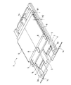
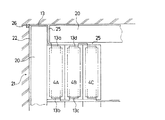
図1は、本発明に係る床暖房装置を構成するユニット(暖房床組立体)の構成の斜視図、図2は同正断面図、図3は図2に対応する一部切開した平面図である。 1 is a perspective view of a configuration of a unit (heating floor assembly) constituting a floor heating device according to the present invention, FIG. 2 is a front sectional view thereof, and FIG. 3 is a partially cut plan view corresponding to FIG. is there.
1は、2枚の面状発熱シート4を組込んだユニットを示しており、例えば合成樹脂発泡体からなる断熱性の板材からなるベースプレート2の上面に、狭い幅の小根太3aと、この幅の2倍の幅を持つ小根太3を所定の幅に配置する。
1 shows a unit in which two sheet-like
そして3本の小根太3、3aの間に2枚の面状発熱シート4(PTC特性を持つもの)と2枚の蓄熱材5を上下に積層する。そして下面に金属板(薄く、厚手の金属箔のようなアルミシート、均熱シート)6を貼った薄いベニヤ板からなる蓋板7を載せ、必要に応じてベースプレート2から蓋板7とをネジクギなどの固定部材で分解可能に接合して一体化して小組立ユニットF1とする。
Then, two sheet heating sheets 4 (having PTC characteristics) and two
次に、前記蓋板7の上面に両面接着テープ8によって床板9(フロア材)を貼付けて一体化して大組立ユニットF2を形成する。
Next, a floor plate 9 (floor material) is adhered to the upper surface of the
本発明においては、前記小組立ユニットF1を、下記する暖房室の床構造板上にネジクギなどの固定部材で固定し、最後に蓋板7上に貼着されていた両面接着テープ8の離型シートを剥離して任意の床板9を実加工10、10aを嵌合させながら次々に接着して床構造を完成する第1の施工法を実施する。また、大組立ユニットF2を床構造板上に、床板9の実加工10、10aを嵌合させながら組立てる第2の施工法を実施する2つの工法がある。
In the present invention, the small assembly unit F1 is fixed on a floor structure plate of a heating room to be described below with a fixing member such as a screw thread, and finally the mold release of the double-sided
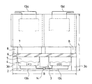
図3に示すように、2枚の面状発熱シート4(イ)の一方の配線13aを供給側とすると、反対側の出口側の配線13bと、平行して配置されている他の面状発熱シート4(ロ)の配線13cをコネクタ14で結合する。そしてこの配線13cの反対側の配線13dを隣接する面状発熱シート4の供給側の配線と結合する。
As shown in FIG. 3, when one
このように配線13bと13cをベースプレート2上に収納する構成を採用すると、ユニットの設置が容易となり、更に現場での配線を効率的に行うことができる。
If the configuration in which the
図3におけるベースプレート2の幅Bと長さLとは、暖房する室内に合わせて製造する必要があることから、建築の基準である(尺)を利用する。例えば、幅Bを600mm(2尺)、長さLを1820mm(6尺)などとする。この尺に近い寸法を採用することによって面状発熱シート4を2枚、4枚あるいは6枚使用したユニット1とすることができる。
Since the width B and the length L of the
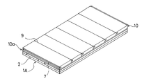
図4は2枚の面状発熱シート4を使用したユニット1A(大組立ユニット)の斜視図であって、この例においては3枚の床板9を連結して小組立ユニットの上に配置している。
FIG. 4 is a perspective view of a
また、図5は4枚の面状発熱シート4を使用したユニット1B(大組立ユニット)を示しており、図4のユニット1Aのベースプレート2を2枚使用し、蓋板7aと床板9aを図4のものの2場合の幅を持つものを使用して組立ている。このように、ベースプレート2の幅を変更すると共に面状発熱シート4の枚数を変更することによって各種のユニット1とすることができる。
(床暖房装置の組立工程)
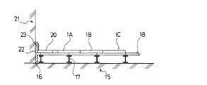
床暖房装置を施工する際の準備工程として、図6に示す如く部屋Rのコンクリート床15の周囲にキワ根太16を配置する。そしてこのキワ根太16と支持脚17(足先となる緩衝体と、長さを調節できるボルトと、パーチクルボードの小片からなる受け板で構成される)をパーチクルボードからなる置き床18の所定の位置にネジ釘で固定しながら、前記コンクリート床15より所定間隔hだけ上げた状態で部屋R全体に置き床18を配置する。
FIG. 5 shows a
(Assembling process of floor heating system)
As a preparatory process when constructing the floor heating apparatus, as shown in FIG. 6,
図1及び図6に示す符号1A、1B、1Cは、本発明において採用したユニット(小組立ユニット)を示しており、小根太3、3aを所定の位置に配置したベースプレート2と、この小根太3、3aの間に面状発熱シート4と蓄熱材5を収容し、更に、前記小根太3、3aの上に、均熱板として作用する金属板6を下面に積層した蓋体7を配置して構成している。
そしてこの蓋板7から小根太3、3aまでネジクギを螺入して全体を1枚の厚板の状態に組立てる。この場合、前記の如く、1枚のベースプレート2と2枚の面状発熱体5を単位とするユニット1(小組立ユニット)を構成している。前記の如く、このベースプレート2の幅を2倍3倍と変更することによって異なる寸法のモジュル化された暖房床組立体として、部屋の大きさなどを考慮した構造の床暖房装置とすることができる。
Then, screws are screwed from the
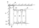
図6に示す如く部屋Rの周囲にはダミープレート19、20を配置し、これの内側に本発明に係るユニット1を敷設しており、前記ダミープレートの部分を非発熱部となっている。このダミープレート19、20と壁21との間に「間隙22」が形成されているが、この間隙22はユニット1の位置の調整をしたり、ユニット1を交換する際にこれをずらすための作業部分としたり、あるいは内部の面状発熱シート4などの電気的な検査を行う際の作業空間でもある。そして、この間隙22は壁面に固定される幅木23によってその上方を閉止して仕上げされる。
As shown in FIG. 6,
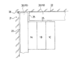
図7の平面図に示す如く、部屋Rの周囲にダミープレート20(19)とユニット(この場合、小組立ユニット)1A、1B、1Cを配置する。そしてこのこのユニットを所定の位置に置いた状態で前記ダミープレート20、19をユニットの側面に合わせる。この場合、壁21とダミープレート20(19)との間に間隙22が形成される。前記ダミープレート20(19)とユニット1A、1B、1Cとの間に、配線用間隙25が形成されている。また、26は分電盤である。
As shown in the plan view of FIG. 7, a dummy plate 20 (19) and units (in this case, small assembly units) 1A, 1B, 1C are arranged around the room R. The
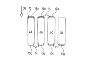
図8は複数枚の面状発熱シート4A、4B、4Cと分電盤26との間を配線13した状態の配線図である。そして図9と図10は配線13を終了した状態と、ダミープレート20と壁21との間の間隙22を幅木23で閉止した状態を示す図である。
FIG. 8 is a wiring diagram in a state in which
図11は、4枚の面状発熱シート4A・・4Dを配線13a・・13gで配線した状態を示している。この図より分かるように、隣接して配置されている面状発熱シート4A、4B、4C、4Dの電極線同士がコネクタ14を使用して連結されている。この面状発熱シートの一方の端部に配線されるのではなく、両端部に側に、あたかも蛇行するように配線される。このような構成を採用すると、配線用間隙25における配線の交差を防止することができ、配線事故の発生を防止できる。
FIG. 11 shows a state in which the four
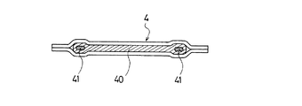
図12は、本発明の面状発熱シート4の断面図であって、この面状発熱シート4は、例えば特許第1232594号公報(特公昭55−31598号公報)に記載された技術によって得ることができるものであり、その原料は熱可塑性樹脂に黒鉛の微粉末を添加して成形して面状発熱シート本体40としたもので、その両端に電極線41を配置している。
FIG. 12 is a cross-sectional view of the
この面状発熱シート本体40は特殊な構造をしており、その表面に黒鉛微粉末が偏って導電層を形成し、中間部は黒鉛微粉末が多く存在せず、ほぼ電気絶縁状態である。そしてこの面状発熱シートは、温度上昇と共に電気抵抗が次第に増加し、そしてある温度以上になると、極端に電気抵抗が増加する性質があり、その結果、前記温度において電流の流れが阻止され、温度が自然に低下する性質、即ち、PTC特性を持っている。
This sheet heating sheet
この面状発熱シート本体40には、2本の電極線41の間の発熱シートの部分を電流が流れることになる。つまり、電流は2本の電極に直交するように流れて発熱する性質を持っている。従って、この面状発熱シート4A、4B、4C、4Dと連結しても、その電極線41の間に形成されている発熱部をを流れる電流に変わりがない(つまり、直列抵抗にはならない)ことから、前記図11に示したように見かけ上は直列の配線を方法を採用することによって約50m位の長さに連結しても、十分に給電でき、各面状発熱シートを一斉に発熱させることが可能である。
In the sheet heat generating sheet
なお、本発明において使用する面状発熱シートの消費電力としては、20cm幅のもので1mあたり60W、30cm幅が100W、45cm幅が120Wである。 The power consumption of the sheet-like heat generating sheet used in the present invention is 20 W in width, 60 W per meter, 30 cm in width 100 W, and 45 cm in width 120 W.
1 暖房床組立体(ユニット) 2 ベースプレート
3、3a 小根太 4 面状発熱シート
5 蓄熱材 6 金属板 7 蓋板
8 両面接着テープ 9 床板(フロア材)
10、10a 実加工 14 コネクタ
15 コンクリート床 16 キワ根太
17 支持脚 18 置き床
19、20 ダミープレート 21 壁
22 間隙 23 幅木
25 配線用間隙 26 電源
DESCRIPTION OF
10, 10a
Claims (4)
The floor heating device unit according to claim 1, wherein the upper plate is a thin wooden plate, and the metal plate is a thin plate that does not act as a strength member, and these are integrally laminated.
Priority Applications (1)
| Application Number | Priority Date | Filing Date | Title |
|---|---|---|---|
| JP2004108629A JP2005291637A (en) | 2004-04-01 | 2004-04-01 | Floor heater unit |
Applications Claiming Priority (1)
| Application Number | Priority Date | Filing Date | Title |
|---|---|---|---|
| JP2004108629A JP2005291637A (en) | 2004-04-01 | 2004-04-01 | Floor heater unit |
Publications (1)
| Publication Number | Publication Date |
|---|---|
| JP2005291637A true JP2005291637A (en) | 2005-10-20 |
Family
ID=35324756
Family Applications (1)
| Application Number | Title | Priority Date | Filing Date |
|---|---|---|---|
| JP2004108629A Pending JP2005291637A (en) | 2004-04-01 | 2004-04-01 | Floor heater unit |
Country Status (1)
| Country | Link |
|---|---|
| JP (1) | JP2005291637A (en) |
Cited By (6)
| Publication number | Priority date | Publication date | Assignee | Title |
|---|---|---|---|---|
| JP2008051422A (en) * | 2006-08-25 | 2008-03-06 | Matsushita Electric Works Ltd | Floor-heating device and its remodeling method |
| JP2009103352A (en) * | 2007-10-23 | 2009-05-14 | Misawa Homes Co Ltd | Heat storage floor structure and heat storage floor construction method |
| JP2009168253A (en) * | 2008-01-10 | 2009-07-30 | Nasakoa Kk | Floor heating panel unit |
| JP2010127576A (en) * | 2008-11-28 | 2010-06-10 | Panasonic Electric Works Co Ltd | Heating panel |
| KR101713162B1 (en) * | 2016-03-31 | 2017-03-07 | 주식회사 히트업 | A prefabricatde heating floor and fabricating method thereof |
| JP2022131516A (en) * | 2021-02-26 | 2022-09-07 | 三菱ケミカルインフラテック株式会社 | Heating floor |
-
2004
- 2004-04-01 JP JP2004108629A patent/JP2005291637A/en active Pending
Cited By (7)
| Publication number | Priority date | Publication date | Assignee | Title |
|---|---|---|---|---|
| JP2008051422A (en) * | 2006-08-25 | 2008-03-06 | Matsushita Electric Works Ltd | Floor-heating device and its remodeling method |
| JP2009103352A (en) * | 2007-10-23 | 2009-05-14 | Misawa Homes Co Ltd | Heat storage floor structure and heat storage floor construction method |
| JP2009168253A (en) * | 2008-01-10 | 2009-07-30 | Nasakoa Kk | Floor heating panel unit |
| JP2010127576A (en) * | 2008-11-28 | 2010-06-10 | Panasonic Electric Works Co Ltd | Heating panel |
| KR101713162B1 (en) * | 2016-03-31 | 2017-03-07 | 주식회사 히트업 | A prefabricatde heating floor and fabricating method thereof |
| JP2022131516A (en) * | 2021-02-26 | 2022-09-07 | 三菱ケミカルインフラテック株式会社 | Heating floor |
| JP7596855B2 (en) | 2021-02-26 | 2024-12-10 | 三菱ケミカルインフラテック株式会社 | Heated floor |
Similar Documents
| Publication | Publication Date | Title |
|---|---|---|
| JP7025535B2 (en) | Thermal panel and heating system | |
| EP3884213B1 (en) | A panel and an electrical end connector, a method for coupling of panels and a heating system | |
| KR20240027066A (en) | Plasterboard-like building panel radiant heater | |
| US2932711A (en) | Radiant heating panel and construction for buildings and the like | |
| JP2005291637A (en) | Floor heater unit | |
| JP4485844B2 (en) | Floor heating system construction method | |
| GB2493013A (en) | Electric heating system assembly comprising a thermally conductive panel and a heating wire | |
| US20110155716A1 (en) | Stone panel | |
| KR101975227B1 (en) | Prefabricated electric flooring panel | |
| JP2006045783A (en) | Electrothermal building material, electrothermal wall heating device, electrothermal floor heating device and construction method | |
| US20220018549A1 (en) | Protected infrared wall panel heating with flexible heating fabric | |
| JP2006046047A (en) | Honeycomb core floor member for floor heating | |
| US20180283701A1 (en) | Heating tile with raised channels | |
| US20200205236A1 (en) | Grooved Floor Underlayment for Radiant Heat | |
| JP3801593B2 (en) | Double floor heating system using planar heating element and metal floor panel | |
| JPH11132482A (en) | Floor-heating structure | |
| JP2006299505A (en) | Floor heating system making use of composite panel | |
| JP3604369B2 (en) | Floor heating panel | |
| KR102773441B1 (en) | Electric heat tile | |
| JP7460112B2 (en) | Heat generating structure | |
| KR101975226B1 (en) | Electric flooring panel | |
| GB2414910A (en) | Integrated heat generating membrane | |
| JP2002081161A (en) | Hot-air floor heating sleeper | |
| US9989264B2 (en) | Heating tile | |
| JP2006292311A (en) | Floor heating system |
Legal Events
| Date | Code | Title | Description |
|---|---|---|---|
| A625 | Written request for application examination (by other person) |
Effective date: 20060125 Free format text: JAPANESE INTERMEDIATE CODE: A625 |
|
| A711 | Notification of change in applicant |
Effective date: 20060626 Free format text: JAPANESE INTERMEDIATE CODE: A712 |
|
| A977 | Report on retrieval |
Free format text: JAPANESE INTERMEDIATE CODE: A971007 Effective date: 20080206 |
|
| A131 | Notification of reasons for refusal |
Free format text: JAPANESE INTERMEDIATE CODE: A131 Effective date: 20080304 |
|
| A521 | Written amendment |
Effective date: 20080502 Free format text: JAPANESE INTERMEDIATE CODE: A523 |
|
| A131 | Notification of reasons for refusal |
Effective date: 20080527 Free format text: JAPANESE INTERMEDIATE CODE: A131 |
|
| A02 | Decision of refusal |
Free format text: JAPANESE INTERMEDIATE CODE: A02 Effective date: 20081014 |