JP2005291636A - Lubricating device - Google Patents
Lubricating device Download PDFInfo
- Publication number
- JP2005291636A JP2005291636A JP2004108592A JP2004108592A JP2005291636A JP 2005291636 A JP2005291636 A JP 2005291636A JP 2004108592 A JP2004108592 A JP 2004108592A JP 2004108592 A JP2004108592 A JP 2004108592A JP 2005291636 A JP2005291636 A JP 2005291636A
- Authority
- JP
- Japan
- Prior art keywords
- pressure
- fuel
- remaining amount
- detected
- liquid fuel
- Prior art date
- Legal status (The legal status is an assumption and is not a legal conclusion. Google has not performed a legal analysis and makes no representation as to the accuracy of the status listed.)
- Pending
Links
- 230000001050 lubricating effect Effects 0.000 title abstract 4
- 239000000446 fuel Substances 0.000 claims abstract description 325
- 239000007788 liquid Substances 0.000 claims abstract description 132
- 238000001514 detection method Methods 0.000 claims description 88
- 238000005086 pumping Methods 0.000 claims description 23
- 238000012937 correction Methods 0.000 claims description 19
- 230000007423 decrease Effects 0.000 claims description 7
- 239000002828 fuel tank Substances 0.000 abstract description 51
- XLYOFNOQVPJJNP-UHFFFAOYSA-N water Substances O XLYOFNOQVPJJNP-UHFFFAOYSA-N 0.000 description 39
- 239000007921 spray Substances 0.000 description 17
- 238000002485 combustion reaction Methods 0.000 description 11
- 238000010586 diagram Methods 0.000 description 5
- 238000009434 installation Methods 0.000 description 4
- 230000002411 adverse Effects 0.000 description 3
- 230000008030 elimination Effects 0.000 description 3
- 238000003379 elimination reaction Methods 0.000 description 3
- 239000007789 gas Substances 0.000 description 3
- 238000000034 method Methods 0.000 description 3
- 238000005452 bending Methods 0.000 description 2
- 238000006243 chemical reaction Methods 0.000 description 2
- 238000012790 confirmation Methods 0.000 description 2
- 238000012935 Averaging Methods 0.000 description 1
- 230000005540 biological transmission Effects 0.000 description 1
- 239000000567 combustion gas Substances 0.000 description 1
- 238000004891 communication Methods 0.000 description 1
- 230000008602 contraction Effects 0.000 description 1
- 230000003247 decreasing effect Effects 0.000 description 1
- 238000009795 derivation Methods 0.000 description 1
- 238000010438 heat treatment Methods 0.000 description 1
- 238000012545 processing Methods 0.000 description 1
- 230000010349 pulsation Effects 0.000 description 1
- 238000005507 spraying Methods 0.000 description 1
- 238000013022 venting Methods 0.000 description 1
Images
Landscapes
- Feeding And Controlling Fuel (AREA)
Abstract
Description
本発明は、燃料貯留手段に貯留されている液体燃料の残量を検知可能な給油装置に関するものである。 The present invention relates to a fuel supply device capable of detecting the remaining amount of liquid fuel stored in a fuel storage means.
従来より、給湯装置や熱源装置のような液体燃料を燃焼する装置類には、下記特許文献1に開示されているように、燃料タンクと、これに接続された燃料配管に設置された圧力センサとを有し、この圧力センサの検知信号に基づいて液体燃料の残量を検知する給油装置が採用されている。
上記特許文献1に開示されている燃焼装置で採用されている給油装置は、液体燃料の残量に基づく圧力を燃料流路の中途に設けた圧力センサによって検知し、残量を検知するものである。かかる構成の給油装置は、燃料流路を千鳥状に構成するなどして、燃料流路の中途に空気等の気体が残存するいわゆるエア咬み状態が発生しやすい状態で使用されると、燃料流路の中途に残存する空気等の膨張収縮に伴って圧力センサの検知精度が低下し、残量を正確に検知できないおそれがある。上記特許文献1に開示されている給油装置では、エア咬み状態に伴う残量の検知精度の低下を防止するために別途エア抜き装置を設け、残量の誤検知を防止している。そのため、上記特許文献1に開示されている給油装置は、残量を比較的精度良く検知可能であるが、装置構成が複雑になってしまうという問題があった。上記特許文献1の給油装置は、装置構成が複雑であるため、設置作業や初期設定に手間がかかるという問題があった。 The fueling device employed in the combustion device disclosed in Patent Document 1 detects a pressure based on the remaining amount of liquid fuel by a pressure sensor provided in the middle of the fuel flow path, and detects the remaining amount. is there. When the fuel supply device having such a configuration is used in a state in which a so-called air biting state in which a gas such as air remains in the middle of the fuel flow path by configuring the fuel flow path in a staggered manner, the fuel flow The detection accuracy of the pressure sensor decreases with the expansion and contraction of air or the like remaining in the middle of the road, and the remaining amount may not be detected accurately. In the fueling device disclosed in Patent Document 1, a separate air venting device is provided to prevent a decrease in detection accuracy of the remaining amount due to the air biting state, thereby preventing erroneous detection of the remaining amount. For this reason, the fueling device disclosed in Patent Document 1 can detect the remaining amount with relatively high accuracy, but has a problem that the configuration of the device becomes complicated. The oil supply device of Patent Document 1 has a problem that the installation work and the initial setting are troublesome because the device configuration is complicated.
そこで、本発明は、装置構成が簡略で、液体燃料の残量を的確に報知可能な給油装置の提供を目的とする。 Accordingly, an object of the present invention is to provide a fuel supply device that has a simple device configuration and can accurately notify the remaining amount of liquid fuel.
上記した課題を解決すべく提供される請求項1に記載の発明は、液体燃料を貯留する燃料貯留手段と、当該燃料貯留手段に貯留されている液体燃料に基づく圧力を検知する圧力検知手段と、当該圧力検知手段によって検知される圧力に基づいて燃料貯留手段内に貯留されている液体燃料の残量を検知する残量検知手段とを備えており、当該残量検知手段は、所定のタイミングで検知される液体燃料の残量を検知基準残量として認識し、当該検知基準残量を基準として燃料の残量を検知するものであり、前記検知基準残量は、残量検知手段によって検知される残量が、先に設定されている検知基準残量よりも増加することを条件として当該増加後の残量に更新されることを特徴とする給油装置である。 The invention according to claim 1, which is provided to solve the above-described problem, includes a fuel storage unit that stores liquid fuel, and a pressure detection unit that detects a pressure based on the liquid fuel stored in the fuel storage unit. And a remaining amount detecting means for detecting the remaining amount of the liquid fuel stored in the fuel storing means based on the pressure detected by the pressure detecting means, and the remaining amount detecting means has a predetermined timing. The remaining amount of liquid fuel detected in step 1 is recognized as a detection reference remaining amount, and the remaining amount of fuel is detected based on the detection reference remaining amount. The detection reference remaining amount is detected by a remaining amount detection means. The fuel supply device is characterized in that it is updated to the increased remaining amount on condition that the remaining amount to be increased is greater than the previously set detection reference remaining amount.
本発明の給油装置のように液体燃料を取り扱う給油装置では、燃料貯留手段と圧力検知手段との間に空気層等の気体が残存するいわゆるエア咬みが発生することがある。この場合、圧力検知手段によって検知される圧力は、エア咬みがない場合に検知される圧力から空気層等の分だけ変動したものであり、液体燃料の貯留量に起因する圧力を正確に検知したものではない。しかし、エア咬み状態が変動しない限りは、液体燃料の残量と、圧力検知手段によって検知される圧力との間には一定の相関関係があるため、残量検知手段により検知される液体燃料の残量は正確である。 In a fuel supply apparatus that handles liquid fuel like the fuel supply apparatus of the present invention, a so-called air bite in which a gas such as an air layer remains between the fuel storage means and the pressure detection means may occur. In this case, the pressure detected by the pressure detection means fluctuates by an amount corresponding to the air layer or the like from the pressure detected when there is no air bite, and the pressure caused by the amount of liquid fuel stored is accurately detected. It is not a thing. However, as long as the air bite state does not fluctuate, there is a certain correlation between the remaining amount of liquid fuel and the pressure detected by the pressure detecting means, so the liquid fuel detected by the remaining amount detecting means The remaining amount is accurate.
一方、上記したエア咬みが解消すると、エア咬み時における液体燃料の残量と、圧力検知手段によって検知される圧力との相関関係が崩れる。そのため、エア咬み時に設定された検知基準残量に基づいてエア咬み状態が解消された後も残量検知を行うと、残量検知手段によって検知される残量が先に認識されている検知基準残量を超えてしまうものと想定される。本発明の給油装置では、残量検知手段によって検知されている残量が先に設定されている検知基準残量よりも増加することを条件としてエア咬みが解消した可能性があると判断され、液体燃料の残量検知の基準となる検知基準残量の更新が行われる。そのため、本発明の給油装置によれば、エア咬みの有無にかかわらず液体燃料の残量を正確に検知できる。 On the other hand, when the above-described air bite is eliminated, the correlation between the remaining amount of liquid fuel at the time of air bite and the pressure detected by the pressure detection unit is lost. Therefore, if the remaining amount is detected even after the air bite state is resolved based on the detection reference remaining amount set at the time of air biting, the detection criterion in which the remaining amount detected by the remaining amount detecting means is recognized first. It is assumed that the remaining amount will be exceeded. In the fueling device of the present invention, it is determined that there is a possibility that the air bite has been resolved on the condition that the remaining amount detected by the remaining amount detecting means increases from the previously set detection reference remaining amount, The detection reference remaining amount serving as a reference for detecting the remaining amount of liquid fuel is updated. Therefore, according to the fueling device of the present invention, the remaining amount of liquid fuel can be accurately detected regardless of the presence or absence of the air bite.
本発明の給油装置は、エア咬みの有無にかかわらず液体燃料の残量を正確に検知できるため、エア咬みを解消するための新たな構成を必要としない。そのため、本発明によれば、給油装置の装置構成を単純化しつつ、十分な残油量の検知精度を有する給油装置を提供できる。 Since the fuel supply device of the present invention can accurately detect the remaining amount of liquid fuel regardless of the presence or absence of air bite, a new configuration for eliminating the air bite is not required. Therefore, according to the present invention, it is possible to provide an oil supply device having a sufficient residual oil amount detection accuracy while simplifying the device configuration of the oil supply device.
請求項2に記載の発明は、検知基準残量が、燃料貯留手段に液体燃料が所定量貯留されている際に残量検知手段によって検知される液体燃料の残量として認識されることを特徴とする請求項1に記載の給油装置である。
The invention according to
本来、燃料貯留手段に所定量の液体燃料が貯留されている場合、残量検知手段によって検知される残量は一定である筈である。しかし、燃料貯留手段と圧力検知手段との間に空気層等が残存したエア咬み状態の解消前後では、例え液体燃料の残量が同一であっても圧力検知手段によって検知される圧力が異なる。そのため、エア咬みの解消後における液体燃料の残量の検知を、エア咬みの解消前に設定された検知基準残量に基づいて行うと、液体燃料の残量が誤検知されてしまう。本発明の給油装置では、燃料貯留手段に液体燃料が所定量貯留されている際に残量検知手段によって検知される液体燃料の残量を検知基準残量として採用し、これを基準として残量の検知が行われる。そのため、本発明の給油装置によればエア咬みの有無にかかわらず液体燃料の残量を正確に検知できる。 Originally, when a predetermined amount of liquid fuel is stored in the fuel storage means, the remaining amount detected by the remaining amount detection means should be constant. However, before and after the air biting state in which an air layer or the like remains between the fuel storage unit and the pressure detection unit, the pressure detected by the pressure detection unit is different even if the remaining amount of liquid fuel is the same. For this reason, if the detection of the remaining amount of the liquid fuel after the elimination of the air bite is performed based on the detection reference remaining amount set before the elimination of the air bite, the remaining amount of the liquid fuel is erroneously detected. In the fueling device of the present invention, the remaining amount of liquid fuel detected by the remaining amount detecting means when a predetermined amount of liquid fuel is stored in the fuel storing means is adopted as the detection reference remaining amount, and the remaining amount is based on this. Is detected. Therefore, according to the fueling device of the present invention, the remaining amount of liquid fuel can be accurately detected regardless of the presence or absence of air bite.
請求項3に記載の発明は、残量検知手段が検知する残量が所定の変化率以上変動することを条件として、燃料貯留手段に液体燃料を補充する補充動作が行われたことを検知し、当該補充動作の完了後に残量検知手段によって検知される液体燃料の残量が、検知基準残量として認識されることを特徴とする請求項1又は2に記載の給油装置である。 The invention according to claim 3 detects that the replenishment operation for replenishing the fuel storage means with liquid fuel is performed on condition that the remaining amount detected by the remaining amount detection means fluctuates by a predetermined change rate or more. 3. The fueling device according to claim 1, wherein the remaining amount of liquid fuel detected by the remaining amount detecting means after completion of the replenishment operation is recognized as a detection reference remaining amount.
かかる構成によれば、補充動作の有無を的確に検知し、検知基準残量を最適化することができる。従って、本発明によれば、燃料貯留手段と圧力検知手段との間におけるエア咬みの有無にかかわらず液体燃料の残量を正確に検知可能な給油装置を提供できる。 According to this configuration, it is possible to accurately detect the presence or absence of the replenishment operation and optimize the detection reference remaining amount. Therefore, according to the present invention, it is possible to provide a fuel supply device that can accurately detect the remaining amount of liquid fuel regardless of whether or not there is an air bite between the fuel storage means and the pressure detection means.
請求項4に記載の発明は、残量検知手段によって検知される残量が所定の報知基準残量以下になることを条件として報知動作を行う報知手段を有し、残量検知手段は、検知する残量が所定の変化率以上変動することを条件として燃料貯留手段に対する液体燃料の補給動作が行われたものと認識し、当該補給動作における液体燃料の補給前に圧力検知手段によって検知された基準圧力に相当する残量に基づいて前記報知基準残量を設定することを特徴とする請求項1乃至3のいずれかに記載の給油装置である。 According to a fourth aspect of the present invention, there is provided notification means for performing a notification operation on condition that the remaining amount detected by the remaining amount detection means is equal to or less than a predetermined notification reference remaining amount. Recognizing that the liquid fuel supply operation to the fuel storage means was performed on condition that the remaining amount fluctuates by a predetermined change rate or more, and detected by the pressure detection means before the liquid fuel supply in the supply operation The fuel supply device according to any one of claims 1 to 3, wherein the notification reference remaining amount is set based on a remaining amount corresponding to a reference pressure.
本発明の給油装置は、補給動作が行われる直前の液体燃料の残量に基づいて報知基準残量が設定され、液体燃料の残量がこの報知基準残量に達すると報知動作を行うものである。そのため、本発明の給油装置によれば、液体燃料の補給時期を的確に報知することができる。 The refueling device of the present invention sets a notification reference remaining amount based on the remaining amount of liquid fuel immediately before the replenishment operation is performed, and performs a notification operation when the remaining amount of liquid fuel reaches the notification reference remaining amount. is there. Therefore, according to the fueling device of the present invention, it is possible to accurately notify the replenishment timing of the liquid fuel.
請求項5に記載の発明は、燃料貯留手段に貯留されている液体燃料が流れる燃料流路の中途に、液体燃料を圧送する燃料圧送手段が設けられており、残量検知手段により検知される残量は、燃料圧送手段が動作することを条件として燃料圧送手段の作動前後における残量検知手段の検知残量の変動量に基づいて補正されることを特徴とする請求項1乃至4のいずれかに記載の給油装置である。 According to the fifth aspect of the present invention, a fuel pumping unit that pumps the liquid fuel is provided in the middle of the fuel flow path through which the liquid fuel stored in the fuel storage unit flows, and is detected by the remaining amount detecting unit. 5. The remaining amount is corrected based on a fluctuation amount of a detected remaining amount of the remaining amount detecting unit before and after the operation of the fuel pumping unit on condition that the fuel pumping unit operates. It is the oil supply apparatus of crab.
液体燃料が流れる燃料流路の中途に燃料圧送手段が設けられている場合は、圧力検知手段が検知する圧力が燃料圧送手段の動作の影響を受けて変動し、液体燃料の残量検知に悪影響を及ぼす可能性がある。本発明の給油装置では、燃料圧送手段が動作することを条件として燃料の残量が補正されるため、液体燃料の残量を正確に検知することができる。 When the fuel pumping means is provided in the middle of the fuel flow path through which the liquid fuel flows, the pressure detected by the pressure detecting means fluctuates due to the influence of the operation of the fuel pumping means and adversely affects the detection of the remaining amount of liquid fuel. May affect. In the fueling device of the present invention, the remaining amount of fuel is corrected on condition that the fuel pumping unit operates, so that the remaining amount of liquid fuel can be accurately detected.
請求項6に記載の発明は、液体燃料を貯留する燃料貯留手段と、当該燃料貯留手段に貯留されている液体燃料に基づく圧力を検知する圧力検知手段と、当該圧力検知手段によって検知される圧力に基づいて燃料貯留手段内に貯留されている液体燃料の残量を検知する残量検知手段と、圧力検知手段によって検知される検知圧力が所定の報知基準圧力以下になることを条件として報知動作を行う報知手段とを備えており、前記残量検知手段が、燃料貯留手段が空あるいは液体燃料の残量が所定量以下であると想定される場合に圧力検知手段によって検知される検知圧力を基準圧力として検出し、当該基準圧力よりも所定の補正圧力だけ高い圧力を報知基準圧力と認識することを特徴とする給油装置である。
The invention according to
本発明の給油装置では、燃料貯留手段が空であったり液体燃料の残量が所定量以下である場合に検知される検知圧力が基準圧力として認識され、この基準圧力よりも所定の補正圧力分だけ高い報知基準圧力が報知動作の基準となる。そのため、上記した構成によれば、燃料貯留手段が空あるいは所定量となる以前に報知動作を行うことが可能な給油装置を提供できる。 In the fueling device of the present invention, the detected pressure that is detected when the fuel storage means is empty or the remaining amount of liquid fuel is less than or equal to a predetermined amount is recognized as the reference pressure, and a predetermined correction pressure amount is obtained from this reference pressure. A notification reference pressure that is as high as the reference is the reference for the notification operation. Therefore, according to the above-described configuration, it is possible to provide a fuel supply device capable of performing a notification operation before the fuel storage unit is empty or reaches a predetermined amount.
上記したように、本発明の給油装置では、空であったり液体燃料の残量が所定量以下である場合に検知される検知圧力が基準圧力として認識されるため、エア咬みの発生や解消があっても報知動作を的確に行える。 As described above, in the fueling device of the present invention, the detected pressure that is detected when the fuel is empty or the remaining amount of liquid fuel is equal to or less than the predetermined amount is recognized as the reference pressure. Even if it exists, the notification operation can be performed accurately.
請求項7に記載の発明は、燃料貯留手段に貯留されている液体燃料が流れる燃料流路の中途に、液体燃料を圧送する燃料圧送手段が設けられており、燃料圧送手段が動作することを条件として燃料圧送手段の作動に伴う圧力検知手段の検知圧力の変化量に基づいて報知基準圧力が補正されることを特徴とする請求項4乃至6のいずれかに記載の給油装置である。 According to the seventh aspect of the present invention, fuel pumping means for pumping liquid fuel is provided in the middle of the fuel flow path through which the liquid fuel stored in the fuel storage means flows, and the fuel pumping means operates. The fuel supply device according to any one of claims 4 to 6, wherein the notification reference pressure is corrected based on a change amount of the detected pressure of the pressure detecting means accompanying the operation of the fuel pumping means as a condition.
上記したように、液体燃料が流れる燃料流路の中途に燃料圧送手段が設けられている場合は、圧力検知手段が検知する圧力が燃料圧送手段の動作の影響を受けて変動し、液体燃料の残量検知に悪影響を及ぼす可能性がある。本発明の給油装置では、燃料圧送手段が動作することを条件として報知基準圧力が補正されるため、報知動作を的確に行える。 As described above, when the fuel pumping means is provided in the middle of the fuel flow path through which the liquid fuel flows, the pressure detected by the pressure detecting means fluctuates due to the influence of the operation of the fuel pumping means, and the liquid fuel There is a possibility of adversely affecting the remaining amount detection. In the fueling device of the present invention, the notification reference pressure is corrected on condition that the fuel pumping unit operates, so that the notification operation can be performed accurately.
請求項8に記載の発明は、残量検知手段が、燃料貯留手段が空あるいは液体燃料の残量が所定量以下であることが認識される時点よりも所定時間以上前に圧力検知手段によって検知される検知圧力を基準圧力として検出することを特徴とする請求項4乃至7のいずれかに記載の給油装置である。 According to the eighth aspect of the present invention, the remaining amount detecting means is detected by the pressure detecting means more than a predetermined time before the time when it is recognized that the fuel storage means is empty or the remaining amount of liquid fuel is less than the predetermined amount. The oil supply device according to any one of claims 4 to 7, wherein the detected pressure is detected as a reference pressure.
本発明の給油装置は、燃料貯留手段が空あるいは所定量以下であることが認識される以前に圧力検知手段によって検知された検知圧力が基準圧力として設定されるものであるため、燃料貯留手段が空あるいは所定量以下となる前に確実に報知動作を行える。 In the fueling device of the present invention, since the detected pressure detected by the pressure detecting means before the fuel storing means is recognized to be empty or less than a predetermined amount is set as the reference pressure, the fuel storing means The notification operation can be performed reliably before it becomes empty or less than a predetermined amount.
請求項9に記載の発明は、残量検知手段が検知する残量が所定の変化率以上変動することを条件として、燃料貯留手段への液体燃料の補充動作が行われたことを検知し、当該補充動作以前に圧力検知手段によって検知される検知圧力を基準圧力として検出することを特徴とする請求項4乃至8のいずれかに記載の給油装置である。 The invention according to claim 9 detects that the replenishment operation of the liquid fuel to the fuel storage means has been performed on condition that the remaining amount detected by the remaining amount detection means fluctuates more than a predetermined change rate, The oil supply device according to any one of claims 4 to 8, wherein a detection pressure detected by the pressure detection means before the replenishment operation is detected as a reference pressure.
かかる構成によれば、燃料貯留手段が空となったこと、あるいは、液体燃料の残量が所定量以下となったことを的確に検知し、基準圧力を適正値に設定することができる。従って、本発明によれば、燃料貯留手段が空あるいは所定量以下となる前に確実に報知動作を行える。 According to such a configuration, it is possible to accurately detect that the fuel storage means is emptied or that the remaining amount of liquid fuel is equal to or less than a predetermined amount, and the reference pressure can be set to an appropriate value. Therefore, according to the present invention, the notification operation can be reliably performed before the fuel storage means is empty or becomes less than a predetermined amount.
請求項10に記載の発明は、残量検知手段が、他の装置への液体燃料の供給停止時に検知される燃料の残量が減少することを条件として液体燃料の漏洩を検出することを特徴とする請求項1乃至9のいずれかに記載の給油装置である。
The invention according to
かかる構成によれば、液体燃料の漏洩を確実に検知し、液体燃料の漏洩に伴う不具合の発生を未然に防止できる。 According to such a configuration, it is possible to reliably detect the leakage of the liquid fuel and to prevent the occurrence of problems associated with the leakage of the liquid fuel.
本発明によれば、構成が簡略であり、いわゆるエア咬みの有無にかかわらず液体燃料の残量を正確に検知可能な給油装置を提供できる。 ADVANTAGE OF THE INVENTION According to this invention, the structure is simple and can provide the fuel supply apparatus which can detect the residual amount of liquid fuel correctly irrespective of the presence or absence of what is called an air bite.
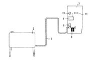
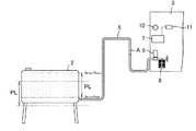
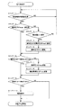
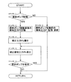
以下、本発明の一実施形態である給油装置について図面を参照しながら詳細に説明する。図1は、本実施形態の給油装置を示す概念図である。図2は、図1に示す給油装置がエア咬みを起こしている状態を示す概念図である。図3は、図1に示す給油装置の動作を示すフローチャートである。 Hereinafter, an oil supply apparatus according to an embodiment of the present invention will be described in detail with reference to the drawings. FIG. 1 is a conceptual diagram showing a fueling device of the present embodiment. FIG. 2 is a conceptual diagram showing a state in which the oil supply apparatus shown in FIG. FIG. 3 is a flowchart showing the operation of the fueling apparatus shown in FIG.
図1において、1は、本実施形態の給油装置である。給油装置1は、液体燃料を貯留する燃料タンク2と、液体燃料の供給を受ける機器3とを繋ぐ給油配管5の中途に圧力センサ6を設けた構成とされており、制御手段7(残量検知手段)によって残油量Qを求めるものである。圧力センサ6は、燃料タンク2に貯留されている液体燃料の位置水頭に基づいて発生する圧力を検知するものである。また、制御手段7は、圧力センサ6によって検知された検知圧力Pに基づいて燃料タンク2における残油量Qを導出する。制御手段7は、文字や画像を表示可能な表示装置やスピーカーのような音声発生装置からなる報知手段10を介して残油量Qや給油の要否を警告音や画面表示等の手法により報知する報知動作を行う。
In FIG. 1, reference numeral 1 denotes an oil supply apparatus according to this embodiment. The fueling device 1 is configured such that a
制御手段7は、燃料タンク2を液体燃料で満杯とした状態における検知圧力P(満杯圧力Pmax)に基づいて導出される残油量Qを満杯基準残量Qmaxとして認識する。また、制御手段7は、設定手段11を介して報知レベルパラメータLを設定することにより、報知レベル圧力PLを設定することができる。報知レベルパラメータLは、残油量Qが満杯基準残量Qmaxである際の液体燃料の液面位置と、報知基準残量Qminである際の液面位置との差を示す指標である。報知レベル圧力PLは、残油量Qが満杯基準残量Qmaxである際の位置水頭と、残油量Qが報知動作を行うべき量(報知基準残量Qmin)である際の位置水頭との差に相当するものである。制御手段7は、報知レベルパラメータLの設定値に応じて報知基準残量Qminに相当する検知圧力P(報知圧力Pmin)を記憶する。即ち、制御手段7は、満杯圧力Pmaxから報知レベル圧力PLを差し引いた(Pmax−PL)を報知圧力Pminとして認識する。
The control means 7 recognizes the remaining oil amount Q derived based on the detected pressure P (full pressure Pmax) when the
制御手段7は、必要に応じて満杯基準残量Qmaxおよび報知基準残量Qminに相当する満杯圧力Pmax、報知圧力Pminの更新を行う。さらに具体的に説明すると、給油装置1は、給油配管5の中途に空気等の気体が残存してしまう、いわゆるエア咬みの状態となることがある。例えば、図2に示すように給油配管5の中途に空気層Aが咬み込んでいる状態では、圧力センサ6によって検知される検知圧力Pが、実際の圧力よりも空気層Aに相当する位置水頭分だけ低く検知されてしまう。即ち、給油配管5がエア咬み状態にある場合、圧力センサ6により検知される検知圧力Pは、燃料タンク2における残油量Qに対して本来検知されるべき検知圧力Prよりも空気層Aの位置水頭に相当する圧力Pa分だけ低く検知されている。要するに、エア咬み状態で検知される検知圧力Pは、P=Pr−Paの関係にある。
The control means 7 updates the full pressure Pmax and the notification pressure Pmin corresponding to the full reference remaining amount Qmax and the notification reference remaining amount Qmin as necessary. More specifically, the fuel supply device 1 may be in a so-called air biting state in which a gas such as air remains in the middle of the
給油配管5がエア咬み状態のまま維持されている場合、圧力センサ6の検知圧力Pは、燃料タンク2が満杯状態の際の満杯圧力Pmax以下に維持されるはずである。しかし、燃料タンク2への液体燃料の補充や、機器3への液体燃料の供給を継続するうちに空気層Aが液体燃料に溶け込むなどして給油配管5から除去されると、同一の残油量Qに対する圧力センサ6の検知圧力Pは、エア咬み状態で検知されていたものよりも空気層Aの位置水頭に相当する圧力Pa分だけ増加する。即ち、エア咬み状態が解除されると、圧力センサ6の検知圧力Pは、本来検知されるべき検知圧力Prと等しくなる。そのため、エア咬み状態で設定された満杯圧力Pmax(以下、必要に応じてエア咬み満杯圧力Pb1と称す)は、エア咬み状態が解消された状態で燃料タンク2が満杯の時に本来検知されるべき満杯圧力Pmax(以下、必要に応じて実満杯圧力Pf1と称す)よりも空気層Aの位置水頭に相当する圧力Pa分だけ低くなる。即ち、エア咬み満杯圧力Pb1および実満杯圧力Pf1は、Pb1=Pf1−Paの関係にある。
When the
同様に、エア咬み状態で設定された報知圧力Pmin(以下、必要に応じてエア咬み報知基準圧力Pb2と称す)は、燃料タンク2内の残油量Qが報知動作を行うべき量となった時に本来検知されるべき報知圧力Pmin(以下、必要に応じて実報知基準圧力Pf2と称す)よりも空気層Aの位置水頭に相当する圧力Pa分だけ低い。即ち、エア咬み報知基準圧力Pb2および実報知基準圧力Pf2は、Pb2=Pf2−Paの関係にある。従って、残油量Qの判断基準となる満杯圧力Pmaxや報知圧力Pminは、エア咬みの解消にともなって圧力Pa分だけシフトする。
Similarly, the notification pressure Pmin set in the air biting state (hereinafter referred to as air biting notification reference pressure Pb2 if necessary) is the amount that the remaining oil amount Q in the
エア咬み状態が解消された状態において、エア咬み報知基準圧力Pb2は、本来報知動作を行うべき残油量Qに相当する検知圧力Pよりも低く、場合によっては燃料タンク2が空になった状態よりも低い位置に液体燃料が貯留されている場合の位置水頭に相当する圧力Paとなってしまう。即ち、エア咬み状態が解消される前に設定された満杯圧力Pmaxおよび報知圧力Pminに基づいて残油量Qの検知を行うと、報知基準残量Qminよりも空気層Aに相当する分だけ残油量Qが減少してから報知動作を行うこととなり、場合によっては燃料タンク2が空になっても報知動作が行われない可能性がある。
In the state where the air biting state has been eliminated, the air biting notification reference pressure Pb2 is lower than the detection pressure P corresponding to the residual oil amount Q that should be subjected to the notification operation, and in some cases the
そこで、本実施形態の給油装置1は、エア咬みの解消を検知することを条件として満杯圧力Pmaxおよび報知圧力Pminを更新する。さらに具体的に説明すると、給油装置1では、給油配管5に含まれている空気層Aが除去されると、燃料タンク2内に貯留されている液体燃料の液面位置が急激に変化し、これに連動して検知圧力Pが大きく変動する。即ち、エア咬みが解消すると、検知圧力Pおよびこれに基づいて検知される残油量Qが大きな変化率で変動する。また、燃料タンク2に液体燃料を補充した際の検知圧力Pが、先に設定されている満杯圧力Pmaxを越えている場合は、満杯圧力Pmaxの設定時に燃料タンク2が満杯にされていない状態であった可能性もあるが、液体燃料の補充やそれ以前の動作に伴ってエア咬みが解消された可能性が高い。液体燃料を燃料タンク2に補充した際の検知圧力Pが先に設定されている満杯圧力Pmaxを越えている場合は、いずれの場合であっても、先に設定されている満杯圧力Pmaxはこの時点において不適当であり、満杯圧力Pmaxの更新を行う必要がある。そのため、本実施形態の給油装置1では、圧力センサ6によって検知される検知圧力Pが先に設定されている満杯圧力Pmaxを越える場合にエア咬み状態が解消されたものと判断し、満杯圧力Pmaxおよび報知圧力Pminの更新動作を行う。以下、これらの更新動作について、図3に示すフローチャートを参照しながら詳細に説明する。
Therefore, the fueling device 1 of the present embodiment updates the full pressure Pmax and the notification pressure Pmin on condition that the cancellation of the air bite is detected. More specifically, in the fuel supply device 1, when the air layer A contained in the
給油装置1が動作を開始すると、制御手段7は、まずステップ1−1において給油報知初期設定が完了しているか否かを確認する。さらに具体的には、制御手段7は、報知レベルパラメータLの設定がなされ、報知レベル圧力PLが認識されているかを確認する。ここで、報知レベルパラメータLが設定されていない場合、制御手段7は制御フローを戻して報知レベルパラメータLが設定されるのを待つ。 When the fueling device 1 starts operating, the control means 7 first checks in step 1-1 whether or not the fueling notification initial setting has been completed. More specifically, the control means 7 confirms whether the notification level parameter L is set and the notification level pressure PL is recognized. Here, when the notification level parameter L is not set, the control means 7 returns the control flow and waits for the notification level parameter L to be set.
一方、ステップ1−1において給油報知初期設定が完了していることが確認されると、制御フローがステップ1−2に進行する。制御手段7は、ステップ1−2において満杯圧力Pmaxの設定が完了しているかを確認する。ステップ1−2において、満杯圧力Pmaxの設定が完了していない場合、制御手段7は、ステップ1−3において燃料タンク2における液体燃料の残油量Qが満杯であるか否かを確認する。ここで、燃料タンク2が満杯状態でない場合、制御手段7は、制御フローをステップ1−1に戻し、燃料タンク2が満杯になるのを待つ。一方、ステップ1−3において燃料タンク2が液体燃料で満杯であることが確認されると、制御手段7は、制御フローをステップ1−4に進め、この時点で圧力センサ6によって検知されている検知圧力Pを満杯圧力Pmaxとして記憶する。即ち、制御手段7は、燃料タンク2が液体燃料で満杯になったタイミングで満杯圧力Pmaxを設定する。その後、ステップ1−5において、制御手段7は、ステップ1−4において設定された満杯圧力Pmaxから報知レベルパラメータLに相当する報知レベル圧力PLを差し引いた(Pmax−PL)を報知圧力Pminとして記憶する。
On the other hand, when it is confirmed in step 1-1 that the refueling notification initial setting is completed, the control flow proceeds to step 1-2. The control means 7 confirms whether or not the full pressure Pmax has been set in step 1-2. If the full pressure Pmax has not been set in step 1-2, the control means 7 confirms in step 1-3 whether or not the remaining amount Q of liquid fuel in the
ステップ1−2およびステップ1−5が完了すると、制御フローはステップ1−6へと進行する。制御手段7は、ステップ1−6において圧力センサ6の検知圧力Pが満杯圧力Pmax以下であるかを確認する。ここで検知圧力Pが満杯圧力Pmaxを越えている場合は、先に設定されている満杯圧力Pmaxが、燃料タンク2が液体燃料で満杯状態となった場合の位置水頭を反映したものではなく、エア咬み時に給油配管5内にある空気層Aの分に相当する圧力Paだけ低く設定されたものであると考えられる。そこで、制御手段7は、検知圧力Pが満杯圧力Pmaxを越えることを条件として制御フローをステップ1−7に進め、予め記憶されていた満杯圧力Pmaxをこの時点で検知されている検知圧力Pによって更新する。その後、ステップ1−7において更新された満杯圧力Pmaxから報知レベル圧力PLを差し引いた(Pmax−PL)が報知圧力Pminとして更新され記憶される。(ステップ1−8)
When step 1-2 and step 1-5 are completed, the control flow proceeds to step 1-6. In step 1-6, the control means 7 confirms whether the detected pressure P of the
ステップ1−6において検知圧力Pが満杯圧力Pmax以下である場合や、ステップ1−7およびステップ1−8において満杯圧力Pmaxや報知圧力Pminの更新が行われると、制御フローはステップ1−9に進行する。制御手段7は、ステップ1−9において圧力センサ6で検知されている検知圧力Pを確認する。ここで確認された検知圧力Pが報知圧力Pmin未満になっている場合、制御手段7は、ステップ1−10において例えば図示しない報知手段を介して警告音を発したり、画面表示するなどして報知動作を行う。
If the detected pressure P is less than or equal to the full pressure Pmax in step 1-6, or if the full pressure Pmax or the notification pressure Pmin is updated in steps 1-7 and 1-8, the control flow goes to step 1-9. proceed. The control means 7 confirms the detected pressure P detected by the
上記したように、本実施形態の給油装置1では、燃料タンク2と機器3とを繋ぐ給油配管5においていわゆるエア咬みが発生した場合であっても、エア咬みの解消前後における液体燃料の残油量Qの検知精度が低下しない。そのため、本実施形態の給油装置1によれば、液体燃料の残油量Qや、残油量Qが所定の報知基準残量Qminに達したことを正確に検知し、報知することができる。
As described above, in the fuel supply device 1 according to the present embodiment, even when a so-called air bite occurs in the
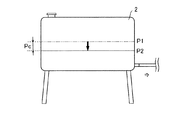
上記した給油装置1では、給油配管5の中途に液体燃料を圧送するための燃料ポンプ8が設置されている。そのため、機器3に向けて液体燃料を圧送する場合は、圧力センサ6の検知圧力Pが燃料ポンプ8の影響を受けて変動するおそれがある。さらに具体的には、上記実施形態では、図4に示すように、実際の液体燃料の残油量Qを反映した検知圧力P、即ち燃料ポンプ8の停止時の検知圧力PがP1である場合、燃料ポンプ8の動作に伴って圧力Pc(以下、必要に応じて補正圧力Pcと称す)分だけ低下し、燃料ポンプ8の動作時の検知圧力がP2となる(P1=Pc+P2)。そのため、制御手段7によって残油量Qを検知する場合は、燃料ポンプ8の動作状況に合わせて検知圧力Pの補正を行うことが望ましい。
In the fueling device 1 described above, a
さらに詳細に説明すると、燃料ポンプ8の動作に伴う検知圧力Pの変動が見込まれる場合は、上記した制御フローのステップ1−4,5,7の動作において判断基準として採用されている検知圧力Pの代わりに、これを補正圧力Pcによって補正した補正検知圧力Ph(Ph=P±Pc)を採用する。これにより、上記した制御フローによる残量検知動作および報知動作が、燃料ポンプ8の動作に伴う圧力変動が加味され、より一層信頼性が向上する。
More specifically, when the fluctuation of the detected pressure P due to the operation of the
上記した補正圧力Pcは、燃料ポンプ8の吸引能力や圧送能力に大きく依存するが、給油配管5の長さや折り曲げの程度等のような設置状態にも大きく依存している。そのため、補正圧力Pcは、燃料ポンプ8の能力のみを考慮して適宜調整されてもよいが、給油配管5の長さや折り曲げの程度等のような給油装置1の設置状態に起因して発生する圧力変動を加味して調整されることが望ましい。さらに具体的には、補正圧力Pcは、例えば燃料タンク2が空になる前後のように所定のタイミングにおける検知圧力Pの変動を検知することにより導出することができる。即ち、補正圧力Pcを設定する場合、燃料ポンプ8の動作前の検知圧力をP1とし、燃料ポンプ8の動作開始直後の検知圧力PをP2とすると、補正圧力Pcは、Pc=|P1−P2|となる。補正圧力Pcは、燃料ポンプ8の能力や、給油装置1の設置状態を加味したものであり、液体燃料を機器3に供給する際の圧力変動を反映したものである。そのため、燃料ポンプ8が動作する場合は、上記した制御フローのステップ1−4,5,7において採用されている検知圧力Pの代わりに、検知圧力Pを補正圧力Pcによって補正した補正検知圧力Ph(Ph=P±Pc)を採用することが望ましい。
The correction pressure Pc described above largely depends on the suction capability and the pumping capability of the
さらに具体的に説明すると、燃料ポンプ8の動作状態に応じて検知圧力Pを補正圧力Pcで補正する場合、制御手段7は、図5に示す制御フローのように、ステップ2−1において燃料ポンプ8が動作を開始したか否かを確認する。ここで、燃料ポンプ8が停止したままである場合、制御手段7は、制御フローをステップ2−2に進め、この時点で検知されている検知圧力P1を記憶し、制御フローをステップ2−1に戻す。
More specifically, when the detected pressure P is corrected with the correction pressure Pc according to the operating state of the
一方、ステップ2−1において燃料ポンプ8の起動が確認されると、制御手段7は、ステップ2−3において燃料ポンプ8の起動直後に圧力センサ6によって検知された検知圧力P2を記憶する。その後、制御手段7は、ステップ2−4において燃料ポンプ8の起動前に検知された検知圧力P1とステップ2−3で検知された検知圧力P2の差を求めることにより補正圧力Pc(Pc=|P1−P2|)を導出する。その後、制御手段7は、ステップ2−3で導出された補正圧力Pcにより、実際に圧力センサ6に検知されている圧力Pを補正した補正検知圧力Ph(Ph=P±Pc)を導出する(ステップ2−5)。
On the other hand, when the start of the
制御手段7は、ステップ2−6において燃料ポンプ8が作動中である間は、上記したステップ1−1から1−10に至る一連の制御フローにおいて判断の対象を検知圧力Pから補正検知圧力Phに変更し、一連の制御フローを継続する。一方、ステップ2−6において燃料ポンプ8が停止したことが確認されると、制御手段7は、補正検知圧力Phの導出を停止し、制御フローをステップ2−1に戻す。これに伴い、燃料ポンプ8の停止中は、ステップ1−1から1−10に至る一連の制御フローにおける判断の対象が検知圧力Pに戻される。
While the
上記したステップ2−1からステップ2−6に至る一連のフローによれば、燃料ポンプ8の動作の有無による補正圧力Pの変動を加味することができ、ステップ1−1から1−10に至る一連の制御フローによる残油量Qの検知精度をより一層向上することができる。
According to the series of flow from step 2-1 to step 2-6 described above, the fluctuation of the correction pressure P due to the presence or absence of operation of the
また、図5に示す制御フローでは、ステップ2−2において燃料ポンプ8の停止時に検知される検知圧力P1を燃料ポンプ8が起動、即ち機器3側への燃料の供給が開始されるまで適宜更新し記憶するものであったが、ここで更新される検知圧力P1が燃料の供給が停止しているにもかかわらず低下している場合は液体燃料が漏洩している可能性がある。そのため、図5に示す制御フローにおいて、ステップ2−2の後に検知圧力P1の変動を確認することにより、燃料の漏洩を検知し、これに伴う不具合の発生を未然に防止することができる。
In the control flow shown in FIG. 5, the detected pressure P1 detected when the
上記したように、図3に示す制御フローは、ステップ1−1からステップ1−5に至る一連のフローにおいて燃料タンク2が液体燃料によって満杯状態である場合の検知圧力に基づいて報知動作の基準となる報知基準圧力Pminを設定するものであったが、本発明はこれに限定されるものではなく、例えば燃料タンク2から機器3側に供給されるべきである液体燃料が供給されない場合、即ち燃料タンク2が空であると想定される場合に検知される検知圧力P(基準圧力)に基づいて報知基準圧力Pminを設定することも可能である。即ち、給油装置1の設置直後のように燃料タンク2内に液体燃料が入っていない場合や、給油装置1による液体燃料の供給に伴い燃料タンク2を空にしてしまった場合に圧力センサ6によって検知される検知圧力Pに基づいて報知基準圧力Pminを設定することも可能である。
As described above, the control flow shown in FIG. 3 is based on the detected pressure when the
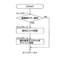
さらに具体的には、図3に示す制御フローのステップ1−1からステップ1−5に至る制御フローに代わって図6に示す制御フローにより報知基準圧力Pminの設定を行ってもよい。図6の制御フローにより報知基準圧力Pminの設定を行う場合、制御手段7は先ずステップ3−1において機器3側から燃料供給停止に伴うエラー信号が発信されていないかを確認する。ステップ3−1において機器3側からエラー信号が発信されていない場合、制御手段7は、制御フローを上記したステップ1−6に進める。一方、ステップ3−1において機器3側からエラー信号が発信されている場合は、制御フローがステップ3−2に進行し、制御手段7がこの時点で検知されている検知圧力P3(基準圧力)を燃料タンク2が空の際の圧力として記憶する。
More specifically, the notification reference pressure Pmin may be set by the control flow shown in FIG. 6 instead of the control flow from step 1-1 to step 1-5 of the control flow shown in FIG. When the notification reference pressure Pmin is set according to the control flow of FIG. 6, the control means 7 first confirms in step 3-1 whether or not an error signal accompanying the stop of fuel supply is transmitted from the
ステップ3−2において検知圧力P3が記憶されると、制御手段7は、ステップ3−3において検知圧力P3よりも所定の補正値αだけ高い圧力(P3+α)を報知基準圧力Pminとして記憶する。その後、制御手段7は、制御フローを図3に示すステップ1−6に進め、残油量Qの検知を行う。そのため、制御手段7は、燃料タンク2が空の状態よりも位置水頭αに相当する分だけ高い位置に液体燃料の液面位置が到達すると報知動作を行う。
When the detected pressure P3 is stored in step 3-2, the control means 7 stores a pressure (P3 + α) that is higher than the detected pressure P3 by a predetermined correction value α as the notification reference pressure Pmin in step 3-3. Thereafter, the control means 7 advances the control flow to step 1-6 shown in FIG. For this reason, the control means 7 performs a notification operation when the liquid fuel level reaches a position higher than the empty state of the
上記したように、図6に示す制御フローによれば報知基準圧力Pminを正確に設定することができ、燃料タンク2が空になる前に的確に報知動作を行うことができる。なお、上記したステップ3−3において報知基準圧力Pminの設定の際に採用される補正値αは、予め設定された設定値であっても、操作者が適宜設定するものであってもよい。
As described above, according to the control flow shown in FIG. 6, the notification reference pressure Pmin can be set accurately, and the notification operation can be performed accurately before the
また、上記したステップ3−1〜3−3に至る制御フローにおいて設定される報知基準圧力Pminについても燃料ポンプ8の動作による液体燃料の脈動等の影響を受け、報知動作に悪影響を及ぼすおそれがある。そのため、このような事態が懸念される場合は、上記したステップ2−4と同様にして燃料ポンプ8の起動前後における検知圧力Pの差に相当する補正圧力Pcを導出し、この補正圧力Pcにより報知基準圧力Pminを補正することが好ましい。即ち、燃料ポンプ8の動作による影響を考慮する場合は、報知基準圧力Pminを(P3+α±Pc)とすることが望ましい。
Further, the notification reference pressure Pmin set in the control flow up to the above steps 3-1 to 3-3 is also affected by the pulsation of the liquid fuel caused by the operation of the
図6に示す制御フローは、エラー信号を受信した時点で検知された検知圧力P3(基準圧力)を基準として報知基準圧力Pminを設定するものであったが、エラー信号を検知した直後は燃料ポンプ8等の動作の影響を受け、検知圧力Pが不安定であるおそれがある。そこで、かかる懸念を払拭すべく、報知基準圧力Pminの設定時には検知圧力P3の検知のタイミングをエラー信号を受信した時点からある程度の時間が経過した後にすることが望ましい。 In the control flow shown in FIG. 6, the notification reference pressure Pmin is set based on the detected pressure P3 (reference pressure) detected when the error signal is received, but immediately after the error signal is detected, the fuel pump. The detection pressure P may be unstable due to the influence of the operation of No. 8 or the like. Therefore, in order to eliminate such a concern, it is desirable that the detection pressure P3 is detected after a certain amount of time has elapsed from the time when the error signal is received when the notification reference pressure Pmin is set.
また、図6に示す制御フローでは、エラー信号を受信した際の検知圧力P3を補正値αによって補正した(P3+α)を報知基準圧力Pminとしたが、本発明はこれに限定されるものではなく、例えばエラー信号を受信する時点よりも所定時間Y以上前に検知された検知圧力P4を報知基準圧力Pminとしてもよい。即ち、報知基準圧力Pminは、(P3+α)に代わって検知圧力P4とすることも可能である。 In the control flow shown in FIG. 6, (P3 + α) obtained by correcting the detected pressure P3 when the error signal is received by the correction value α is set as the notification reference pressure Pmin, but the present invention is not limited to this. For example, the detected pressure P4 detected a predetermined time Y or more before the time when the error signal is received may be used as the notification reference pressure Pmin. That is, the notification reference pressure Pmin can be set to the detected pressure P4 instead of (P3 + α).
また、検知圧力P4を検知するタイミングは、エラー信号を受信した時点から所定時間Y前に検知された検知圧力Pであってもよいが、液体燃料を機器3に向けて供給している間は燃料ポンプ8の動作等の影響を受けて検知圧力Pが不安定であるおそれがある。そのため、検知圧力P4を持って報知基準圧力Pminを設定する場合は、所定時間Y以上前の時点であって、機器3への液体燃料の供給停止時に検知された圧力とすることがより一層好ましい。
In addition, the detection pressure P4 may be detected at the detection pressure P detected a predetermined time Y from the time when the error signal is received, but while the liquid fuel is being supplied toward the
図6に示す制御フローでは、機器3側から発信されるエラー信号を受信した際に検知される検知圧力P3に基づいて報知基準圧力Pminを設定するものであるため、報知基準圧力Pminは燃料タンク2が実質的に空である状態を基準とするものであるが、燃料タンク2内における残油量Qが所定量である場合を基準に設定されるものであってもよい。さらに具体的には、図6に示す制御フローでは、ステップ3−1において機器3側から発信されるエラー信号をトリガーとして検知圧力P3を検知するものであったが、これに代わって例えば圧力センサ6によって検知される検知圧力Pが所定の変化率以上で増加したことを条件として燃料タンク2への燃料の補給動作が行われたものと判断し、この補給動作の直前に検知された検知圧力Pを上記した検知圧力P3とすることも可能である。かかる構成によれば、燃料タンク2が空あるいは所定量以下になったことを的確に検知し、報知基準圧力Pminの設定の基準となる検知圧力P3を適正値に設定することができる。
In the control flow shown in FIG. 6, the notification reference pressure Pmin is set based on the detected pressure P3 detected when an error signal transmitted from the
上記したように、図6に示す制御フローでは機器3側からエラー信号が発信された後に検知圧力P3を検知するものであったが、エラー信号が発信された後に図示しないリモコン等の入力手段を介して操作者に燃料タンク2が空であることを確認した旨の確認信号を発信させる構成とし、エラー信号と確認信号とが検知された時点で検知圧力P3を検出する構成としてもよい。
As described above, in the control flow shown in FIG. 6, the detection pressure P3 is detected after an error signal is transmitted from the
上記実施形態において、制御手段7は、図3に示す制御フローのステップ3のように、燃料タンク2が液体燃料で満杯であることを条件としてその時の検知圧力Pを満杯圧力Pmaxとして設定するものであったが、本発明はこれに限定されるものではない。さらに具体的には、例えば圧力センサ6により検知される検知圧力Pの変化率を検知し、この変化率が所定値よりも大きい時に液体燃料の補充(補充動作)が行われたものと判断し、この補充動作後に検知される検知圧力P(補充後検知圧力Px)によって満杯圧力Pmaxが設定されるものであってもよい。
In the above embodiment, the control means 7 sets the detected pressure P at that time as the full pressure Pmax on condition that the
また、上記実施形態では、図3に示す制御フローのステップ1−6〜8に示すように検知圧力Pが満杯圧力Pmaxを越えた際に満杯圧力Pmaxおよび報知圧力Pminを更新するものであったが、本発明はこれに限定されるものではない。さらに具体的には、例えば上記した補充動作後に検知される補充後検知圧力Pxと先に設定されている満杯圧力Pmaxとを比較し、補充後検知圧力Pxが満杯圧力Pmaxを越える場合に、満杯圧力Pmaxをこの補充後検知圧力Pxによって更新する構成とすることも可能である。かかる構成によっても、エア咬みの解消に伴う満杯圧力Pmaxや報知圧力Pminのズレを適切に補正することができ、液体燃料の残量を正確に検知できる。 In the above embodiment, the full pressure Pmax and the notification pressure Pmin are updated when the detected pressure P exceeds the full pressure Pmax as shown in steps 1-6 to 8 of the control flow shown in FIG. However, the present invention is not limited to this. More specifically, for example, when the post-replenishment detection pressure Px detected after the above-mentioned replenishment operation is compared with the previously set full pressure Pmax, and the post-replenishment detection pressure Px exceeds the full pressure Pmax, the full pressure is reached. It is also possible to update the pressure Pmax with the post-replenishment detection pressure Px. Even with such a configuration, it is possible to appropriately correct the deviation of the full pressure Pmax and the notification pressure Pmin associated with the elimination of the air bite, and it is possible to accurately detect the remaining amount of liquid fuel.
上記実施形態の給油装置1は、報知レベルパラメータLの設定により報知圧力Pminおよび報知基準残量Qminが設定されるものであったが、本発明はこれに限定されるものではない。さらに具体的には、例えば上記したように圧力センサ6により検知される検知圧力Pの変化率を検知するなどして補充動作がなされたことを検知し、この補充動作の直前に検知された検知圧力(補充前検知圧力Py)を記憶しておき、補充動作が複数回行われた際に補充前検知圧力Pyの変動履歴を考慮して報知圧力Pminや報知基準残量Qminの補正あるいは設定を行ってもよい。かかる構成によれば、報知動作を行う際の報知圧力Pminおよび報知基準残量Qminをより一層最適化し、液体燃料の補給を行うのに最適な時期に報知動作を行うことができる。なお、補充前検知圧力Pyの変動履歴は、過去数回分の補充前検知圧力Pyを平均したり、過去に検知された補充前検知圧力Pyのうち最も低いものを採用する等の手法により判断することができる。
In the fueling device 1 of the above embodiment, the notification pressure Pmin and the notification reference remaining amount Qmin are set by setting the notification level parameter L, but the present invention is not limited to this. More specifically, for example, it is detected that the replenishment operation has been performed by detecting the rate of change of the detected pressure P detected by the
本実施形態では、燃料タンク2が液体燃料によって満杯状態となった状態における検知圧力Pを満杯圧力Pmaxと設定し、これに基づいて報知圧力Pmin等のパラメータを設定するものであったが、満杯圧力Pmaxに代わって例えば液体燃料の残油量Qが所定量貯留されている場合の検知圧力Pを基準とし、報知圧力Pmin等のパラメータを設定してもよい。
In the present embodiment, the detection pressure P in the state where the
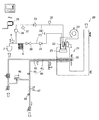
以下、上記実施形態において説明した給油装置1を採用した熱源装置について図面を参照しながら詳細に説明する。図7において、20は本実施例の燃焼装置である。熱源装置20は、上記実施形態に示した給油装置1を備えている。燃焼部21は、液体燃料を噴霧する燃料噴霧ノズル22と、送風機23によって外気が導入され、燃料噴霧ノズル22において噴霧された燃料を燃焼する燃焼筒25とを有する。燃焼筒25の下流側には、燃焼部21における液体燃料の燃焼に伴って発生する高温の燃焼ガスとの熱交換により湯水を加熱する熱交換器26が配置されている。
Hereinafter, a heat source device that employs the oil supply device 1 described in the above embodiment will be described in detail with reference to the drawings. In FIG. 7, 20 is a combustion apparatus of the present embodiment. The
燃料噴霧ノズル22は、燃料を噴霧するための噴霧開口(図示せず)を有する。燃料噴霧ノズル22は、内部に噴霧開口に至る燃料往路(図示せず)と燃料復路(図示せず)とを具備した、いわゆる戻り型ノズル(リターン型ノズル)である。即ち、燃料噴霧ノズル22は、燃料往路を介して燃料噴霧ノズル22の外部から供給された燃料を噴霧開口から噴霧し、噴霧されずに残った燃料を燃料復路を通じて排出する構成を有する。
The
燃料噴霧ノズル22は、図7に示すように給油配管5を介して燃料が貯留されている燃料タンク2に接続されている。給油配管5は、大別して前記した燃料噴霧ノズル22の燃料往路と連通する燃料往路27と、燃料噴霧ノズル22の燃料復路と連通する燃料復路28とにより構成されている。
The
燃料往路27は、燃料タンク2内に貯留されている燃料を燃料噴霧ノズル22に供給するための流路である。燃料往路27は、燃料タンク2と燃料噴霧ノズル22とを直列的に接続したものである。燃料往路27の中途には、圧力センサ6(圧力検知手段)、燃料ポンプ8、電磁弁30、並びに、逆止弁31が燃料タンク2側から順次接続されている。圧力センサ6は、燃料往路27の中途に設置され、燃料往路27内の液体燃料の圧力を検知するものであり、この検知データは熱源装置20の作動制御を行う制御装置35に向けて発信される。
The
燃料復路28は、燃料噴霧ノズル22において噴霧されずに残った燃料を燃料タンク2側に戻すものである。燃料復路28の下流端側は、燃料往路27の中途であって、圧力センサ6と燃料ポンプ8との中途に接続されている。燃料復路28の中途には、燃料復路28内を流れる燃料の温度を検知する温度センサ32(温度検知手段)が設けられている。温度センサ32の下流側には、燃料噴霧ノズル22側から燃料タンク2側へ燃料を流し、燃料の逆流を阻止する逆止弁33が設けられている。逆止弁33の下流側には、燃料タンク2側への燃料の戻り量を調整する流量調整弁36が設けられている。また、流量調整弁36と逆止弁33との間には、燃料復路28内を流れる燃料の圧力を緩衝すべく、アキュムレータ37が設けられている。
The
熱交換器26には、流水回路40が接続されている。流水回路40は、給湯栓などに接続され外部に湯水を流出する、いわゆる給湯回路である。流水回路40は、熱交換器26に外部から水を給水する給水流路41と、熱交換器26において加熱された湯水が流れる給湯流路43と、給水流路41から分岐されたバイパス流路45とを有する。流水回路40は、バイパス流路45を流れる冷水のバイパス水量と給湯流路43内を流れる高温の湯水の量とをバイパス水量調節弁46によって調節し、これらの湯水を混合して温度調節された湯水を外部に供給する。
A flowing
給湯流路43とバイパス流路45との混合部分の下流側には、水量調節弁47と出湯センサ48とが設けられている。出湯センサ48によって検知された温度が前記したバイパス水量調節弁46等にフィードバックされると共に、水量調節弁47によって総水量が調節される。給水流路41には、出湯センサ50と、水温センサ51が設けられている。後述する制御装置35は、出湯センサ50および水温センサ51の検知信号に基づき、高温湯の温度が80℃程度となるように燃焼部21の燃焼量を調節する。
A water
本実施形態の熱源装置20は、燃焼部21の燃焼量や流水回路40内を流れる湯水の流量調整等を管理し、制御する制御装置35を具備している。制御装置35は、CPUを中心として構成されるものであり、RAM、ROM、I/Oポート、および、アナログのセンサ信号をデジタル信号に変換するA/D変換回路、あるいは、生成されたデジタル制御信号をアナログ制御信号に変換するD/A変換回路などを備えている。制御装置35には、上記実施形態に示した給油装置1の制御手段7が組み込まれている。制御装置35は、制御に用いる各種の判別基準値を予めROMに格納しており、CPUで上記した各検知手段の検知信号を随時参照し、所定のプログラムに従って処理を行う。
The
熱源装置20は、制御装置35に組み込まれた給油装置1の制御手段7により残油量Qの検知を行う。熱源装置20は、残油量Qが報知基準残量Qmin以下となり、圧力センサ6による検知圧力Pが報知圧力Pmin以下となると液体燃料の補充を促す報知動作を行う。熱源装置20は、給湯温度の設定等のような熱源装置20の操作を行うために設置されたリモコン55のスピーカー56(音声発信手段)により警告音や音声を発信させたり、表示部56を介して画面表示を行う等の手法で行われる。
The
本実施例の熱源装置20は、上記実施形態に示した給油装置1を備えているため、給油配管5におけるエア咬みの有無にかかわらず燃料タンク2における残油量Qの検知や、燃料タンク2への液体燃料の補充を促す報知動作を的確に行える。
Since the
なお、上記実施形態においては、残油量Qが報知基準残量Qmin以下となり、圧力センサ6による検知圧力Pが報知圧力Pmin以下となった際にスピーカー56や表示部56を介して報知動作を行うものであったが、本発明はこれに限定されるものではなく、例えば表示部56に液体燃料の供給業者の連絡先を表示したり、図示しない通信手段を介して供給業者に対して液体燃料の補給を行うように連絡が入る構成とすることも可能である。かかる構成によれば、残油量Qが報知基準残量Qmin以下となったことを操作者に対して的確に報知できると共に、液体燃料の補給時に操作者にかかる手間を解消することができる。
In the above embodiment, when the residual oil amount Q is equal to or less than the notification reference remaining amount Qmin and the detected pressure P detected by the
本実施例の熱源装置20は、本発明の給油装置の一使用形態を示したものに過ぎず、液体燃料の供給を受けて動作する他の形態の熱源装置や給湯装置、燃焼装置等の機器類にも好適に使用できる。
The
1 給油装置
2 燃料タンク
5 給油配管
6 圧力センサ(圧力検知手段)
7 制御手段(残量検知手段)
8 燃料ポンプ
DESCRIPTION OF SYMBOLS 1
7 Control means (remaining amount detection means)
8 Fuel pump
Claims (10)
前記残量検知手段は、燃料貯留手段が空あるいは液体燃料の残量が所定量以下であると想定される場合に圧力検知手段によって検知される検知圧力を基準圧力として検出し、当該基準圧力よりも所定の補正圧力だけ高い圧力を報知基準圧力と認識することを特徴とする給油装置。 Fuel storage means for storing liquid fuel, pressure detection means for detecting pressure based on the liquid fuel stored in the fuel storage means, and storage in the fuel storage means based on the pressure detected by the pressure detection means A remaining amount detecting means for detecting the remaining amount of the liquid fuel, and a notifying means for performing a notification operation on condition that the detected pressure detected by the pressure detecting means is equal to or lower than a predetermined notification reference pressure. ,
The remaining amount detecting means detects, as a reference pressure, a detected pressure detected by the pressure detecting means when the fuel storing means is empty or the remaining amount of liquid fuel is assumed to be a predetermined amount or less. A refueling device that recognizes a pressure that is higher by a predetermined correction pressure as a notification reference pressure.
Priority Applications (1)
| Application Number | Priority Date | Filing Date | Title |
|---|---|---|---|
| JP2004108592A JP2005291636A (en) | 2004-03-31 | 2004-03-31 | Lubricating device |
Applications Claiming Priority (1)
| Application Number | Priority Date | Filing Date | Title |
|---|---|---|---|
| JP2004108592A JP2005291636A (en) | 2004-03-31 | 2004-03-31 | Lubricating device |
Publications (1)
| Publication Number | Publication Date |
|---|---|
| JP2005291636A true JP2005291636A (en) | 2005-10-20 |
Family
ID=35324755
Family Applications (1)
| Application Number | Title | Priority Date | Filing Date |
|---|---|---|---|
| JP2004108592A Pending JP2005291636A (en) | 2004-03-31 | 2004-03-31 | Lubricating device |
Country Status (1)
| Country | Link |
|---|---|
| JP (1) | JP2005291636A (en) |
Cited By (2)
| Publication number | Priority date | Publication date | Assignee | Title |
|---|---|---|---|---|
| CN103147890A (en) * | 2013-03-20 | 2013-06-12 | 勾昌羽 | Anti-explosion oil supply system for pneumatic oil tank |
| WO2016083348A1 (en) * | 2014-11-27 | 2016-06-02 | Caterpillar Sarl | Fuel supply apparatus in construction machine |
-
2004
- 2004-03-31 JP JP2004108592A patent/JP2005291636A/en active Pending
Cited By (3)
| Publication number | Priority date | Publication date | Assignee | Title |
|---|---|---|---|---|
| CN103147890A (en) * | 2013-03-20 | 2013-06-12 | 勾昌羽 | Anti-explosion oil supply system for pneumatic oil tank |
| WO2016083348A1 (en) * | 2014-11-27 | 2016-06-02 | Caterpillar Sarl | Fuel supply apparatus in construction machine |
| US10197024B2 (en) | 2014-11-27 | 2019-02-05 | Caterpillar Sarl | Fuel supply apparatus in construction machine |
Similar Documents
| Publication | Publication Date | Title |
|---|---|---|
| JP6327341B2 (en) | Fuel gas filling system and fuel gas filling method | |
| EP2313694B1 (en) | Method for controlling a hot water temperature in using low flux in hot water supply system | |
| CN102472176B (en) | Control device for internal combustion engine | |
| US9726400B2 (en) | Hot water supply device | |
| EP3112750A1 (en) | Method and device for controlling charging of chemical into boiler | |
| JP2005291636A (en) | Lubricating device | |
| JP2015214993A (en) | Fuel gas filling system and fuel gas filling method | |
| JP4274816B2 (en) | Power generation system, operation method thereof, and operation control device | |
| JP5442569B2 (en) | Bath water heater | |
| CN111928489A (en) | Self-adaptive method for temperature rise of gas water heater in circulating start-stop mode | |
| JP6323269B2 (en) | Boiler equipment | |
| JP7000875B2 (en) | Boiler system | |
| JP4171912B2 (en) | Combustion device | |
| JP4243849B2 (en) | Combustion equipment | |
| CN112503552B (en) | Fire detection sensor cleaning system, method and computer readable medium | |
| JP2009287838A (en) | Heat pump water heater | |
| GB2437175A (en) | Water heating system control | |
| JP5811332B2 (en) | Heat source machine | |
| JP2008133507A (en) | Method and device for controlling pressure of compressed air for controlling plating deposit | |
| KR100559250B1 (en) | Automatic water supply valve / oil sensor failure detection method and apparatus for gas boiler using heating water temperature | |
| JP7295712B2 (en) | fuel supply | |
| JP6380113B2 (en) | Boiler system | |
| JP4102725B2 (en) | Boiler to prevent frequent changes in combustion volume | |
| JP3754503B2 (en) | Bath and hot water supply equipment | |
| KR100951523B1 (en) | How to adjust steam flow rate through oil temperature control |
Legal Events
| Date | Code | Title | Description |
|---|---|---|---|
| A621 | Written request for application examination |
Free format text: JAPANESE INTERMEDIATE CODE: A621 Effective date: 20070323 |
|
| A977 | Report on retrieval |
Free format text: JAPANESE INTERMEDIATE CODE: A971007 Effective date: 20080704 |
|
| A131 | Notification of reasons for refusal |
Free format text: JAPANESE INTERMEDIATE CODE: A131 Effective date: 20080716 |
|
| A02 | Decision of refusal |
Effective date: 20081203 Free format text: JAPANESE INTERMEDIATE CODE: A02 |