JP2005291497A - Auxiliary latch/confirming mechanism for quick coupling - Google Patents

Auxiliary latch/confirming mechanism for quick coupling Download PDF

Info

Publication number
JP2005291497A
JP2005291497A JP2005100962A JP2005100962A JP2005291497A JP 2005291497 A JP2005291497 A JP 2005291497A JP 2005100962 A JP2005100962 A JP 2005100962A JP 2005100962 A JP2005100962 A JP 2005100962A JP 2005291497 A JP2005291497 A JP 2005291497A
Authority
JP
Japan
Prior art keywords
connector body
male member
retainer
quick coupling
latch
Prior art date
Legal status (The legal status is an assumption and is not a legal conclusion. Google has not performed a legal analysis and makes no representation as to the accuracy of the status listed.)
Granted
Application number
JP2005100962A
Other languages
Japanese (ja)
Other versions
JP2005291497A5 (en
JP5025091B2 (en
Inventor
Richard M Pepe
エム. ぺぺ リチャード
Jim Kerin
ケリン ジム
Current Assignee (The listed assignees may be inaccurate. Google has not performed a legal analysis and makes no representation or warranty as to the accuracy of the list.)
TI Group Automotive Systems LLC
Original Assignee
TI Group Automotive Systems LLC
Priority date (The priority date is an assumption and is not a legal conclusion. Google has not performed a legal analysis and makes no representation as to the accuracy of the date listed.)
Filing date
Publication date
Application filed by TI Group Automotive Systems LLC filed Critical TI Group Automotive Systems LLC
Publication of JP2005291497A publication Critical patent/JP2005291497A/en
Publication of JP2005291497A5 publication Critical patent/JP2005291497A5/ja
Application granted granted Critical
Publication of JP5025091B2 publication Critical patent/JP5025091B2/en
Anticipated expiration legal-status Critical
Expired - Fee Related legal-status Critical Current

Links

Images

Classifications

    • HELECTRICITY
    • H01ELECTRIC ELEMENTS
    • H01RELECTRICALLY-CONDUCTIVE CONNECTIONS; STRUCTURAL ASSOCIATIONS OF A PLURALITY OF MUTUALLY-INSULATED ELECTRICAL CONNECTING ELEMENTS; COUPLING DEVICES; CURRENT COLLECTORS
    • H01R13/00Details of coupling devices of the kinds covered by groups H01R12/70 or H01R24/00 - H01R33/00
    • H01R13/62Means for facilitating engagement or disengagement of coupling parts or for holding them in engagement
    • H01R13/639Additional means for holding or locking coupling parts together, after engagement, e.g. separate keylock, retainer strap
    • FMECHANICAL ENGINEERING; LIGHTING; HEATING; WEAPONS; BLASTING
    • F16ENGINEERING ELEMENTS AND UNITS; GENERAL MEASURES FOR PRODUCING AND MAINTAINING EFFECTIVE FUNCTIONING OF MACHINES OR INSTALLATIONS; THERMAL INSULATION IN GENERAL
    • F16LPIPES; JOINTS OR FITTINGS FOR PIPES; SUPPORTS FOR PIPES, CABLES OR PROTECTIVE TUBING; MEANS FOR THERMAL INSULATION IN GENERAL
    • F16L37/00Couplings of the quick-acting type
    • F16L37/08Couplings of the quick-acting type in which the connection between abutting or axially overlapping ends is maintained by locking members
    • F16L37/084Couplings of the quick-acting type in which the connection between abutting or axially overlapping ends is maintained by locking members combined with automatic locking
    • F16L37/088Couplings of the quick-acting type in which the connection between abutting or axially overlapping ends is maintained by locking members combined with automatic locking by means of a split elastic ring
    • F16L37/0885Couplings of the quick-acting type in which the connection between abutting or axially overlapping ends is maintained by locking members combined with automatic locking by means of a split elastic ring with access to the split elastic ring from a radial or tangential opening in the coupling
    • FMECHANICAL ENGINEERING; LIGHTING; HEATING; WEAPONS; BLASTING
    • F16ENGINEERING ELEMENTS AND UNITS; GENERAL MEASURES FOR PRODUCING AND MAINTAINING EFFECTIVE FUNCTIONING OF MACHINES OR INSTALLATIONS; THERMAL INSULATION IN GENERAL
    • F16LPIPES; JOINTS OR FITTINGS FOR PIPES; SUPPORTS FOR PIPES, CABLES OR PROTECTIVE TUBING; MEANS FOR THERMAL INSULATION IN GENERAL
    • F16L37/00Couplings of the quick-acting type
    • F16L37/08Couplings of the quick-acting type in which the connection between abutting or axially overlapping ends is maintained by locking members
    • F16L37/12Couplings of the quick-acting type in which the connection between abutting or axially overlapping ends is maintained by locking members using hooks, pawls, or other movable or insertable locking members
    • F16L37/14Joints secured by inserting between mating surfaces an element, e.g. a piece of wire, a pin, a chain
    • F16L37/142Joints secured by inserting between mating surfaces an element, e.g. a piece of wire, a pin, a chain where the securing element is inserted tangentially
    • F16L37/144Joints secured by inserting between mating surfaces an element, e.g. a piece of wire, a pin, a chain where the securing element is inserted tangentially the securing element being U-shaped
    • FMECHANICAL ENGINEERING; LIGHTING; HEATING; WEAPONS; BLASTING
    • F16ENGINEERING ELEMENTS AND UNITS; GENERAL MEASURES FOR PRODUCING AND MAINTAINING EFFECTIVE FUNCTIONING OF MACHINES OR INSTALLATIONS; THERMAL INSULATION IN GENERAL
    • F16LPIPES; JOINTS OR FITTINGS FOR PIPES; SUPPORTS FOR PIPES, CABLES OR PROTECTIVE TUBING; MEANS FOR THERMAL INSULATION IN GENERAL
    • F16L2201/00Special arrangements for pipe couplings
    • F16L2201/10Indicators for correct coupling

Landscapes

  • Engineering & Computer Science (AREA)
  • General Engineering & Computer Science (AREA)
  • Mechanical Engineering (AREA)
  • Quick-Acting Or Multi-Walled Pipe Joints (AREA)

Abstract

<P>PROBLEM TO BE SOLVED: To provide a quick coupling easily removable without increasing complication so much. <P>SOLUTION: This quick coupling is provided with a female connector body, a tubular male member, a main retainer and an auxiliary latch/ confirming mechanism. The female connector body has a through-inner hole, and a crossing directional slot opened in its inner hole. The male tubular member has an annular upset, and extends in the through-inner hole. The main retainer is arranged in the slot, and removably connects the male member to the connector body. The auxiliary latch/confirming mechanism is arranged in the slot, and is removably joined to the connector body, and can move between a latch position for checking removal of the main retainer and a latch releasing position. In one shape, an auxiliary latch has a retainer beam constituted so as to move an auxiliary latch to its latch releasing position when inserting the male member. In another shape, the auxiliary latch/confirming mechanism has a confirming mechanism arranged outside, and an additional latch for removably holding the male member. <P>COPYRIGHT: (C)2006,JPO&NCIPI

Description

[発明の背景]
本発明は、急速継手を備える流体管路系、特に補助ラッチ/確認機構を有する急速継手に関する。
[Background of the invention]
The present invention relates to a fluid line system with a quick joint, and more particularly to a quick joint with an auxiliary latch / verification mechanism.

自動車および他の分野において、2つの部品または導管間を流体接続し、それによってそれらの2部品間に流体管路を確立するために、メスコネクタ本体内に受け取られて密封状に保持されるオス部材を一般的に備える急速継手が使用されることが多い。急速継手の使用は、密封された固定的な流体管路を最小限の時間および費用で確立することができる点で、好都合である。   In automobiles and other fields, a male that is received and held in a sealed manner in a female connector body to fluidly connect between two parts or conduits, thereby establishing a fluid conduit between the two parts. Often, quick joints are generally provided with members. The use of a quick coupling is advantageous in that a sealed fixed fluid line can be established with minimal time and expense.

急速継手のオス部材およびメスコネクタ本体を合わせて固定するために、多くの方法および機構が存在する。1つの形式の保持機構は、コネクタ本体内に配置されたリテーナを使用する必要がある。リテーナには、コネクタ本体内に形成された半径方向面とオス部材上に形成された拡大アップセットとの間に延在し、それにより、オス部材をコネクタ本体内に固定する荷重担持部材が設けられる。この形式のリテーナの1つの欠点は、継手を切り離すことが通常は困難であることである。接合部を分離するために、多くの場合に特別な解除工具またはスリーブが必要である。   There are many methods and mechanisms for securing the male and female connector bodies of the quick joint together. One type of retention mechanism requires the use of a retainer located within the connector body. The retainer is provided with a load bearing member that extends between a radial surface formed in the connector body and an enlarged upset formed on the male member, thereby fixing the male member in the connector body. It is done. One disadvantage of this type of retainer is that it is usually difficult to disconnect the joint. In order to separate the joints, special release tools or sleeves are often required.

別の形式の保持機構は、コネクタ本体の外側に形成されたスロットに挿入された保持クリップの形のリテーナを使用する必要がある。スロットに挿通されたビームが、オス部材のアップセットとスロットを画定する後面との間に保たれ、それにより、継手の分離が防止される。そのようなリテーナの物理的外観のために、それらは業界では「馬てい形」リテーナと呼ばれる。この形式のリテーナの一例が、Kalahasthy他の米国特許第5,586,792号に見られ、この特許は参照によって本明細書に援用される。’792号特許に開示されている「馬てい形」リテーナは、継手の複雑さを大して増大させることなく、継手の分離を容易にすることができる。本発明の急速継手は、継手の意図しない分離を防止し、継手が適切に接続されていることの確認を行い、主馬てい形リテーナが故障しても、継手の分離を防止する補助ラッチ/確認機構を使用することによる、’792号特許に開示されている形式のリテーナの改良品である。   Another type of retention mechanism requires the use of a retainer in the form of a retention clip inserted into a slot formed on the outside of the connector body. A beam inserted through the slot is maintained between the upset of the male member and the rear surface defining the slot, thereby preventing separation of the joint. Because of the physical appearance of such retainers, they are referred to in the industry as “horse-shaped” retainers. An example of this type of retainer is found in US Pat. No. 5,586,792 to Kalahasthy et al., Which is hereby incorporated by reference. The “horse-shaped” retainer disclosed in the '792 patent can facilitate joint separation without significantly increasing the complexity of the joint. The quick coupling of the present invention prevents the unintentional separation of the joint, confirms that the joint is properly connected, and prevents the separation of the joint even if the main horseshoe retainer fails. It is an improvement of a retainer of the type disclosed in the '792 patent by using a verification mechanism.

本発明の一態様によると、流体管路内で切り離し可能な接続を行うための急速継手であって、
コネクタ本体であって、コネクタ本体のオス受け取り端部から延在する貫通内孔を画定するコネクタ本体を備え、
該本体は、貫通内孔に開いたスロットを有するリテーナハウジング部分を画定し、また、
コネクタ本体内に管状オス部材を取り外し可能に固定する主リテーナ部材であって、コネクタ本体に取り外し可能に結合され、また、本体内のスロット内に互いに間隔をおいて配置された脚部を有し、脚部は、ロック位置と、脚部間の空間が増加するロック解除位置との間を移動可能である、主リテーナ部材と、
コネクタ本体に取り外し可能に結合された個別の補助ラッチ/確認機構部材であって、本体のスロット内に配置されて、コネクタ本体に対して主リテーナに接近およびそれから離れる方向に移動してラッチ解除位置およびラッチ位置間を移動可能である個別の補助ラッチ/確認機構部材と、
を備える急速継手が提供される。
According to one aspect of the present invention, a quick coupling for making a detachable connection in a fluid line,
A connector body comprising a connector body defining a through bore extending from a male receiving end of the connector body;
The body defines a retainer housing portion having a slot opened in the through bore, and
A main retainer member for removably securing a tubular male member within a connector body, wherein the main retainer member is removably coupled to the connector body and has legs that are spaced apart from each other within slots within the body. The leg is movable between a locked position and an unlocked position where a space between the legs is increased, and a main retainer member;
A separate auxiliary latch / verification mechanism member removably coupled to the connector body, disposed in the slot of the body and moved toward and away from the main retainer relative to the connector body to release the latch And a separate auxiliary latch / verification mechanism member that is movable between latch positions;
A quick coupling is provided.

本発明の別の態様によると、流体管路内で切り離し可能な接続を行うための急速継手であって、
コネクタ本体であって、コネクタ本体のオス受け取り端部から延在する貫通内孔を画定するコネクタ本体を備え、
該本体は、貫通内孔に開いたスロットを有するリテーナハウジング部分を画定し、また、
コネクタ本体内に管状オス部材を取り外し可能に固定する主リテーナ部材であって、コネクタ本体に取り外し可能に結合され、また、本体内のスロット内に互いに間隔をおいて配置された脚部を有し、脚部は、ロック位置と、脚部間の空間が増加するロック解除位置との間を移動可能である、主リテーナ部材と、
コネクタ本体に取り外し可能に結合された個別の補助ラッチ/確認機構部材であって、コネクタ本体に対してラッチ解除位置からラッチ位置に移動可能であり、本体のスロット内に配置されたリテーナビームを有し、該ビームは、補助ラッチ/確認機構がラッチ位置にあるとき、貫通内孔内に露出するような長さを有する、個別の補助ラッチ/確認機構部材と、
を備える急速継手が提供される。
According to another aspect of the present invention, a quick coupling for making a releasable connection in a fluid line comprising:
A connector body comprising a connector body defining a through bore extending from a male receiving end of the connector body;
The body defines a retainer housing portion having a slot opened in the through bore, and
A main retainer member for removably securing a tubular male member within a connector body, wherein the main retainer member is removably coupled to the connector body and has legs that are spaced apart from each other within slots within the body. The leg is movable between a locked position and an unlocked position where a space between the legs is increased, and a main retainer member;
A separate auxiliary latch / verification mechanism member removably coupled to the connector body, which is movable relative to the connector body from an unlatched position to a latched position and has a retainer beam disposed in a slot in the body. The beam has a length such that it is exposed in the through bore when the auxiliary latch / verifier is in the latched position; and
A quick coupling is provided.

[図示の実施形態の詳細な説明]
流体管路系に関連して本発明の急速継手を説明する。それは、剛性チューブと他の流体搬送部品、特にフレキシブルホースとの間の取り外し可能な接続部として示されている。しかし、継手には、加圧状態であろうと非加圧状態であろうと、流体経路の剛直部品の接続など、液密でありながら取り外し可能な接続が望まれる他の多くの用途がある。一例として、車両用の給油パイプ構造がある。別例には、鉛工排水管路構造がある。
[Detailed Description of Illustrated Embodiment]
The quick coupling of the present invention will be described in the context of a fluid line system. It is shown as a removable connection between a rigid tube and other fluid carrying parts, in particular a flexible hose. However, there are many other uses for joints where a fluid-tight but removable connection is desired, such as connecting rigid parts of the fluid path, whether pressurized or unpressurized. As an example, there is an oil supply pipe structure for a vehicle. Another example is a lead drainage structure.

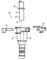
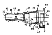
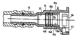
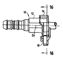
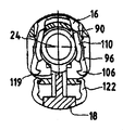
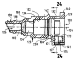
図1は、流体管路内に形成された急速継手10を示す。継手10は、主リテーナ部材16および別体の補助ラッチ/確認機構部材18によって合わせて固定されたほぼ円筒形のメスコネクタ本体12およびオス部材14で構成されている。オス部材14は、流体管路系の一部を形成する中空チューブの一端部に形成される。使用の際に、メスコネクタ本体12は、やはり流体管路系の一部である(図14に示されているような)チューブまたはホース13に接続される。メスコネクタ本体12およびオス部材14は、流体管路内に永久的であるが切り離し可能な接合部を形成するように接続可能である。   FIG. 1 shows a quick coupling 10 formed in a fluid line. The joint 10 includes a substantially cylindrical female connector body 12 and a male member 14 fixed together by a main retainer member 16 and a separate auxiliary latch / verification mechanism member 18. The male member 14 is formed at one end of a hollow tube that forms part of the fluid conduit system. In use, the female connector body 12 is connected to a tube or hose 13 (as shown in FIG. 14) that is also part of the fluid line system. The female connector body 12 and the male member 14 are connectable to form a permanent but detachable joint in the fluid conduit.

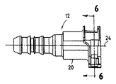
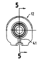
コネクタ本体12は、図2〜図6に詳細に示されている。コネクタ本体12は、ほぼ円筒形の段差付き外壁20およびほぼ円筒形の段差付き内壁22によって画定される。コネクタ本体12は、軸24に中心が位置して、好ましくはポリアミドなどのプラスチック材料製である。内壁22は、貫通内孔26を画定する。内孔26は、大径のオス部材受け取り端部28から小径のホース接続端部30まで、コネクタ本体12内を完全に貫通している。   The connector body 12 is shown in detail in FIGS. The connector body 12 is defined by a substantially cylindrical stepped outer wall 20 and a substantially cylindrical stepped inner wall 22. The connector body 12 is centered on the shaft 24 and is preferably made of a plastic material such as polyamide. The inner wall 22 defines a through hole 26. The inner hole 26 completely penetrates the connector body 12 from the large-diameter male member receiving end 28 to the small-diameter hose connection end 30.

コネクタ本体12の内壁22の直径の変化により、内孔26が4つの個別部分に分割される。オス部材受け取り端部28からホース接続端部30まで軸方向内向きに進むと、それらはリテーナハウジング部分32、シール室34、チューブ端部受け取り部36および流体通路38である。   Due to the change in the diameter of the inner wall 22 of the connector body 12, the inner hole 26 is divided into four individual parts. Proceeding axially inward from the male member receiving end 28 to the hose connection end 30, they are a retainer housing portion 32, a seal chamber 34, a tube end receiving portion 36 and a fluid passage 38.

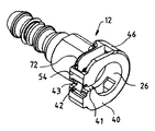
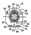
リテーナハウジング部分32は、オス部材受け取り端部28に隣接している。それは、上部支持部材44、2つの側部支持部材46、48、2つの中央支持部材50、52および2つの底部支持部材54、56によって内側リム42に連結されたC字形外側リム40によって画定される。外側リムスロット41が、C字形外側リム40の底部に画定される。ノッチ43が内側リム42の底部に画定される。上部支持部材44および2つの側部支持部材46、48間の空間が、2つの上部スロット58、60を画定している。2つの側部支持部材46、48および底部支持部材54、56間の空間が、2つの側部スロット62、64を画定している。2つの底部支持部材54、56間の空間が、底部スロット66を画定している。上部スロット58、60は、コネクタ本体12の中心軸24を横切る方向に主リテーナ16を受け取って、その位置決めを行う。側部スロット62、64および底部スロット66は、コネクタ本体の中心軸24を横切る方向に補助ラッチ/確認機構18を受け取って、その位置決めを行う。上部支持部材44は、湾曲した上面45を画定している。中央支持部材50、52の各々がロック肩部68、70を画定している。ロックリッジ72、74が、各底部支持部材54、56の外縁部から側方に延出している。   Retainer housing portion 32 is adjacent to male member receiving end 28. It is defined by a C-shaped outer rim 40 connected to the inner rim 42 by an upper support member 44, two side support members 46, 48, two central support members 50, 52 and two bottom support members 54, 56. The An outer rim slot 41 is defined at the bottom of the C-shaped outer rim 40. A notch 43 is defined at the bottom of the inner rim 42. The space between the upper support member 44 and the two side support members 46, 48 defines two upper slots 58, 60. The space between the two side support members 46, 48 and the bottom support members 54, 56 defines two side slots 62, 64. A space between the two bottom support members 54, 56 defines a bottom slot 66. The upper slots 58 and 60 receive the main retainer 16 in a direction crossing the central axis 24 of the connector body 12 and perform positioning thereof. The side slots 62, 64 and the bottom slot 66 receive and position the auxiliary latch / verification mechanism 18 in a direction across the central axis 24 of the connector body. The upper support member 44 defines a curved upper surface 45. Each of the central support members 50, 52 defines a locking shoulder 68, 70. Lock ridges 72, 74 extend laterally from the outer edge of each bottom support member 54, 56.

シール室34は、リテーナハウジング部分32の軸方向内側に形成されている。それは、内壁22の、リテーナハウジング部分32より小径の部分によって画定されて、円錐形肩部78から半径方向肩部80まで軸方向内向きに延在している。シール室34は、シール部材を収容し、それにより、コネクタ本体12およびオス部材14間を液密にするために設けられている。   The seal chamber 34 is formed inside the retainer housing portion 32 in the axial direction. It is defined by a portion of the inner wall 22 having a smaller diameter than the retainer housing portion 32 and extends axially inward from the conical shoulder 78 to the radial shoulder 80. The seal chamber 34 is provided in order to accommodate the seal member and thereby make the space between the connector main body 12 and the male member 14 liquid-tight.

チューブ端部受け取り部36は、シール室34の軸方向内側に形成されている。それは、内壁22の、シール室34より小径の部分によって画定されて、半径方向肩部80の小径端部から円錐形肩部82まで軸方向内向きに延在している。チューブ端部受け取り部36は、オス部材14の開放端部を受け取るために設けられている。   The tube end receiving portion 36 is formed on the inner side in the axial direction of the seal chamber 34. It is defined by a portion of the inner wall 22 that is smaller in diameter than the seal chamber 34 and extends axially inward from the smaller diameter end of the radial shoulder 80 to the conical shoulder 82. The tube end receiving portion 36 is provided to receive the open end of the male member 14.

流体通路38は、内壁22の最小直径の部分によって画定されている。それは、円錐形肩部82の小径端部からホース接続端部30まで続いている。外壁20の、流体通路38を取り囲む部分は、流体管路内の別の部品に接続しやすいように構成されている。たとえば、図示のコネクタ本体12は、フレキシブルホースとの接続用の特殊な形状になっている。フレキシブルホース内へ挿入しやすくするために、端部30に隣接して円錐形ノーズ84が形成されており、ホースをコネクタ本体上に保持するために、ランプ形バーブ86がノーズ84の外側に形成されている。所望ならば、外側Oリングシールを収容するために、溝88が画定される。   The fluid passage 38 is defined by the smallest diameter portion of the inner wall 22. It continues from the small diameter end of the conical shoulder 82 to the hose connection end 30. A portion of the outer wall 20 surrounding the fluid passage 38 is configured to be easily connected to another component in the fluid pipe. For example, the connector main body 12 shown in the figure has a special shape for connection with a flexible hose. A conical nose 84 is formed adjacent the end 30 for ease of insertion into the flexible hose, and a ramp-shaped barb 86 is formed outside the nose 84 to hold the hose on the connector body. Has been. If desired, a groove 88 is defined to accommodate the outer O-ring seal.

他の管路系構造に接続するために、別の外部形状をコネクタ本体12の流体通路端部付近に用いることができるであろう。たとえば、外壁20にねじを付けて、管路系部品を収容するハウジングのねじ付き内孔内に接続しやすくすることもできるであろう。   Other external shapes could be used near the fluid passage end of the connector body 12 to connect to other ductwork structures. For example, the outer wall 20 could be threaded to facilitate connection within a threaded bore in the housing that houses the ductwork components.

図1に示されているように、オス部材14は、剛性チューブの端部に形成されている。それは、開放したチューブ端部92から所定距離をおいて形成された半径方向拡大アップセット90を有する。チューブ端部92は、丸みを付けるか、またはテーパ状にして、コネクタ本体12内へのオス部材14の挿入し難さを軽減することができる。アップセット90およびチューブ端部92間に平滑な円筒形シール表面94が延在している。シール表面94の外径は、オス部材14の端部がチューブ端部受け取り部36内に滑りばめされるようなものでなければならない。   As shown in FIG. 1, the male member 14 is formed at the end of the rigid tube. It has a radially enlarged upset 90 formed at a distance from the open tube end 92. The tube end portion 92 can be rounded or tapered to reduce the difficulty of inserting the male member 14 into the connector body 12. A smooth cylindrical sealing surface 94 extends between the upset 90 and the tube end 92. The outer diameter of the sealing surface 94 should be such that the end of the male member 14 is slip fit into the tube end receiving portion 36.

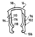
主「馬てい」形リテーナ16が、図7〜図9に詳細に示されている。それは好ましくは、プラスチックなどの弾性的な可撓性材料で形成される。主リテーナ16は、リテーナハウジング部分32の上部スロット58、60を通って延出して、コネクタ本体12に離脱可能に結合される。   The main “horsebed” retainer 16 is shown in detail in FIGS. It is preferably formed of an elastic flexible material such as plastic. The main retainer 16 extends through the upper slots 58, 60 of the retainer housing portion 32 and is releasably coupled to the connector body 12.

主リテーナ16には、横部材98から延出して、一端部でそれに接合されている1対の細長い略平行脚部96が設けられている。横部材98は、オス部材14の非アップセット外径にほぼ等しい離隔距離を脚部96間に設ける。脚部96は、上部スロット58、60の軸方向幅にほぼ等しいが、(隙間を与えるために)わずかに小さい軸方向幅を有する。脚部96の横幅は、上部スロット58、60の横幅より相当に狭く、それにより、(オス部材を挿抜するために)脚部96を外向きに拡開できるようにしている。   The main retainer 16 is provided with a pair of elongated substantially parallel leg portions 96 extending from the transverse member 98 and joined to one end thereof. The transverse member 98 provides a separation distance between the legs 96 that is approximately equal to the non-upset outer diameter of the male member 14. The leg 96 is approximately equal to the axial width of the upper slots 58, 60, but has a slightly smaller axial width (to provide clearance). The lateral width of the leg 96 is considerably narrower than the lateral width of the upper slots 58, 60, so that the leg 96 can be expanded outward (to insert and remove the male member).

横部材98は、脚部96より相当に広い軸方向幅を有する。図8に示されているように、横部材98は、脚部96の前面102と軸方向に整合しているが、脚部96の後面104を軸方向に越えて延出している。   The transverse member 98 has a substantially wider axial width than the leg 96. As shown in FIG. 8, the transverse member 98 is axially aligned with the front surface 102 of the leg 96, but extends beyond the rear surface 104 of the leg 96 in the axial direction.

各脚部96は、横部材98から遠い端部に形成されたラッチ106と、横部材98に隣接した端部の位置で後面104に形成された解除突出部108と、ラッチ106および横部材98間で前面102に形成された傾斜食い付き(lead)領域110とを備える。主リテーナ16をコネクタ本体12内へ完全に挿入すると、ラッチ106が主リテーナ16をコネクタ本体12に対して所定位置にロックする。ラッチ106によって画定されたラッチ縁部112が、コネクタ本体12の中央支持部材50、52によって画定されたロック肩部68、70に係合し、それにより、主リテーナ16を所定位置にロックする。   Each leg 96 includes a latch 106 formed at an end remote from the transverse member 98, a release protrusion 108 formed on the rear surface 104 at the end adjacent to the transverse member 98, the latch 106 and the transverse member 98. And an inclined lead region 110 formed in the front surface 102 therebetween. When the main retainer 16 is fully inserted into the connector body 12, the latch 106 locks the main retainer 16 in place with respect to the connector body 12. A latch edge 112 defined by the latch 106 engages a locking shoulder 68, 70 defined by the central support member 50, 52 of the connector body 12, thereby locking the main retainer 16 in place.

解除突出部108は、横部材98のすぐ下側で各脚部96の後面104から突出している。解除突出部108は、横部材98が脚部96から軸方向に延出する距離にほぼ等しい距離だけ、脚部96から軸方向に延出している。各突出部108にランプまたはカム面114が形成されている。組み付けられたとき、ランプ面114はコネクタ本体12の上部支持部材44の湾曲上面45のすぐ上方に載る。横部材98に圧力を加えて、主リテーナ16をコネクタ本体12内へさらに押し込むと、ランプ面114が上部支持部材44と接触して摺動する、すなわち、カム移動する。したがって、脚部96が拡開して、オス部材14を解放することができる。   The release protrusion 108 protrudes from the rear surface 104 of each leg 96 just below the lateral member 98. The release protrusion 108 extends in the axial direction from the leg 96 by a distance approximately equal to the distance that the lateral member 98 extends in the axial direction from the leg 96. A ramp or cam surface 114 is formed on each protrusion 108. When assembled, the ramp surface 114 rests just above the curved upper surface 45 of the upper support member 44 of the connector body 12. When pressure is applied to the lateral member 98 and the main retainer 16 is further pushed into the connector body 12, the ramp surface 114 slides in contact with the upper support member 44, that is, cams move. Therefore, the leg part 96 can expand and the male member 14 can be released.

食い付き領域110は、各脚部の前面102から半径方向および軸方向内向きに傾斜して、前面102および後面104のほぼ中間で終了する。食い付き領域110間の空間は、前面102付近で最大になる。この場合、その空間は、オス部材14に形成されたアップセット90の直径にほぼ等しい。食い付き領域110の後縁部116において、食い付き領域110間の空間は、オス部材14の(非アップセット)外径にほぼ等しい。食い付き領域110の、ラッチ106により近い部分は118の位置で内向きに湾曲し、それにより、オス部材アップセット90の環状輪郭に一致している。これは、コネクタ本体12内を通るオス部材14の案内およびセンタリングを助ける。   The biting area 110 slopes radially and axially inward from the front face 102 of each leg and ends approximately halfway between the front face 102 and the rear face 104. The space between the biting areas 110 is maximized near the front surface 102. In this case, the space is approximately equal to the diameter of the upset 90 formed in the male member 14. At the trailing edge 116 of the biting area 110, the space between the biting areas 110 is approximately equal to the (non-upset) outer diameter of the male member 14. The portion of the biting area 110 that is closer to the latch 106 is curved inward at 118, thereby matching the annular profile of the male member upset 90. This helps guide and center the male member 14 through the connector body 12.

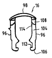
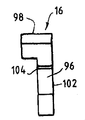
補助ラッチ/確認機構18が、図10〜13に詳細に示されている。それは好ましくは、プラスチックなどの弾性的な可撓性材料で形成される。補助ラッチ/確認機構18は、リテーナビーム119と、連結部材124によって結合された1対の細長い略平行フィンガ122とを有する。連結部材124は、矩形のノッチ125を画定する。ノッチ125は、ねじ回しの端部などの、矩形断面を有する刃(a knifed edge)をそれに挿入して、補助ラッチ/確認機構18を(図17に示されているような)ラッチ位置から(図16に示されているような)ラッチ解除位置にこじるために必要なてこの作用を与えることができる形状になっている。リテーナビーム119の前部から軸方向にチューブ確認機構126が延出している。連結部材の後部から軸方向に保持リム128が延出している。   The auxiliary latch / verification mechanism 18 is shown in detail in FIGS. It is preferably formed of an elastic flexible material such as plastic. The auxiliary latch / verification mechanism 18 includes a retainer beam 119 and a pair of elongated generally parallel fingers 122 joined by a connecting member 124. The connecting member 124 defines a rectangular notch 125. The notch 125 inserts a knifed edge, such as the end of a screwdriver, into the rectangular cross section to move the auxiliary latch / verifier mechanism 18 from the latched position (as shown in FIG. 17) ( The shape is such that it can provide the necessary leverage to pry into the unlatched position (as shown in FIG. 16). A tube confirmation mechanism 126 extends in the axial direction from the front portion of the retainer beam 119. A holding rim 128 extends in the axial direction from the rear portion of the connecting member.

リテーナビーム119は、横方向拡大部分120および細幅部分121を有する。拡大部分120の横幅は、底部スロット66の横幅よりわずかに狭い。細幅部分121の横幅は、外側リムスロット41の横幅よりわずかに狭い。拡大部分120は、オス部材14のアップセット90に当接する当接表面123を画定する。リテーナビーム119の半径方向内側表面は、オス部材14を形成するチューブの外面の曲率に一致するように湾曲している。   The retainer beam 119 has a laterally enlarged portion 120 and a narrow portion 121. The width of the enlarged portion 120 is slightly narrower than the width of the bottom slot 66. The width of the narrow portion 121 is slightly narrower than the width of the outer rim slot 41. The enlarged portion 120 defines an abutment surface 123 that abuts the upset 90 of the male member 14. The radially inner surface of the retainer beam 119 is curved to match the curvature of the outer surface of the tube forming the male member 14.

各フィンガ122は、連結部材124から遠い端部に形成されたフック130を有する。補助ラッチ/確認機構がラッチ解除位置にあるとき、フック130によって画定されたノッチ132が、底部支持部材54、56によって画定されたロックリッジ72、74に係合し、それにより、補助ラッチ/確認機構18をコネクタ本体12に固定する。フック130および連結部材124間に位置する各フィンガ122の内面は、ランプ面134および横方向拡大表面136を画定する。2つのフィンガのランプ面134間の距離は、ロックリッジ72、74間の距離より短い。2つのフィンガの横方向拡大表面136間の距離は、ロックリッジ72、74間の距離にほぼ等しい。さらに、フィンガ122の内面間の最も狭い距離は、主リテーナ16の脚部96の外面間の距離よりわずかに長い。フィンガ122の軸方向幅は、脚部96の軸方向幅にほぼ等しい。   Each finger 122 has a hook 130 formed at the end remote from the connecting member 124. When the auxiliary latch / verification mechanism is in the unlatched position, the notch 132 defined by the hook 130 engages the lock ridges 72, 74 defined by the bottom support members 54, 56, thereby assisting in the auxiliary latch / verification. The mechanism 18 is fixed to the connector body 12. The inner surface of each finger 122 located between the hook 130 and the connecting member 124 defines a ramp surface 134 and a laterally enlarged surface 136. The distance between the ramp surfaces 134 of the two fingers is shorter than the distance between the lock ridges 72, 74. The distance between the laterally enlarged surfaces 136 of the two fingers is approximately equal to the distance between the lock ridges 72, 74. Further, the narrowest distance between the inner surfaces of the fingers 122 is slightly longer than the distance between the outer surfaces of the legs 96 of the main retainer 16. The axial width of the finger 122 is approximately equal to the axial width of the leg 96.

チューブ確認機構126は、ほぼ月形である。チューブ確認機構126の半径方向内側表面は、第1湾曲面138および第2湾曲面140を有する。第1湾曲面138は、オス部材14を形成するチューブの外面の曲率に一致するように湾曲している。第2湾曲面140は、アップセット90の外面の曲率に一致するように湾曲している。   The tube confirmation mechanism 126 is substantially moon-shaped. The radially inner surface of the tube confirmation mechanism 126 has a first curved surface 138 and a second curved surface 140. The first curved surface 138 is curved so as to match the curvature of the outer surface of the tube forming the male member 14. Second curved surface 140 is curved to match the curvature of the outer surface of upset 90.

保持リム128は、連結部材124の後部から軸方向に延出している。リブ142が、保持リム28の前面を連結部材124の後面に接続している。リブ142の横幅は、内側リム42のノッチ43の横幅よりわずかに狭い。リブ142の軸方向長さは、内側リム42の軸方向厚さよりわずかに長い。保持リム128の半径方向内側縁部に縁部144が画定されている。縁部144の曲率は、外壁20の、シール室34を取り囲む部分の曲率に一致している。縁部144の曲率は、上向きの圧力が補助ラッチ/確認機構をラッチ解除位置に解放して、オス部材の作動を可能にすることができるような湾曲である。   The holding rim 128 extends in the axial direction from the rear portion of the connecting member 124. A rib 142 connects the front surface of the holding rim 28 to the rear surface of the connecting member 124. The lateral width of the rib 142 is slightly narrower than the lateral width of the notch 43 of the inner rim 42. The axial length of the rib 142 is slightly longer than the axial thickness of the inner rim 42. An edge 144 is defined at the radially inner edge of the retaining rim 128. The curvature of the edge portion 144 matches the curvature of the portion of the outer wall 20 surrounding the seal chamber 34. The curvature of the edge 144 is curved such that upward pressure can release the auxiliary latch / verifier mechanism to the unlatched position, allowing the male member to operate.

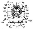
図14に示されているように、シール室34内に2つのOリングシール146、148が配置されて、剛性スペーサリング150によって分離されている。Oリング146、148は、シール室34の内側およびオス部材14のシール表面94の周囲に締まりばめされる寸法である。Oリング146、148は、中空のスペーサスリーブ152によってシール室34内に固定されている。スペーサスリーブ152には、内壁22の円錐形肩部78に当接し、それにより、スリーブ152を内孔26内に位置決めする円錐形拡大端部154が設けられている。スペーサスリーブ152を内孔26内に確実に固定するために、スリーブ156の外周に隆起環状部分156が形成されており、内壁22に対応の環状リセス158が形成されている(図5を参照)。隆起部分156は、内壁22に形成されたリセス158内にはめ合い状に受け取られ、それによってスリーブ152を所定位置にロックするであろう。   As shown in FIG. 14, two O-ring seals 146, 148 are disposed in the seal chamber 34 and separated by a rigid spacer ring 150. The O-rings 146, 148 are dimensioned to be an interference fit around the inside of the seal chamber 34 and around the seal surface 94 of the male member 14. The O-rings 146 and 148 are fixed in the seal chamber 34 by a hollow spacer sleeve 152. The spacer sleeve 152 is provided with a conical enlarged end 154 that abuts the conical shoulder 78 of the inner wall 22, thereby positioning the sleeve 152 within the inner bore 26. In order to securely fix the spacer sleeve 152 in the inner hole 26, a raised annular portion 156 is formed on the outer periphery of the sleeve 156, and a corresponding annular recess 158 is formed on the inner wall 22 (see FIG. 5). . The raised portion 156 will be received in a recess 158 formed in the inner wall 22 thereby locking the sleeve 152 in place.

オス部材14をコネクタ本体12に挿入する前に、最初に主リテーナ16をコネクタ本体12に取り付ける。主リテーナ16の脚部96をリテーナハウジング部分32の上部スロット58、60から挿入する。主リテーナ16は、横部材98および解除突出部108が上部支持部材44の上方に位置するような向きにされ、脚部96の食い付き領域110がオス部材受け取り端部28と向き合う。   Before inserting the male member 14 into the connector main body 12, the main retainer 16 is first attached to the connector main body 12. Legs 96 of main retainer 16 are inserted through upper slots 58, 60 of retainer housing portion 32. The main retainer 16 is oriented such that the transverse member 98 and the release protrusion 108 are positioned above the upper support member 44, and the biting area 110 of the leg 96 faces the male member receiving end 28.

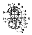
横部材98に下向き力を加えることにより、上部スロット58、60内への脚部96の挿入が容易になる。本特許出願で規定される「下向き力」とは、コネクタ本体12の方に向けて加えられる力である。脚部96が中央支持部材50、52の側部と接触したとき、下向き力を増加させる必要がある。十分な下向き力を加えると、脚部96の丸み付き端部が中央支持部材50、52の側部に接しながら摺動し、脚部96を拡開させて、脚部96が中央支持部材50、52を通過できるようにする。脚部が中央支持部材50、52を通り過ぎると、脚部96は内向きに跳ねて、ラッチ縁部112が底部支持部材78のロック肩部68、70の下側に配置され、それにより、主リテーナ16がコネクタ本体12に固定される。適切に取り付けられた主リテーナ16が、図15〜図17に示されている。取り付け位置では、側部から見たとき、主リテーナ16の脚部96は、内孔26の軸24に対してほぼ垂直である(図1および図15を参照)。前方または後方から見たとき、脚部96は内孔26の軸24からほぼ等間隔に位置する(図16および図17を参照)。   By applying a downward force to the transverse member 98, the leg 96 can be easily inserted into the upper slots 58,60. The “downward force” defined in this patent application is a force applied toward the connector body 12. When the leg 96 comes into contact with the sides of the central support members 50, 52, it is necessary to increase the downward force. When a sufficient downward force is applied, the rounded end portion of the leg portion 96 slides in contact with the side portions of the central support members 50, 52 to expand the leg portion 96, and the leg portion 96 becomes the central support member 50. , 52 through. As the leg passes the central support member 50, 52, the leg 96 springs inward and the latch edge 112 is located under the locking shoulders 68, 70 of the bottom support member 78, so that the main The retainer 16 is fixed to the connector body 12. A properly installed main retainer 16 is shown in FIGS. In the installed position, when viewed from the side, the leg 96 of the main retainer 16 is substantially perpendicular to the axis 24 of the inner bore 26 (see FIGS. 1 and 15). When viewed from the front or rear, the leg portions 96 are located at approximately equal intervals from the shaft 24 of the inner hole 26 (see FIGS. 16 and 17).

主リテーナ16をコネクタ本体12に適切に取り付けてから、次にオス部材14をコネクタ本体12に挿入する。脚部96間の空間がオス部材14の非アップセット外径にほぼ等しいので、オス部材14のシール表面94は、抵抗をほとんど、またはまったく受けないで、脚部96間を通ってシール室34に入る。オス部材14のアップセット90が脚部96と接触するとき、挿入に対する抵抗が発生する。十分な軸方向内向きの力を加えると、脚部96の食い付き領域110によってアップセット90が脚部間を通過することができる。アップセット90が脚部96間を通過するとき、それは食い付き領域110に沿って載って、脚部96を半径方向外向きにたわませる。アップセット90が脚部96を通過すると、脚部96はアップセット90の背後でロック位置に跳ね返る。脚部96の後面104がアップセットに当接し、それにより、後に誤ってオス部材14がコネクタ本体12から抜けることを防止する。スペーサスリーブ152は、コネクタ本体12の内壁22上に画定された円錐形肩部78と協働して、オス部材130がロック位置からさらに内向きに挿入されることを防止する。   After the main retainer 16 is properly attached to the connector body 12, the male member 14 is then inserted into the connector body 12. Since the space between the legs 96 is approximately equal to the non-upset outer diameter of the male member 14, the sealing surface 94 of the male member 14 passes between the legs 96 with little or no resistance, and the sealing chamber 34. to go into. When the upset 90 of the male member 14 contacts the leg 96, resistance to insertion occurs. When sufficient axial inward force is applied, the biting area 110 of the leg 96 allows the upset 90 to pass between the legs. As the upset 90 passes between the legs 96, it rests along the biting area 110 and deflects the legs 96 radially outward. As the upset 90 passes the leg 96, the leg 96 rebounds to the locked position behind the upset 90. The rear surface 104 of the leg 96 abuts the upset, thereby preventing the male member 14 from accidentally coming off the connector body 12 later. The spacer sleeve 152 cooperates with a conical shoulder 78 defined on the inner wall 22 of the connector body 12 to prevent the male member 130 from being inserted further inward from the locked position.

横部材98に下向き力を加えることによって、オス部材14をロック位置から解放することができる。横部材98に下向き力を加えることにより、解除突出部108がコネクタ本体12の上部支持部材44の湾曲上面45と接触する。下向き力を加え続けると、解除突出部108のランプ面114が上部支持部材44に接しながら摺動またはカム移動して、脚部96を横方向に拡開させる。最終的に、脚部96は、アップセット90が脚部96間を通過するのに十分な距離だけ拡開するであろう。次に、オス部材14をコネクタ本体12から引き抜くことができる。部材14をコネクタ本体12から引き抜いて主リテーナ16が弛緩すると、主リテーナ16はその通常設置位置に戻る。   By applying a downward force to the lateral member 98, the male member 14 can be released from the locked position. By applying a downward force to the lateral member 98, the release protrusion 108 comes into contact with the curved upper surface 45 of the upper support member 44 of the connector body 12. When the downward force is continuously applied, the ramp surface 114 of the release protrusion 108 slides or cams while being in contact with the upper support member 44, and the leg 96 is expanded laterally. Eventually, the legs 96 will expand a distance sufficient for the upset 90 to pass between the legs 96. Next, the male member 14 can be pulled out from the connector body 12. When the member 14 is pulled out of the connector body 12 and the main retainer 16 is relaxed, the main retainer 16 returns to its normal installation position.

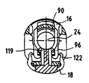
補助ラッチ/確認機構18を、(図15および図16に示されているように)ロックリッジ72、74がノッチ132内に位置するラッチ解除位置から、(図17に示されているような)ラッチ位置に配置することにより、結合が完了する。補助ラッチ/確認機構18をラッチ位置に配置するために、連結部材124に下向き力を加える。十分な下向き力により、フィンガ122のランプ面134がロックリッジ72、74の側部を摺動してフィンガ122を拡開させ、フィンガが底部支持部材54、56を通過できるようにする。図16および図17に示されているように、オス部材14をコネクタ本体12内に適切に挿入すると、補助ラッチ/確認機構は、補助ラッチ/確認機構18のフィンガ122の一部分が主リテーナ16の脚部96の横方向外側に位置する位置へ移動することができる。同時に、リテーナビーム119およびチューブ確認機構126は、オス部材14の方に向かって半径方向内向きに移動し、保持リム128は、シール室34を取り囲んでいる外壁20の方に向かって半径方向内向きに移動する。   The auxiliary latch / verification mechanism 18 is moved from the unlatched position (as shown in FIG. 17) from the latched position where the lock ridges 72, 74 are located in the notch 132 (as shown in FIGS. 15 and 16). By placing it in the latch position, the coupling is completed. A downward force is applied to the connecting member 124 to place the auxiliary latch / verification mechanism 18 in the latched position. With sufficient downward force, the ramp surface 134 of the finger 122 slides on the sides of the lock ridges 72, 74 to widen the finger 122 and allow the finger to pass through the bottom support members 54, 56. As shown in FIGS. 16 and 17, when the male member 14 is properly inserted into the connector body 12, the auxiliary latch / verification mechanism is configured such that a portion of the finger 122 of the auxiliary latch / verification mechanism 18 is in contact with the main retainer 16. It is possible to move to a position located outside the leg 96 in the lateral direction. At the same time, the retainer beam 119 and the tube verification mechanism 126 move radially inward toward the male member 14, and the retaining rim 128 moves radially inward toward the outer wall 20 surrounding the seal chamber 34. Move in the direction.

補助ラッチ/確認機構18をコネクタ本体12内へ完全に挿入すると、ロックリッジ72、74はフィンガ122のランプ面134を越えて、横方向拡大表面136間に位置する。補助ラッチ/確認機構18のフィンガ122は、図17に示されているように、ラッチ位置へ横方向内向きに跳ねる。側部から見たとき、補助ラッチ/確認機構18のフィンガ122は、内孔26の軸24に対してほぼ垂直である(図1および図15を参照)。前方または後方から見たとき、フィンガ122は内孔26の軸24からほぼ等間隔に位置する(図16および図17を参照)。ラッチ位置では、補助ラッチ/確認機構18の各フィンガ122の一部分が、主リテーナ16の対応脚部96の横方向外側に位置する。脚部96に対するフィンガ122の位置により、脚部96が誤って横方向外側に移動してオス部材14をロック位置から解放することが防止される。ラッチ位置では、リテーナビーム119の後面が、オス部材14のアップセット90に軸方向に当接した関係にある。リテーナビーム119およびアップセット90間のこの軸方向当接関係により、主リテーナ16が故障した場合でも、オス部材14をコネクタ部材12内に保持するという補助ラッチ機能が補助ラッチ/確認機構18に与えられる。   When the auxiliary latch / verification mechanism 18 is fully inserted into the connector body 12, the lock ridges 72, 74 are positioned between the laterally enlarged surfaces 136 beyond the ramp surface 134 of the finger 122. The fingers 122 of the auxiliary latch / verification mechanism 18 spring laterally inward to the latched position, as shown in FIG. When viewed from the side, the finger 122 of the auxiliary latch / verification mechanism 18 is substantially perpendicular to the axis 24 of the bore 26 (see FIGS. 1 and 15). When viewed from the front or rear, the fingers 122 are located at approximately equal intervals from the shaft 24 of the inner hole 26 (see FIGS. 16 and 17). In the latched position, a portion of each finger 122 of the auxiliary latch / verification mechanism 18 is located laterally outward of the corresponding leg 96 of the main retainer 16. The position of the finger 122 relative to the leg 96 prevents the leg 96 from moving laterally outward and releasing the male member 14 from the locked position. In the latch position, the rear surface of the retainer beam 119 is in contact with the upset 90 of the male member 14 in the axial direction. This axial contact relationship between the retainer beam 119 and the upset 90 provides the auxiliary latch / verification mechanism 18 with an auxiliary latch function of holding the male member 14 in the connector member 12 even if the main retainer 16 fails. It is done.

保持リム128およびチューブ確認機構126は、補助ラッチ/確認機構18をコネクタ本体12に対して位置決めするのに役立つ。ラッチ位置では、リブ142が、内側リム42の底部に画定されたノッチ43を通って延出する。保持リム128は、コネクタ本体12の内側リム42の軸方向のすぐ後側、かつシール室34を取り囲む外壁20の半径方向のすぐ外側に位置する。連結部材124は、内側リム42の軸方向のすぐ前方に位置する。補助ラッチ/確認機構18の保持リム128および連結部材124が内側リム42を挟み、それにより、補助ラッチ/確認機構18をコネクタ本体12に対して軸方向に位置決めする。リテーナビーム119の細幅部分121が、外側リムスロット41に通される。チューブ確認機構126は、コネクタ本体12の外側リム40のすぐ前方、かつオス部材14を形成するチューブの半径方向のすぐ外側に位置する。保持リム128がコネクタ本体12の半径方向のすぐ外側に位置し、チューブ確認機構126がチューブの半径方向のすぐ外側に位置するので、保持リム128およびチューブ確認機構126は、補助ラッチ/確認機構18がラッチ位置に入った後に傾斜することを防止する。   The retaining rim 128 and tube verification mechanism 126 help to position the auxiliary latch / verification mechanism 18 relative to the connector body 12. In the latched position, the rib 142 extends through a notch 43 defined in the bottom of the inner rim 42. The holding rim 128 is positioned immediately rearward in the axial direction of the inner rim 42 of the connector body 12 and immediately outside in the radial direction of the outer wall 20 surrounding the seal chamber 34. The connecting member 124 is located immediately in front of the inner rim 42 in the axial direction. The holding rim 128 and the connecting member 124 of the auxiliary latch / verification mechanism 18 sandwich the inner rim 42, thereby positioning the auxiliary latch / verification mechanism 18 in the axial direction with respect to the connector body 12. A narrow portion 121 of the retainer beam 119 is passed through the outer rim slot 41. The tube confirmation mechanism 126 is located just in front of the outer rim 40 of the connector body 12 and just outside in the radial direction of the tube forming the male member 14. Since the retaining rim 128 is positioned just outside the connector body 12 in the radial direction and the tube verification mechanism 126 is positioned just outside the radial of the tube, the retention rim 128 and the tube verification mechanism 126 are connected to the auxiliary latch / verification mechanism 18. Prevents tilting after entering the latched position.

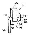
図18は、オス部材14がコネクタ本体12内に適切に挿入されなかったときの状況を示す。そのような状況では、オス部材14は、アップセット90が主リテーナ16の脚部96を通り過ぎるほど十分にはコネクタ本体12内に挿入されていない。脚部96がまだ拡開した状態にあり、フィンガ122の端部が主リテーナ16のまだ拡開状態にある脚部96に当接するので、補助ラッチ/確認機構18のフィンガ122を半径方向内向きにコネクタ本体12内へ挿入することができない。さらに、オス部材14がコネクタ本体12内へ不十分に挿入された状態では、アップセット90は補助ラッチ/確認機構18のリテーナビーム119の半径方向のすぐ内側に位置する。リテーナビーム119の半径方向内側面がアップセット90の半径方向外面に当接することにより、補助ラッチ/確認機構をコネクタ本体12内へ半径方向内向きに挿入することもできなくなる。このように補助ラッチ/確認機構18がラッチ位置へ半径方向内向きに移動することができないことにより、オス部材14がコネクタ本体12内へ十分には挿入されていないことをユーザに確認させる。他方、オス部材14がコネクタ本体12内へ十分に挿入されており、それにより、アップセット90が主リテーナ16の脚部96を通り越えた場合、補助ラッチ/確認機構のフィンガ122の端部が主リテーナ16の脚部96に当接しないと共に、リテーナ確認機構119の半径方向内側表面がアップセット90の半径方向外面に当接しないで、補助ラッチ/確認機構18がラッチ位置へ移動できるようにする。このように補助ラッチ/確認機構18がラッチ位置へ半径方向内向きに移動できることにより、オス部材14がコネクタ本体12内へ十分に挿入されていることをユーザに確認させる。   FIG. 18 shows a situation when the male member 14 is not properly inserted into the connector body 12. In such a situation, the male member 14 has not been inserted into the connector body 12 sufficiently such that the upset 90 has passed the leg 96 of the main retainer 16. Since the leg 96 is still in an expanded state and the end of the finger 122 abuts the leg 96 in the expanded state of the main retainer 16, the finger 122 of the auxiliary latch / verification mechanism 18 is directed radially inward. Cannot be inserted into the connector body 12. Further, in the state where the male member 14 is insufficiently inserted into the connector body 12, the upset 90 is located immediately inside the retainer beam 119 of the auxiliary latch / verification mechanism 18. Because the radially inner surface of the retainer beam 119 abuts the radially outer surface of the upset 90, the auxiliary latch / verification mechanism cannot be inserted radially inward into the connector body 12. In this way, the auxiliary latch / confirmation mechanism 18 cannot move radially inward to the latch position, thereby allowing the user to confirm that the male member 14 is not sufficiently inserted into the connector body 12. On the other hand, when the male member 14 is fully inserted into the connector body 12 so that the upset 90 passes over the leg 96 of the main retainer 16, the end of the finger 122 of the auxiliary latch / verification mechanism is The auxiliary latch / verification mechanism 18 can move to the latch position without contacting the leg 96 of the main retainer 16 and without the radially inner surface of the retainer verification mechanism 119 contacting the radial outer surface of the upset 90. To do. Thus, the auxiliary latch / confirmation mechanism 18 can move radially inward to the latch position, thereby allowing the user to confirm that the male member 14 is sufficiently inserted into the connector body 12.

図19〜図30は、図1〜図18の継手には存在しない特徴を含めた本発明の特徴を備える急速継手を開示している。構成部品も後述するようにわずかに修正されているが、実質的には第1の例示的な実施形態の利点を与える。   19-30 disclose a quick joint with features of the present invention, including features that are not present in the joint of FIGS. The components are also slightly modified as described below, but substantially provide the advantages of the first exemplary embodiment.

本実施形態の追加の特徴は、急速継手を完全に組み付けた最終ラッチ状態で輸送して流体管路内に設置することができることである。保持およびラッチ構成部品のすべては、それらがオス部材をコネクタ本体内に固定しようとするとき、コネクタ本体内の所定位置にある。この特徴は、補助ラッチ確認機構がコネクタ本体に接続されて最終ラッチ位置に配置された状態で、剛性チューブをコネクタ本体に結合することができるという点で重要である。   An additional feature of this embodiment is that the quick coupling can be transported in a final latched state and installed in the fluid line. All of the holding and latching components are in place within the connector body when they attempt to secure the male member within the connector body. This feature is important in that the rigid tube can be coupled to the connector body with the auxiliary latch verification mechanism connected to the connector body and positioned in the final latch position.

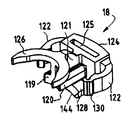
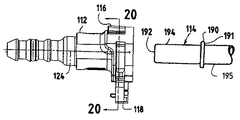
次に図19〜図30に目を向けると、図19は、流体管路内で切り離し可能な接続を行う急速継手を示す。継手は、主リテーナ部材116および別体の補助ラッチ/確認機構部材118によって合わせて取り外し可能に固定されたほぼ円筒形のメスコネクタ本体112およびオス部材114で構成されている。オス部材114は、流体管路系の一部を形成する中空チューブの端部に形成される。使用の際に、メスコネクタ本体112は、やはり流体管路系の一部である(図14に示されているような)チューブまたはホース13に接続される。メスコネクタ本体112およびオス部材114は、流体管路内で永久的であるが切り離し可能な接合を行うように接続可能である。   Turning now to FIGS. 19-30, FIG. 19 shows a quick coupling that provides a severable connection within a fluid line. The joint is comprised of a substantially cylindrical female connector body 112 and a male member 114 that are removably secured together by a main retainer member 116 and a separate auxiliary latch / verifier mechanism member 118. The male member 114 is formed at the end of a hollow tube that forms part of the fluid line system. In use, the female connector body 112 is connected to a tube or hose 13 (as shown in FIG. 14) that is also part of the fluid line system. The female connector body 112 and the male member 114 are connectable to provide a permanent but detachable joint within the fluid conduit.

コネクタ本体112は、図22〜図24に詳細に示されている。コネクタ本体112は、ほぼ円筒形の段差付き外壁120およびほぼ円筒形の段差付き内壁122によって画定されている。図示のコネクタ本体112は、好ましくはポリアミドなどのプラスチック材料で成形される。本体外側は、本発明から逸脱することなく任意の所望形状をとることができることを理解されたい。たとえば、コネクタ本体には一般的な形状である、端部間に90°のベンドを有することができるであろう。   The connector body 112 is shown in detail in FIGS. The connector body 112 is defined by a substantially cylindrical stepped outer wall 120 and a substantially cylindrical stepped inner wall 122. The illustrated connector body 112 is preferably molded from a plastic material such as polyamide. It should be understood that the outside of the body can take any desired shape without departing from the invention. For example, a connector body could have a 90 ° bend between the ends, which is a common shape.

内壁122は、長手軸124に中心が位置する貫通内孔126を画定する。本明細書で使用される「軸方向」という用語は、中心軸124に沿っていることを意味することが理解される。「横方向」、「横方向に」、「横断方向」および「横断方向に」という用語は、軸124に対してほぼ垂直な平面上での左右方向を意味する。横断方向移動は、ほぼ軸124に対して垂直な平面上で軸124に接近およびそれから離れる方向の移動を意味する。横方向移動は、軸124に対してほぼ垂直な平面上で軸124に接近およびそれから離れる左右方向移動を意味する。コネクタ本体112の内孔126は、大径のオス部材受け取り端部128から小径のホース接続端部130まで、コネクタ本体112内を完全に貫通している。   Inner wall 122 defines a through-bore 126 centered on longitudinal axis 124. It will be understood that the term “axial” as used herein means along the central axis 124. The terms “lateral”, “laterally”, “transverse” and “transversely” refer to the left-right direction on a plane substantially perpendicular to the axis 124. Transverse movement means movement in a direction toward and away from axis 124 in a plane that is substantially perpendicular to axis 124. Lateral movement means lateral movement toward and away from axis 124 in a plane substantially perpendicular to axis 124. The inner hole 126 of the connector main body 112 completely penetrates the connector main body 112 from the large-diameter male member receiving end portion 128 to the small-diameter hose connection end portion 130.

コネクタ本体112の内壁122の直径の変化により、貫通内孔126が4つの個別部分に分割される。オス部材受け取り端部128からホース接続端部130まで軸方向内向きに進むと、それらはリテーナハウジング部分132、シール室134、チューブ端部受け取り部136および流体通路138である。   By changing the diameter of the inner wall 122 of the connector body 112, the through-hole 126 is divided into four individual parts. Proceeding axially inwardly from the male member receiving end 128 to the hose connection end 130 are a retainer housing portion 132, a seal chamber 134, a tube end receiving portion 136 and a fluid passage 138.

リテーナハウジング部分132は、オス部材受け取り端部128に隣接している。それは、オス受け取り端部128に貫通内孔126への入口を画定する横断方向の平坦な前向き表面129を有する軸方向外側リム140によって画定される。図24に示されているように、軸方向外側リム140は、上部支持部材144、2つの側部支持部材146、2つの中央支持部材150および2つの底部支持部材154によって軸方向内側リム142に連結されている。底支持部材154の位置で、リム140および142間に底壁157が延在している。軸方向外側リム140の位置で底壁157にノッチ141が画定されている。   Retainer housing portion 132 is adjacent to male member receiving end 128. It is defined by an axially outer rim 140 having a transverse flat forward surface 129 that defines an entrance to the through bore 126 at the male receiving end 128. As shown in FIG. 24, the axial outer rim 140 is connected to the axial inner rim 142 by a top support member 144, two side support members 146, two central support members 150 and two bottom support members 154. It is connected. A bottom wall 157 extends between the rims 140 and 142 at the position of the bottom support member 154. A notch 141 is defined in the bottom wall 157 at the location of the axially outer rim 140.

上部支持部材144および2つの側部支持部材146間の空間が、1対の第1の、すなわち上部スロット158を画定している。2つの中央支持部材150および2つの底部支持部材154間の空間が、上部支持部材144と真向かいの第2の底部スロット166を画定している。これらのスロットは、貫通内孔126に開いている。2つの側部支持部材146および底部支持部材154間の空間が、1対の第2の側部スロット162を画定している。   The space between the upper support member 144 and the two side support members 146 defines a pair of first or upper slots 158. The space between the two central support members 150 and the two bottom support members 154 defines a second bottom slot 166 that is directly opposite the top support member 144. These slots are opened in the through hole 126. The space between the two side support members 146 and the bottom support member 154 defines a pair of second side slots 162.

上部スロット158は、コネクタ本体112の中心軸24を横切る方向に主リテーナ116を受け取って、その位置決めを行う。底部スロット166は、コネクタ本体112の中心軸24を横切る方向に補助ラッチ/確認機構118を受け取って、その位置決めを行う。容易に理解されるように、主リテーナ116および補助ラッチ/確認機構118の両方の構成要素は、側部スロット162内にある。   The upper slot 158 receives the main retainer 116 in a direction crossing the central axis 24 of the connector main body 112 and positions it. The bottom slot 166 receives and positions the auxiliary latch / verification mechanism 118 in a direction across the central axis 24 of the connector body 112. As will be readily appreciated, the components of both the main retainer 116 and the auxiliary latch / verification mechanism 118 are in the side slot 162.

底部スロット166は、図22〜図24に見られるように、中央支持部材150の離間表面167と底部支持部材154の離間表面169との間に横方向に延在する拡大部分と、図23に1つが示されている横方向表面175間に横断方向に延在する、図22および図23に最もわかりやすく見られる細幅部分とを有する。表面175は、ノッチ141と内部内孔126との間に延在して、中心線すなわち中心軸124からほぼ等間隔にあって互いに平行である。   The bottom slot 166 includes an enlarged portion extending laterally between the spacing surface 167 of the central support member 150 and the spacing surface 169 of the bottom support member 154, as seen in FIGS. One has a narrow portion that is seen most clearly in FIGS. 22 and 23, extending transversely between the lateral surfaces 175 shown. The surfaces 175 extend between the notches 141 and the inner bore 126 and are substantially equidistant from the center line or center axis 124 and parallel to each other.

底部スロットの断面は、略「T」字形である。底部スロット166の内壁面171が、底部スロット166の最も内側の表面を画定する。図23に見られるように、前すなわち外壁面173が、底部スロット166の前方すなわち前壁を画定する。リテーナハウジング部分132は、リテーナハウジング部分132の壁面171の軸方向内側の位置で貫通穴124内にチューブアップセット受け取り室も画定する。   The cross section of the bottom slot is generally “T” shaped. The inner wall surface 171 of the bottom slot 166 defines the innermost surface of the bottom slot 166. As seen in FIG. 23, the front or outer wall 173 defines the front or front wall of the bottom slot 166. The retainer housing portion 132 also defines a tube upset receiving chamber in the through hole 124 at a position axially inward of the wall surface 171 of the retainer housing portion 132.

上部支持部材144は、湾曲上面145を画定している。中央支持部材150の各々がロック肩部168を画定している。ロックリッジ172が、各底部支持部材154の外縁部から横方向に延出している。   Upper support member 144 defines a curved upper surface 145. Each central support member 150 defines a locking shoulder 168. A lock ridge 172 extends laterally from the outer edge of each bottom support member 154.

シール室134は、リテーナハウジング部分132の軸方向内側に形成されている。それは、内壁122の、リテーナハウジング部分132より小径の部分によって画定されて、円錐形肩部178から半径方向肩部180まで軸方向内向きに延在している。図1〜図18の実施形態に関連して説明したように、シール室134は、シール部材を収容し、それにより、コネクタ本体112およびオス部材114間を液密にするために設けられている。   The seal chamber 134 is formed inside the retainer housing portion 132 in the axial direction. It is defined by a portion of the inner wall 122 having a smaller diameter than the retainer housing portion 132 and extends axially inward from the conical shoulder 178 to the radial shoulder 180. As described in connection with the embodiment of FIGS. 1-18, the seal chamber 134 is provided to house the seal member and thereby make the connector body 112 and the male member 114 fluid-tight. .

チューブ端部受け取り部136は、シール室134の軸方向内側に形成されている。それは、内壁122の、シール室34より小径の部分によって画定されて、半径方向肩部180の小径端部から円錐形肩部182まで軸方向内向きに延在している。チューブ端部受け取り部136は、オス部材114を受け取って導く、すなわち案内することができる寸法である。   The tube end receiving portion 136 is formed inside the seal chamber 134 in the axial direction. It is defined by a portion of the inner wall 122 that is smaller in diameter than the seal chamber 34 and extends axially inward from the small diameter end of the radial shoulder 180 to the conical shoulder 182. The tube end receiving portion 136 has a size capable of receiving and guiding, that is, guiding the male member 114.

流体通路138は、内壁122の最小直径の部分によって画定されている。それは、円錐形肩部182の小径端部からホース接続端部130まで続いている。外壁120の、流体通路138を取り囲む部分は、流体管路内の別の部品に接続しやすいように構成されている。たとえば、図示のコネクタ本体112は、図1〜図18の実施形態の場合のように、フレキシブルホースとの接続用の特殊な形状になっている。もちろん、上述したように、任意の他の適当な接続構造を使用することができる。   The fluid passage 138 is defined by the smallest diameter portion of the inner wall 122. It continues from the small diameter end of the conical shoulder 182 to the hose connection end 130. A portion of the outer wall 120 surrounding the fluid passage 138 is configured to be easily connected to another part in the fluid conduit. For example, the illustrated connector main body 112 has a special shape for connection with a flexible hose, as in the embodiment of FIGS. Of course, as described above, any other suitable connection structure can be used.

図19に示されているように、オス部材114は、剛性チューブの端部に形成されている。それは、開放チューブ端部または先端192から所定距離をおいた位置に半径方向当接面191を形成する半径方向拡大アップセット190を有する。チューブ端部または先端192は、丸みを付けるか、またはテーパ状にして、コネクタ本体112内へのオス部材114の挿入し難さを軽減することができる。アップセット190およびチューブ端部192間に平滑な円筒形シール表面194が延在している。シール表面194の外径は、オス部材114の端部がチューブ端部受け取り部136内に滑りばめされるようなものでなければならない。チューブは、チューブ端部から離れる方向にアップセット190を越えて続き、ほぼ平滑な円筒形表面195を画定している。それは一般的に、円筒形シール表面194と同一直径である。   As shown in FIG. 19, the male member 114 is formed at the end of the rigid tube. It has a radially enlarged upset 190 that forms a radial abutment surface 191 at a predetermined distance from the open tube end or tip 192. The tube end or tip 192 can be rounded or tapered to reduce the difficulty of inserting the male member 114 into the connector body 112. A smooth cylindrical sealing surface 194 extends between the upset 190 and the tube end 192. The outer diameter of the sealing surface 194 must be such that the end of the male member 114 is slip fit into the tube end receiving portion 136. The tube continues beyond the upset 190 in a direction away from the tube end and defines a generally smooth cylindrical surface 195. It is generally the same diameter as the cylindrical seal surface 194.

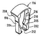
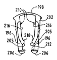
主「馬てい」形リテーナ116が、図25〜図27に詳細に示されている。それは好ましくは、プラスチックなどの弾性的な可撓性材料で成形される。主リテーナ116は、リテーナハウジング部分132の上部スロット158を通って延出して、コネクタ本体112に離脱可能に結合される。   The main “horsebed” retainer 116 is shown in detail in FIGS. It is preferably molded from an elastic flexible material such as plastic. The main retainer 116 extends through the upper slot 158 of the retainer housing portion 132 and is releasably coupled to the connector body 112.

主リテーナ116には、横部材198から延出して、一端部でそれに接合されている1対の細長い略平行脚部196が設けられている。横部材198は、オス部材114の非アップセット外径にほぼ等しい離隔距離を脚部196間に設ける。脚部196は、上部スロット158の軸方向幅にほぼ等しいが、(隙間を与えるために)わずかに小さい軸方向幅を有する。脚部196の横幅は、上部スロット158の横幅より相当に狭く、それにより、(オス部材を挿抜するために)脚部196を外向きに拡開できるようにしている。   The main retainer 116 is provided with a pair of elongated, substantially parallel legs 196 that extend from the transverse member 198 and are joined to it at one end. The transverse member 198 provides a separation distance between the legs 196 that is approximately equal to the non-upset outer diameter of the male member 114. The legs 196 are approximately equal to the axial width of the upper slot 158 but have a slightly smaller axial width (to provide clearance). The lateral width of the leg 196 is considerably narrower than the lateral width of the upper slot 158 so that the leg 196 can be expanded outward (to insert and remove the male member).

横部材198は、脚部196より相当に広い軸方向幅を有する。図26に示されているように、横部材198は、脚部196の外面202と軸方向に整合しているが、脚部196の内面204を軸方向に越えて延出している。   The transverse member 198 has an axial width that is considerably wider than the leg 196. As shown in FIG. 26, the transverse member 198 is axially aligned with the outer surface 202 of the leg 196 but extends beyond the inner surface 204 of the leg 196 in the axial direction.

各脚部196は、横部材198から遠い端部に形成されたラッチ206を有する。主リテーナ116をコネクタ本体112内へ完全に挿入すると、ラッチ206は主リテーナ116をコネクタ本体112に対して所定位置にロックする。ラッチ206によって画定されたラッチ縁部212が、コネクタ本体112の中央支持部材150によって画定されたロック肩部168に係合し、それにより、主リテーナ116を所定位置に解除可能にロックする。各脚部196は、図27に見られる傾斜表面205を有し、これは中央支持部材150の上部横方向外側縁部と相互作用し、それによって主リテーナを上方に押し進める。脚部196の弾性特性が、この関係を確実にする。   Each leg 196 has a latch 206 formed at the end remote from the transverse member 198. When the main retainer 116 is fully inserted into the connector body 112, the latch 206 locks the main retainer 116 in place relative to the connector body 112. A latch edge 212 defined by the latch 206 engages a locking shoulder 168 defined by the central support member 150 of the connector body 112, thereby releasably locking the main retainer 116 in place. Each leg 196 has an inclined surface 205 as seen in FIG. 27, which interacts with the upper lateral outer edge of the central support member 150, thereby pushing the main retainer upward. The elastic properties of the legs 196 ensure this relationship.

解除突出部208が、横部材198のすぐ下側で各脚部196の内面204から突出している。解除突出部208は、横部材198が脚部196から軸方向に延出する距離にほぼ等しい距離だけ、脚部196から軸方向に延出している。図1〜図18の実施形態の主リテーナ16のランプまたはカム面などの、ランプまたはカム面が、各突出部208に形成されている。組み付けられたとき、ランプ面はコネクタ本体112の上部支持部材144の湾曲上面145のすぐ上方に載る。横部材198に圧力を加えて、主リテーナ116をコネクタ本体112内へさらに押し込むと、ランプ面が上部支持部材144を摺動する、すなわち、カム移動する。したがって、脚部196は広がって、ラッチが側部スロット162内で横断方向外向きに移動して、オス部材114を解放することができるようにする。   A release protrusion 208 protrudes from the inner surface 204 of each leg 196 just below the transverse member 198. The release protrusion 208 extends axially from the leg 196 by a distance approximately equal to the distance that the transverse member 198 extends axially from the leg 196. A ramp or cam surface, such as the ramp or cam surface of the main retainer 16 of the embodiment of FIGS. When assembled, the ramp surface rests just above the curved upper surface 145 of the upper support member 144 of the connector body 112. When pressure is applied to the transverse member 198 and the main retainer 116 is further pushed into the connector body 112, the ramp surface slides on the upper support member 144, that is, cams. Accordingly, the legs 196 widen to allow the latch to move laterally outward in the side slot 162 to release the male member 114.

食い付き領域210が、脚部196の前面202に形成されている。これらの領域は、各脚部の前面202から半径方向および軸方向内向きに傾斜して、各脚部の外面202および内面104のほぼ中間で終了する。食い付き領域210間の空間は、外面202付近で最大である。この場合、その空間は、オス部材114に形成されたアップセット190の直径にほぼ等しい。食い付き領域210の内側縁部216において、食い付き領域210間の空間は、オス部材114の(非アップセット)外径にほぼ等しい。食い付き領域210の、ラッチ206により近い部分は218の位置で内向きに湾曲し、それにより、オス部材アップセット190の環状輪郭に一致している。この形状は、コネクタ本体112内を通るオス部材114の案内およびセンタリングを助ける。   A biting area 210 is formed on the front surface 202 of the leg 196. These regions slope radially and axially inward from the front surface 202 of each leg and end approximately halfway between the outer surface 202 and the inner surface 104 of each leg. The space between the biting areas 210 is the maximum near the outer surface 202. In this case, the space is approximately equal to the diameter of the upset 190 formed in the male member 114. At the inner edge 216 of the biting area 210, the space between the biting areas 210 is approximately equal to the (non-upset) outer diameter of the male member 114. The portion of the biting area 210 that is closer to the latch 206 is curved inwardly at the position 218, thereby matching the annular profile of the male member upset 190. This shape helps guide and center the male member 114 through the connector body 112.

オス部材114がコネクタ本体118内に完全に挿入された状態では、チューブアップセット191は、横断方向内壁171の内側のアップセット受け取り室に入っている。主リテーナ116の脚部196は、内面204がアップセット190の半径方向表面191に当接関係にあって、オス部材114がオス受け取り端部128から外向きに軸方向移動するのを阻止するように配置されている。   With the male member 114 fully inserted into the connector body 118, the tube upset 191 is in the upset receiving chamber inside the transverse inner wall 171. The legs 196 of the main retainer 116 are such that the inner surface 204 is in abutting relationship with the radial surface 191 of the upset 190 to prevent the male member 114 from axially moving outwardly from the male receiving end 128. Is arranged.

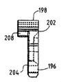
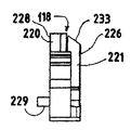
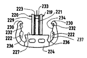
補助ラッチ/確認機構118が、図28〜図30に詳細に示されている。それは、底部スロット166内へ、および側部スロット162内へも挿入されて、コネクタ本体112に離脱可能に結合される。それは、底部支持部材156に対してコネクタ本体112を横切る方向で、湾曲した上部支持部材144に、したがって主リテーナ116に接近およびそれから離れる方向に、内側のラッチ位置と外側のラッチ解除位置との間を摺動可能である。それは好ましくは、プラスチックなどの弾性的な可撓性材料で成形される。   The auxiliary latch / verification mechanism 118 is shown in detail in FIGS. It is also inserted into the bottom slot 166 and also into the side slot 162 and is releasably coupled to the connector body 112. It is between the inner latched position and the outer unlatched position in a direction crossing the connector body 112 relative to the bottom support member 156, in a direction toward and away from the curved upper support member 144, and thus the main retainer 116. Is slidable. It is preferably molded from an elastic flexible material such as plastic.

補助ラッチ/確認機構118は、底部スロット166に重なる半径方向内向きの表面227を有する連結部材224を備え、底部スロット166内に摺動可能に配置されたリテーナビーム219がこの連結部材から延出している。補助ラッチ/確認機構218は、1対の湾曲したほぼ弾性的なフィンガ222の形をした横方向部分も有し、これらは連結部材224から横方向に延出してから、リテーナビーム219と同一方向に内向きに延びている。連結部材の内側横方向延出壁から軸方向内向きにフランジ229が延出している。補助ラッチ/確認機構218がラッチ位置にあるとき、フランジ229は底壁157に比較的近接して重なる。したがって、フランジ229は、ねじ回しの刃または他の器具をフランジ229および底壁157の間に挿入し、それによって補助ラッチ/確認機構218をラッチ解除位置に押し進めることにより、補助ラッチ/確認機構をそのラッチ位置から移動させるのに役立つ。   The auxiliary latch / verifier 118 includes a connecting member 224 having a radially inward surface 227 that overlaps the bottom slot 166 and a retainer beam 219 slidably disposed within the bottom slot 166 extends from the connecting member. ing. The auxiliary latch / verification mechanism 218 also has a lateral portion in the form of a pair of curved, generally elastic fingers 222 that extend laterally from the coupling member 224 and then in the same direction as the retainer beam 219. Extends inward. A flange 229 extends axially inward from the inner lateral extending wall of the connecting member. When the auxiliary latch / verification mechanism 218 is in the latched position, the flange 229 overlaps the bottom wall 157 relatively closely. Thus, the flange 229 inserts a screwdriver blade or other instrument between the flange 229 and the bottom wall 157, thereby pushing the auxiliary latch / verification mechanism 218 to the unlatched position, thereby activating the auxiliary latch / verification mechanism. Helps move from its latched position.

各フィンガ222は、連結部材224から遠い端部に形成されたフック230を有する。補助ラッチ/確認機構がその外側のラッチ解除位置にあるとき、フック224によって画定されたノッチ232が、底部支持部材154によって画定されたロックリッジ172に係合し、それにより、補助ラッチ/確認機構218をコネクタ本体212に取り外し可能に固定する。   Each finger 222 has a hook 230 formed at an end far from the connecting member 224. When the auxiliary latch / verification mechanism is in its outer unlatched position, the notch 232 defined by the hook 224 engages the lock ridge 172 defined by the bottom support member 154, thereby providing an auxiliary latch / verification mechanism. 218 is removably secured to the connector body 212.

フック230および連結部材224間に位置する各フィンガ222の内面は、ランプ面234および横方向拡大表面236の形をとる移行表面と、保持ランド237とを画定する。2つのフィンガ222のランプ面234間の距離は、ロックリッジ172間の距離より短い。横方向拡大表面236間の距離は、ロックリッジ172の横方向外側縁部間の間隔より狭い。2つのフィンガの保持ランド237間の距離は、ロックリッジ172間の距離にほぼ等しい。   The inner surface of each finger 222 located between the hook 230 and the connecting member 224 defines a transition surface in the form of a ramp surface 234 and a laterally enlarged surface 236 and a retaining land 237. The distance between the ramp surfaces 234 of the two fingers 222 is shorter than the distance between the lock ridges 172. The distance between the laterally enlarged surfaces 236 is narrower than the distance between the lateral outer edges of the lock ridge 172. The distance between the two finger holding lands 237 is approximately equal to the distance between the lock ridges 172.

(コネクタ本体の方に向かう)下向きの力を連結部材224に作用することにより、補助ラッチ/確認機構118は、主リテーナ116の方に向かう横断方向にその内側のラッチ位置へ移動する。そのような力は、ロックリッジ172をノッチ232から押し出す。ランプ面234がロックリッジ172の上に載ってフィンガ222を外向きにたわませ、それにより、それらを拡開させて、拡大表面236がロックリッジ172を通過することができ、その時、ロックリッジ172は保持ランド237間に位置する。補助ラッチ/確認機構118は次に、フィンガ222の弾性的特性、および保持ランド237とロックリッジ172との相互作用により、その位置に解放可能に保持される。そのような位置にあるとき、補助ラッチ/確認機構はその「下方」すなわち「ラッチ」位置にある。ねじ回しの刃をフランジ229および底壁157間に挿入して、補助ラッチ/確認機構218をコネクタ本体212の外に押し進めることにより、上述したように、それを取り外してそのラッチ解除位置に移動させることができる。   By applying a downward force (toward the connector body) to the coupling member 224, the auxiliary latch / verification mechanism 118 moves to its inner latching position in a transverse direction toward the main retainer 116. Such a force pushes the lock ridge 172 out of the notch 232. The ramp surface 234 rests on the lock ridge 172 to flex the fingers 222 outward, thereby expanding them, so that the enlarged surface 236 can pass through the lock ridge 172, at which time the lock ridge 172 172 is located between the holding lands 237. The auxiliary latch / verification mechanism 118 is then releasably held in place by the elastic properties of the fingers 222 and the interaction of the holding lands 237 and the lock ridge 172. When in such a position, the auxiliary latch / verification mechanism is in its “down” or “latch” position. Inserting a screwdriver blade between the flange 229 and the bottom wall 157 and pushing the auxiliary latch / verification mechanism 218 out of the connector body 212 removes it and moves it to its unlatched position as described above. be able to.

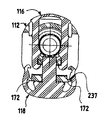
図21に最もわかりやすく見えるように、補助ラッチ/確認機構118がそのラッチ位置にあるとき、フィンガ222の自由端部に位置するフック230は、脚部196の自由端部に位置するラッチ206の横方向外側で側部スロット162内に位置している。フィンガ222上のフック230の内面間の距離は、主リテーナ116のラッチ206の位置における脚部196の外面間の距離よりわずかに長い。フィンガ222の軸方向幅は、脚部196の軸方向幅にほぼ等しい。注目すべきことに、フィンガ222の長さは、補助ラッチ/確認機構218がラッチ位置にあるとき、フィンガ222が脚部196の外向きのたわみを妨害し、それにより、フィンガ196が中央支持部材150のロック肩部168に確実にロックされたままであるようにする長さである。   As can be seen most clearly in FIG. 21, when the auxiliary latch / verifier 118 is in its latched position, the hook 230 located at the free end of the finger 222 has the latch 206 located at the free end of the leg 196. Located laterally outside and in the side slot 162. The distance between the inner surfaces of the hooks 230 on the fingers 222 is slightly longer than the distance between the outer surfaces of the legs 196 at the latch 206 position of the main retainer 116. The axial width of the finger 222 is substantially equal to the axial width of the leg 196. Notably, the length of the finger 222 is such that when the auxiliary latch / verifier 218 is in the latched position, the finger 222 prevents the outward deflection of the leg 196 so that the finger 196 is in the center support member. The length to ensure that it remains locked to the 150 locking shoulders 168.

リテーナビーム219は、横方向拡大部分220および細幅部分221を有する。拡大部分220の横幅は、中央支持部材150の離間壁面167と底部支持部材154の離間壁面169との間の底部スロット166の拡大部分の横幅よりわずかに狭い。細幅部分221の横幅は、横方向に離間した壁175の間の底部スロット166の細幅部分の横幅よりわずかに狭い。   The retainer beam 219 has a laterally enlarged portion 220 and a narrow portion 221. The lateral width of the enlarged portion 220 is slightly narrower than the lateral width of the enlarged portion of the bottom slot 166 between the spaced wall surface 167 of the central support member 150 and the spaced wall surface 169 of the bottom support member 154. The width of the narrow portion 221 is slightly narrower than the width of the narrow portion of the bottom slot 166 between the laterally spaced walls 175.

図28に最もわかりやすく見えるように、リテーナビーム219の断面は「T」字形である。細幅部分221が「T」字形の脚を形成し、拡大部分220が「T」字形の上部の横棒を形成する。リテーナビーム219は拡大部分220上に、コネクタ本体112の底部スロット166の内壁171と向き合う内側または後壁面228を有する。リテーナビームの細幅部分169は、コネクタ本体112の底部スロット166の前壁173と向き合う外側または前壁面226を有する。リテーナビーム219は拡大部分220に、底部支持部材154の壁面169および中央支持部材150の壁面167に対して近接した位置で摺動可能である横方向側壁を有する。図20および図21に最もわかりやすく見えるように、リテーナビーム219の細幅部分221は、底部スロット166の細幅部分の横方向壁175に対して近接した位置で摺動可能である横方向側壁を有する。   As best seen in FIG. 28, the cross section of the retainer beam 219 is “T” shaped. The narrow portion 221 forms a “T” shaped leg, and the enlarged portion 220 forms a “T” shaped upper cross bar. The retainer beam 219 has an inner or rear wall 228 on the enlarged portion 220 that faces the inner wall 171 of the bottom slot 166 of the connector body 112. The narrow portion 169 of the retainer beam has an outer or front wall 226 that faces the front wall 173 of the bottom slot 166 of the connector body 112. The retainer beam 219 has a lateral side wall at the enlarged portion 220 that is slidable at a position proximate to the wall surface 169 of the bottom support member 154 and the wall surface 167 of the center support member 150. As can be seen most clearly in FIGS. 20 and 21, the narrow portion 221 of the retainer beam 219 is slidable in a position proximate to the lateral wall 175 of the narrow portion of the bottom slot 166. Have

したがって、上述したように、補助ラッチ/確認機構118のリテーナビーム219は、コネクタ本体112の底部スロット166内に摺動可能に受け取られて支持される。したがって、補助ラッチ/確認機構118がそのラッチ解除およびラッチ位置間を移動できるように、底部スロット166の壁は、リテーナビーム219を、従って補助ラッチ/確認機構118を底部スロット内に摺動可能に支持する。リテーナビームは、補助ラッチ/確認機構118がラッチ位置にあるとき、貫通内孔126内に露出する長さを有する。   Thus, as described above, the retainer beam 219 of the auxiliary latch / verification mechanism 118 is slidably received and supported within the bottom slot 166 of the connector body 112. Thus, the wall of the bottom slot 166 allows the retainer beam 219 and thus the auxiliary latch / verifier 118 to slide into the bottom slot so that the auxiliary latch / verifier 118 can move between its unlatched and latched positions. To support. The retainer beam has a length that is exposed in the through bore 126 when the auxiliary latch / verifier 118 is in the latched position.

リテーナビーム219の拡大部分220の内壁面228は、当接面を画定する。リテーナビーム219の長さは、補助ラッチ/確認機構118がラッチ位置にあるとき、当接面228がオス部材114のアップセット190の半径方向表面191に当接するように配置されるような長さである。   The inner wall surface 228 of the enlarged portion 220 of the retainer beam 219 defines an abutment surface. The length of the retainer beam 219 is such that the abutment surface 228 is arranged to abut the radial surface 191 of the upset 190 of the male member 114 when the auxiliary latch / verifier 118 is in the latched position. It is.

リテーナビーム118の半径方向内側端部は、オス部材114を形成するチューブの外面195の曲率に一致するように湾曲したチューブ側表面223を画定している。補助ラッチ/確認機構118がラッチ位置にあり、リテーナビーム219の内壁面228がチューブ114の半径方向当接面191に当接した関係にあるとき、チューブ側表面223は、アップセット191の後方でチューブ114の外面195と接近位置で向き合う関係にある。   The radially inner end of the retainer beam 118 defines a tube side surface 223 that is curved to match the curvature of the outer surface 195 of the tube forming the male member 114. When the auxiliary latch / verification mechanism 118 is in the latched position and the inner wall surface 228 of the retainer beam 219 is in contact with the radial contact surface 191 of the tube 114, the tube side surface 223 is behind the upset 191. The outer surface 195 of the tube 114 faces the approaching position.

すなわち、アップセットは、本体112のリテーナ部分132の壁171の軸方向内側にあるコネクタ本体118のアップセット受け取り室内に配置される。脚部196上の内側当接面204は、アップセット190の表面191に当接した関係に配置され、それにより、オス部材190が本体112のオス受け取り端部128から抜けることを阻止する。リテーナビームの内壁面228も同様にアップセット190の半径方向表面191に当接した関係に配置されて、同様にオス部材114の抜けを阻止する。   That is, the upset is disposed in the upset receiving chamber of the connector body 118 that is axially inward of the wall 171 of the retainer portion 132 of the body 112. The inner abutment surface 204 on the leg 196 is disposed in abutting relationship with the surface 191 of the upset 190, thereby preventing the male member 190 from falling out of the male receiving end 128 of the body 112. Similarly, the inner wall surface 228 of the retainer beam is also arranged in contact with the radial surface 191 of the upset 190 to similarly prevent the male member 114 from coming off.

図1〜図18の実施形態に関して図14に示されているように、シール室134内に2つのOリングシールが配置されて、剛性スペーサリングによって分離されている。これらの構成部品の説明を図19〜図30の実施形態では個別に繰り返さないが、等しく適用可能である。第1実施形態の場合のように、Oリングは、シール室134の内側およびオス部材114のシール表面194の周囲に締まりばめされる寸法である。Oリングは、中空のスペーサスリーブによってシール室134内に固定されている。スペーサスリーブには、内壁122の円錐形肩部178に当接し、それにより、スリーブを内孔内に位置決めする円錐形拡大端部が設けられている。スリーブの外周に隆起環状部分が形成されており、内壁122に対応の環状リセス258が形成されている(図23を参照)。スペーサスリーブの隆起部分は、内壁122に形成されたリセス258内にはめ合い状に受け取られ、それによってスリーブを所定位置にロックするであろう。   As shown in FIG. 14 for the embodiment of FIGS. 1-18, two O-ring seals are disposed within the seal chamber 134 and separated by a rigid spacer ring. The description of these components is not repeated individually in the embodiment of FIGS. 19-30, but is equally applicable. As in the case of the first embodiment, the O-ring is dimensioned to be fit inside the seal chamber 134 and around the seal surface 194 of the male member 114. The O-ring is fixed in the seal chamber 134 by a hollow spacer sleeve. The spacer sleeve is provided with a conical enlarged end that abuts the conical shoulder 178 of the inner wall 122, thereby positioning the sleeve within the inner bore. A raised annular portion is formed on the outer periphery of the sleeve, and a corresponding annular recess 258 is formed on the inner wall 122 (see FIG. 23). The raised portion of the spacer sleeve will be received matedly within a recess 258 formed in the inner wall 122, thereby locking the sleeve in place.

本発明によれば、リテーナビーム219の細幅部分221の前方または後向きの表面226は、カムまたはランプ面233によって画定された面取り部分を備える。補助ラッチ/確認機構118をコネクタ本体112に取り付けるとき、カムまたはランプ面233はコネクタ本体118のオス受け取り端部128の方に面する。   In accordance with the present invention, the forward or rearward surface 226 of the narrow portion 221 of the retainer beam 219 comprises a chamfered portion defined by a cam or ramp surface 233. When attaching the auxiliary latch / verification mechanism 118 to the connector body 112, the cam or ramp surface 233 faces the male receiving end 128 of the connector body 118.

補助ラッチ/確認機構118がそのラッチ位置にあるとき、カム面233は、オス部材114の挿入時にアップセット190と接触する位置にある。ランプ面は、リテーナビームを半径方向外向きに押し進める力をリテーナビーム219に加えるような形状になっている。オス部材を挿入すると、リテーナビームが外向きに押し進められて、補助ラッチ/確認機構118がラッチ解除位置に移動する。それから、オス部材114をコネクタ本体112内へ完全に挿入することができる。オス部材114をコネクタ本体内へ完全に挿入した後、補助ラッチ/確認機構118をそのラッチ位置へ半径方向内向きに押し込んで、内面228をアップセット190の半径方向表面191に当接する位置に置く。   When the auxiliary latch / verifier 118 is in its latched position, the cam surface 233 is in contact with the upset 190 when the male member 114 is inserted. The ramp surface is shaped to apply a force to the retainer beam 219 that pushes the retainer beam radially outward. When the male member is inserted, the retainer beam is pushed outward and the auxiliary latch / verification mechanism 118 moves to the unlatched position. The male member 114 can then be fully inserted into the connector body 112. After the male member 114 is fully inserted into the connector body, the auxiliary latch / verifier 118 is pushed radially inward into its latched position to place the inner surface 228 in contact with the radial surface 191 of the upset 190. .

図示の補助ラッチ/確認機構118では、ランプ面233がリテーナビームの前面226に対して60°(度)の角度をなす。ビームを底部スロット166に摺動可能にはめ込むとき、それは中心線または軸124に対してほぼ垂直に位置決めされる。したがって、ランプ面233はコネクタ本体112の軸124に対して約30°の角度をなして、オス受け取り端部128の方に向かって広がっている。   In the illustrated auxiliary latch / verification mechanism 118, the ramp surface 233 makes an angle of 60 ° (degrees) with the front surface 226 of the retainer beam. When the beam is slidably fitted into the bottom slot 166, it is positioned substantially perpendicular to the centerline or axis 124. Accordingly, the ramp surface 233 extends toward the male receiving end 128 at an angle of about 30 ° with respect to the axis 124 of the connector body 112.

カム面に使用される角度は重要ではない。オス部材114の挿入中に加えられる軸方向力が、補助ラッチ/確認機構118をそのラッチ位置からそのラッチ解除位置に並進させるのに十分でありさえすればよい。   The angle used for the cam surface is not critical. The axial force applied during insertion of the male member 114 need only be sufficient to translate the auxiliary latch / verification mechanism 118 from its latched position to its unlatched position.

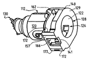
図19〜図30の実施形態の組み付け状態の急速継手が、図19〜図21に最もわかりやすく見える。主リテーナ116をコネクタ本体112に取り付ける。主リテーナ116の脚部196をリテーナハウジング部分132の上部スロット158に通して延出させる。主リテーナ116は、横部材198および解除突出部208が上部支持部材144の湾曲上面145の上方に位置するような向きにされる。脚部196の食い付き領域210がオス部材受け取り端部128と向き合う。   The assembled quick-joint of the embodiment of FIGS. 19-30 appears most clearly in FIGS. The main retainer 116 is attached to the connector main body 112. The legs 196 of the main retainer 116 extend through the upper slot 158 of the retainer housing portion 132. The main retainer 116 is oriented such that the transverse member 198 and the release protrusion 208 are located above the curved upper surface 145 of the upper support member 144. The biting area 210 of the leg 196 faces the male member receiving end 128.

横部材198に下向き力を加えることによって脚部196を上部スロット158に挿入することにより、主リテーナ116がコネクタ本体112に取り付けられる。脚部196が中央支持部材150の側部と接触したとき、下向き力を増加する必要がある。十分な下向き力を加えると、脚部196の丸み付き端部が中央支持部材150の側部を摺動し、脚部196を拡開させて、脚部196が中央支持部材150を通過できるようにする。脚部196上のラッチ206が中央支持部材150を通り過ぎると、脚部196は横方向内向きに跳ねて、ラッチ縁部212が中央支持部材150のロック肩部168の下側に配置され、それにより、主リテーナ116がコネクタ本体112に解除可能にロックされる。   The main retainer 116 is attached to the connector body 112 by inserting a leg 196 into the upper slot 158 by applying a downward force to the transverse member 198. When the leg 196 contacts the side of the central support member 150, the downward force needs to be increased. When a sufficient downward force is applied, the rounded end of the leg 196 slides on the side of the central support member 150 to widen the leg 196 so that the leg 196 can pass through the central support member 150. To. As the latch 206 on the leg 196 passes the central support member 150, the leg 196 springs laterally inward and the latch edge 212 is located under the locking shoulder 168 of the central support member 150, Thus, the main retainer 116 is releasably locked to the connector main body 112.

適切に取り付けられた主リテーナ116が、図20および図21に示されている。取り付け位置では、側部から見たとき、主リテーナ116の脚部196は、内孔126の軸124に対してほぼ垂直である。前方または後方から見たとき、脚部196は内孔126の軸124からほぼ等間隔に位置する。   A properly installed main retainer 116 is shown in FIGS. In the installed position, the leg 196 of the main retainer 116 is substantially perpendicular to the axis 124 of the inner bore 126 when viewed from the side. When viewed from the front or the rear, the legs 196 are located at substantially equal intervals from the shaft 124 of the inner hole 126.

補助ラッチ/確認機構118を底部スロット166にはめ込むことにより、コネクタの組付けが完了する。図19〜図30に示されている本実施形態では、補助ラッチ/確認機構118は、図21に示されているように、ロックリッジ172が保持ランド237の背後に位置した状態で、取り外し可能に位置決めされる。それにより、補助ラッチ/確認機構はその内側のラッチ位置にある。注目すべきことに、そのような位置にあるとき、リテーナビーム219のカム面233は、コネクタ112のオス部材受け取り端部128と向き合い、主リテーナ116の脚部196の傾斜食い付き領域210の中間で貫通穴126内に露出される。   By fitting the auxiliary latch / verification mechanism 118 into the bottom slot 166, the assembly of the connector is completed. In the present embodiment shown in FIGS. 19-30, the auxiliary latch / verification mechanism 118 can be removed with the lock ridge 172 positioned behind the holding land 237 as shown in FIG. Is positioned. Thereby, the auxiliary latch / verification mechanism is in its inner latch position. Notably, when in this position, the cam surface 233 of the retainer beam 219 faces the male member receiving end 128 of the connector 112 and is intermediate the angled biting area 210 of the leg 196 of the main retainer 116. And exposed in the through hole 126.

主リテーナ116および補助ラッチ/確認機構118をコネクタ本体112に取り付けた状態で、オス部材114をコネクタ本体112に挿入し、それにより、流体経路を完成する。オス部材114を挿入するとき、チューブ114の端部または先端192が脚部196の各食い付き傾斜面210と接触する。脚部196間の空間がオス部材114の非アップセット外径にほぼ等しいので、オス部材114のシール表面194は、抵抗をほとんど、またはまったく受けないで、脚部196間を通ってシール室134に入る。   With main retainer 116 and auxiliary latch / verification mechanism 118 attached to connector body 112, male member 114 is inserted into connector body 112, thereby completing the fluid path. When the male member 114 is inserted, the end or tip 192 of the tube 114 comes into contact with each biting inclined surface 210 of the leg 196. Because the space between the legs 196 is approximately equal to the non-upset outer diameter of the male member 114, the sealing surface 194 of the male member 114 passes between the legs 196 with little or no resistance and seal chamber 134. to go into.

オス部材114のアップセット190が脚部196と接触するとき、挿入に対する抵抗が発生する。十分な軸方向内向きの力を加えるときだけ、脚部196の食い付き領域210によってアップセット190が脚部間を通過することができる。アップセット190が脚部196間を通過するとき、それは食い付き領域210に沿って載って、脚部196を半径方向または横方向外向きにたわませる。アップセット190が脚部を通過すると、脚部196はアップセット190の背後でロック位置に跳ね返り、ラッチ縁部112が中央支持部材のロック肩部168に係合する。アップセット191は、リテーナハウジング部分132の壁171と内孔126の円錐形肩部178との間に画定されたアップセット受け取り室内に配置される。脚部196の内面204がアップセットの半径方向表面191に当接し、それにより、後に意図しないでオス部材114がコネクタ本体112から抜けることを防止する。図1〜図18の実施形態に示されているようなスペーサスリーブが、コネクタ本体112の内壁122上に画定された円錐形肩部178と協働して、オス部材114がロック位置からさらに内向きに挿入されることを防止する。   When the upset 190 of the male member 114 contacts the leg 196, resistance to insertion occurs. Only when a sufficient axial inward force is applied, the biting area 210 of the leg 196 allows the upset 190 to pass between the legs. As the upset 190 passes between the legs 196, it rests along the biting area 210, causing the legs 196 to deflect radially or laterally outward. As the upset 190 passes the leg, the leg 196 bounces back to the locked position behind the upset 190 and the latch edge 112 engages the locking shoulder 168 of the central support member. The upset 191 is disposed in an upset receiving chamber defined between the wall 171 of the retainer housing portion 132 and the conical shoulder 178 of the bore 126. The inner surface 204 of the leg 196 abuts against the radial surface 191 of the upset, thereby preventing the male member 114 from falling out of the connector body 112 without intention later. A spacer sleeve as shown in the embodiment of FIGS. 1-18 cooperates with a conical shoulder 178 defined on the inner wall 122 of the connector body 112 so that the male member 114 is further inward from the locked position. Prevent insertion in the direction.

図19ないし図30の実施形態に示されているような本発明の特徴に重要なことに、アップセット190が主リテーナ116の脚部196の傾斜食い付き領域210と接触するとき、それは補助ラッチ/確認機構118のリテーナビーム219のカム面230とも接触する。チューブまたはオス部材114の挿入に向けた継続的な軸方向圧力は、リテーナビーム219にコネクタ本体112から離れる上向きの力を加える。フィンガ222の弾性的な性質により、それらは拡開して、補助ラッチ/確認機構118が底部スロット116内をそのラッチ位置からそのラッチ解除位置へ摺動することができる。横方向拡大表面236がロックリッジ172を通過すると、フィンガ222のランプ面234がロックリッジ172の外縁部と相互作用して、補助ラッチ/確認機構の横断方向外向き移動を容易にする。   Significant to the features of the present invention as shown in the embodiment of FIGS. 19-30, when the upset 190 contacts the beveled area 210 of the leg 196 of the main retainer 116, it is an auxiliary latch. / The cam surface 230 of the retainer beam 219 of the confirmation mechanism 118 also contacts. Continuous axial pressure toward insertion of the tube or male member 114 applies an upward force away from the connector body 112 to the retainer beam 219. Due to the elastic nature of the fingers 222, they expand to allow the auxiliary latch / verifier 118 to slide within the bottom slot 116 from its latched position to its unlatched position. As the laterally enlarged surface 236 passes through the lock ridge 172, the ramp surface 234 of the finger 222 interacts with the outer edge of the lock ridge 172 to facilitate the lateral outward movement of the auxiliary latch / verification mechanism.

ラッチ解除位置では、フィンガ222のフック230のノッチ232が、底部支持部材154のロックリッジ172を捕らえる。この位置で、保持リテーナビーム219の湾曲した当接面223は、軸すなわち中心線124から半径方向外側に間隔をおいて位置し、それにより、チューブアップセット190が通ることができるようになっている。   In the unlatched position, the notch 232 of the hook 230 of the finger 222 catches the lock ridge 172 of the bottom support member 154. In this position, the curved abutment surface 223 of the retaining retainer beam 219 is spaced radially outward from the axis or centerline 124 so that the tube upset 190 can pass therethrough. Yes.

上述したように、チューブアップセット190は、主リテーナ116の脚部196を外向きにたわませて、アップセット190が図1〜図18の実施形態に示されているような内部スペーサスリーブおよび貫通内孔126内の円錐形肩部178と接触することによってさらなる内向き移動が阻止されるまで、中央内孔126内を内向きに通ることができる。そのような位置にあるとき、半径方向に拡大したアップセット190の後側の表面191は、細長い脚部196の後面204の軸方向内側に位置し、その後面はアップセット190の半径方向表面191に当接した関係にある。脚部は、それらの弾性的な特性によって内向きにたわみ、それにより、アップセット191を後面204の内側にロックする。   As described above, the tube upset 190 deflects the legs 196 of the main retainer 116 outward so that the upset 190 is an inner spacer sleeve and the like as shown in the embodiment of FIGS. It can pass inwardly through the central bore 126 until further inward movement is prevented by contact with the conical shoulder 178 in the through bore 126. When in such a position, the radially enlarged rear surface 191 of the upset 190 is located axially inward of the rear surface 204 of the elongated leg 196 and the rear surface is the radial surface 191 of the upset 190. Is in contact with the The legs deflect inward due to their elastic properties, thereby locking the upset 191 inside the rear surface 204.

補助ラッチ/確認機構118がラッチ解除すなわち上方位置にあるとき、横部材198に下向き力を加えることによって、オス部材114を脚部196の背後のロック位置から解放することができる。横部材198に下向き力を加えることにより、解除突出部208のカム面がコネクタ本体112の上部支持部材144の湾曲上面145と接触する。下向きの力を加え続けると、解除突出部208のランプ面が上部支持部材144に接しながら摺動またはカム移動して、脚部196を横方向に拡開させる。最終的に、アップセット190が脚部196間を外向きに通り抜けるようにするのに十分な距離だけ、脚部196が拡開するであろう。これにより、オス部材114をコネクタ本体112から引き抜くことができる。部材114をコネクタ本体112から引き抜いて主リテーナ116が弛緩すると、主リテーナ116はその通常設置位置に戻り、傾斜表面205が中央支持部材150に接して相互作用することによって横部材198が上方へ押し進められる。   The male member 114 can be released from the locked position behind the leg 196 by applying a downward force on the transverse member 198 when the auxiliary latch / verifier 118 is in the unlatched or upper position. By applying a downward force to the lateral member 198, the cam surface of the release protrusion 208 comes into contact with the curved upper surface 145 of the upper support member 144 of the connector main body 112. When the downward force is continuously applied, the ramp surface of the release protrusion 208 slides or cams while contacting the upper support member 144, and the leg 196 is expanded laterally. Eventually, the legs 196 will expand by a distance sufficient to allow the upset 190 to pass outwardly between the legs 196. Thereby, the male member 114 can be pulled out from the connector main body 112. When the member 114 is pulled out of the connector body 112 and the main retainer 116 is relaxed, the main retainer 116 returns to its normal installation position and the inclined surface 205 contacts and interacts with the central support member 150 to push the transverse member 198 upward. It is done.

特に図20および図21を参照しながら、補助ラッチ/確認機構の動作を説明する。両図面において、オス部材114は脚部196の内壁204を軸方向に越えて貫通内孔126内に挿入されている。脚部は、それらのたわんでいない位置に戻った状態に示され、ラッチ縁部112が中央支持部材150のロック肩部168に当接して捕らえられている。上記説明から理解されるように、上述したようなオス部材114の挿入により、補助ラッチ/確認機構118がコネクタ本体112から離れる方向に図20に示されたラッチ解除位置へ上向きに移動する。   The operation of the auxiliary latch / verification mechanism will be described with particular reference to FIGS. In both drawings, the male member 114 is inserted into the through hole 126 beyond the inner wall 204 of the leg 196 in the axial direction. The legs are shown back in their undeflected position, with the latch edge 112 captured against the locking shoulder 168 of the central support member 150. As can be understood from the above description, insertion of the male member 114 as described above causes the auxiliary latch / verification mechanism 118 to move upward to the latch release position shown in FIG.

補助ラッチ/確認機構118をラッチ位置に配置するために、連結部材224に下向き力を加える。十分な下向き力により、フィンガ222のランプ面234がロックリッジ172の側部を摺動して、フィンガ222を拡開させ、フィンガが底部支持部材154を越えて半径方向内向きに進むことができるようにする。図20および図21に示されているように、オス部材114をコネクタ本体112に適切に挿入すると、補助ラッチ/確認機構は、図20に示されたラッチ位置に移動し、その場合、補助ラッチ/確認機構118のフィンガ222の自由端部またはフック230が主リテーナ116の脚部196の横方向外側に位置する。図21に最もわかりやすく見られるように、補助ラッチ/確認機構118がラッチ位置にあるとき、フック230は、主リテーナ116の細長い脚部196の横方向または横断方向外向きのたわみを阻止することができる位置にある。この相互作用は、脚部196を外向きにたわませ、それによってオス部材を貫通内孔126から引き出すことができるようにする横部材198の内向き操作を阻止する。   A downward force is applied to the coupling member 224 to place the auxiliary latch / verification mechanism 118 in the latched position. With sufficient downward force, the ramp surface 234 of the finger 222 slides on the side of the lock ridge 172 to widen the finger 222 and the finger can travel radially inward over the bottom support member 154. Like that. As shown in FIGS. 20 and 21, upon proper insertion of the male member 114 into the connector body 112, the auxiliary latch / verification mechanism moves to the latched position shown in FIG. The free end of the finger 222 or the hook 230 of the confirmation mechanism 118 is located laterally outside the leg 196 of the main retainer 116. As best seen in FIG. 21, when the auxiliary latch / verifier 118 is in the latched position, the hook 230 prevents lateral or transverse outward deflection of the elongated leg 196 of the main retainer 116. Is in a position where This interaction prevents the inward manipulation of the transverse member 198 which allows the leg 196 to deflect outward, thereby allowing the male member to be withdrawn from the through bore 126.

同時に、リテーナビーム219は、オス部材114の方に向けて半径方向内向きに移動する。ラッチ位置では、リテーナビーム219の内壁228は、オス部材114のアップセット190の表面191に軸方向に当接した関係にある。リテーナビーム219およびアップセット190間のこの軸方向当接関係も、オス部材114がチューブ受け取り端部128から軸方向外向きに軸方向移動することを防止して、オス部材114をコネクタ本体112内に保持する補助ラッチ特徴を与える。   At the same time, the retainer beam 219 moves radially inward toward the male member 114. In the latched position, the inner wall 228 of the retainer beam 219 is in contact with the surface 191 of the upset 190 of the male member 114 in the axial direction. This axial contact relationship between the retainer beam 219 and the upset 190 also prevents the male member 114 from axially moving axially outward from the tube receiving end 128, so that the male member 114 is moved into the connector body 112. Auxiliary latch feature to hold on.

図19〜図30の急速継手構造で得られる特定の利点は、コネクタ本体112、主リテーナ116および補助ラッチ/確認機構118を一緒に組み合わせることができ、さらに、補助ラッチ/確認機構118をラッチ位置に配置することができることである。コネクタ本体112および対応の主リテーナ116および補助ラッチ/確認機構118を流体系内に組み込んで、オス部材114を挿入すると、オス部材が補助ラッチ/確認機構をラッチ解除位置に変位させる。オス部材114を貫通内孔126内へ完全に挿入して、半径方向壁191が脚部196の当接内面204の内側にあるようにアップセット190を位置決めすると、補助ラッチ/確認機構118を、チューブ側表面223がチューブ表面195に近接するラッチ位置へ移動させることができ、リテーナビーム219もアップセット190の外向き移動を阻止する位置に置かれる。   A particular advantage obtained with the quick coupling structure of FIGS. 19-30 is that the connector body 112, the main retainer 116 and the auxiliary latch / verification mechanism 118 can be combined together, and further the auxiliary latch / verification mechanism 118 can be It can be arranged in. When connector body 112 and corresponding main retainer 116 and auxiliary latch / verification mechanism 118 are incorporated into the fluid system and male member 114 is inserted, the male member displaces the auxiliary latch / verification mechanism to the unlatched position. When the male member 114 is fully inserted into the through bore 126 and the upset 190 is positioned such that the radial wall 191 is inside the abutting inner surface 204 of the leg 196, the auxiliary latch / verifier 118 is The tube side surface 223 can be moved to a latched position proximate the tube surface 195 and the retainer beam 219 is also positioned to prevent the upset 190 from moving outward.

重要なことに、図1〜図18の実施形態の場合のように、オス部材114が不完全に挿入されている場合、リテーナビーム219の自由端部に位置するチューブ側表面223がアップセット190と接触して、補助ラッチ/確認機構118がラッチ位置に移動するのを阻止する。このように補助ラッチ/確認機構118がラッチ位置へ移動することができないことは、オス部材114の挿入が不完全であって、主リテーナ116の脚部196によって軸方向分離が阻止される固定状態にないことを表すであろう。   Significantly, when the male member 114 is incompletely inserted, such as in the embodiment of FIGS. 1-18, the tube-side surface 223 located at the free end of the retainer beam 219 has an upset 190. To prevent the auxiliary latch / verifier 118 from moving to the latched position. The inability of the auxiliary latch / verification mechanism 118 to move to the latched position in this manner means that the male member 114 is not completely inserted and the axial separation is prevented by the legs 196 of the main retainer 116. It will represent something that is not.

図31〜図34は、本発明の急速継手のさらなる変更形を示す。この実施形態では、図1〜図30の実施形態に関連してすでに説明した特徴を補足するために、外部から見えるさらなるラッチ構造が追加されている。   Figures 31-34 show a further variation of the quick coupling of the present invention. In this embodiment, an additional externally visible latch structure is added to supplement the features already described in connection with the embodiment of FIGS.

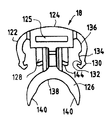
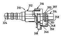
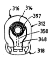
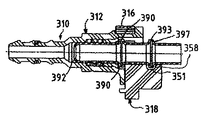
特に図31〜図34を参照すると、取り外し可能な流体接続部においてオス部材314を受け取るメスコネクタ本体312を有する急速継手310が示されている。継手は、主リテーナ316および補助ラッチ/確認機構318を備える。これらの構成部品は、先行の実施形態に関連して説明したように構成されて相互作用する。しかし、本実施形態では、外部から見えるラッチ/確認機構という追加特徴が具現されている。   With particular reference to FIGS. 31-34, a quick coupling 310 is shown having a female connector body 312 that receives a male member 314 at a removable fluid connection. The joint includes a main retainer 316 and an auxiliary latch / verification mechanism 318. These components are configured and interact as described in connection with the previous embodiment. However, in this embodiment, an additional feature of a latch / verification mechanism that is visible from the outside is implemented.

図33に最もわかりやすく見えるように、オス部材314は、図1〜図30の実施形態のオス部材とは幾分異なる。オス部材314は、先端または端部392と、先端から所定距離をおいた位置のアップセット390とを有する。オス部材314はまた、チューブに沿って先端392から離れる方向にアップセット390から所定距離をおいた位置に第2アップセット393を有する。アップセット393は、半径方向環状表面397を有する。   As best seen in FIG. 33, the male member 314 is somewhat different from the male member of the embodiment of FIGS. The male member 314 has a tip or end 392 and an upset 390 at a predetermined distance from the tip. The male member 314 also has a second upset 393 at a predetermined distance from the upset 390 in a direction away from the tip 392 along the tube. Upset 393 has a radial annular surface 397.

オス部材314は、図1〜図30の実施形態に関連して説明されているようにして、メス本体312、主リテーナ316および補助ラッチ/確認機構318と相互作用する。しかし、本実施形態では、チューブ部材314をコネクタ本体312内に完全に挿入して、主リテーナ316および補助ラッチ/確認機構318によって取り外し可能に固定したとき、第2アップセット393がコネクタ本体の外に露出する。   Male member 314 interacts with female body 312, main retainer 316, and auxiliary latch / verification mechanism 318 as described in connection with the embodiment of FIGS. However, in this embodiment, when the tube member 314 is completely inserted into the connector main body 312 and is detachably fixed by the main retainer 316 and the auxiliary latch / confirmation mechanism 318, the second upset 393 is outside the connector main body. Exposed to.

図31〜図34に示されているように、補助ラッチ/確認機構318は、図19〜図30の実施形態に関連して説明した部材のすべてを有する。それはさらに、コネクタ本体312の軸324に平行に前方に延出して横断方向外部ラッチ/確認機構348を支持する前向きの支持バー346を備える。外部ラッチ/確認機構348および支持バー346は、バー345、外部ラッチ/確認機構348および補助ラッチ/確認機構318に一体成形された補強ウェブに接続されている。   As shown in FIGS. 31-34, the auxiliary latch / verification mechanism 318 has all of the members described in connection with the embodiment of FIGS. 19-30. It further comprises a forward-facing support bar 346 that extends forward parallel to the axis 324 of the connector body 312 and supports the transverse external latch / verification mechanism 348. External latch / verification mechanism 348 and support bar 346 are connected to a reinforcing web integrally formed with bar 345, external latch / verification mechanism 348 and auxiliary latch / verification mechanism 318.

図34に示されているように、外部ラッチ/確認機構348は、支持バー346から半径方向に延出して、終端が脚部353を有する横断方向フランジ352になっている。フランジ352は、チューブ312の外側円筒形表面とほぼ同一の曲率を有する内側湾曲面354を有する。脚部353の横断方向外側部分(extent)は、第2アップセット393の外側湾曲面とほぼ同一の曲率を有する短い湾曲セグメント357を有する。   As shown in FIG. 34, the external latch / verification mechanism 348 extends radially from the support bar 346 and ends in a transverse flange 352 having legs 353. The flange 352 has an inner curved surface 354 that has approximately the same curvature as the outer cylindrical surface of the tube 312. The transverse extent of the leg 353 has a short curved segment 357 having a curvature that is substantially the same as the outer curved surface of the second upset 393.

バー346の軸方向長さおよび外部ラッチ/確認機構348の半径方向長さは、補助ラッチ/確認機構318がラッチ位置にあるとき、内側湾曲表面354がオス部材314に第2アップセット393の半径方向表面397の背後または外側と接近位置で向き合う関係にあるようにするものである。フランジは、オス部材314の環状外側半径方向表面397に軸方向に当接する関係に配置された横断方向当接面358を画定する。オス部材314がコネクタ本体312内へ不完全に挿入されて、第1アップセットが主リテーナ316の脚部および補助ラッチ/確認機構318のリテーナビームの内側に捕らえられない場合、短い湾曲セグメント357が第2アップセット393の外周と接触して、適切に接続されていないことを視覚表示する。   The axial length of the bar 346 and the radial length of the external latch / verification mechanism 348 are such that when the auxiliary latch / verification mechanism 318 is in the latched position, the inner curved surface 354 has a radius of the second upset 393 on the male member 314. The directional surface 397 is arranged to face the back or outside of the directional surface 397 at an approach position. The flange defines a transverse abutment surface 358 disposed in axial abutment with the annular outer radial surface 397 of the male member 314. If the male member 314 is incompletely inserted into the connector body 312 and the first upset is not captured inside the leg of the main retainer 316 and the retainer beam of the auxiliary latch / verification mechanism 318, the short curved segment 357 is It contacts the outer periphery of the second upset 393 and visually displays that it is not properly connected.

図33に最もわかりやすく見えるように、ウェブ350には、オス部材またはチューブ314がコネクタ本体312内に完全に挿入された時にウェブ350および第2アップセット393間に隙間を与える切り欠き領域351が設けられている。コネクタ本体312は、ウェブ350の存在に対応して、図1〜図18の実施形態に関連して示したスロット41などの前方スロットを有する。補助ラッチ/確認機構318がそのラッチおよびラッチ解除位置間を移動するのに伴って、ウェブ350はスロット内をコネクタ本体312の内孔の半径方向に摺動可能である。   As can be seen most clearly in FIG. 33, the web 350 has a notch area 351 that provides a gap between the web 350 and the second upset 393 when the male member or tube 314 is fully inserted into the connector body 312. Is provided. The connector body 312 has a forward slot, such as the slot 41 shown in connection with the embodiment of FIGS. As the auxiliary latch / verification mechanism 318 moves between its latched and unlatched positions, the web 350 can slide in the slot in the radial direction of the bore of the connector body 312.

図示して記載した実施形態を参照しながら、本発明のさまざまな特徴を説明してきた。添付の特許請求の範囲によって定義されるような本発明の精神および範囲から逸脱することなく、多くの修正を加えることができることを理解しなければならない。   Various features of the present invention have been described with reference to the illustrated and described embodiments. It should be understood that many modifications can be made without departing from the spirit and scope of the invention as defined by the appended claims.

本発明に従った急速継手の分解図である。FIG. 3 is an exploded view of a quick coupling according to the present invention. 図1のメスコネクタ本体の斜視図である。It is a perspective view of the female connector main body of FIG. 図2のメスコネクタ本体の側面図である。It is a side view of the female connector main body of FIG. 図2のメスコネクタ本体の背面図である。It is a rear view of the female connector main body of FIG. 図4のコネクタ本体の5−5線に沿った断面図である。FIG. 5 is a sectional view taken along line 5-5 of the connector main body of FIG. 図3のコネクタ本体の6−6線に沿った断面図である。FIG. 6 is a cross-sectional view of the connector main body of FIG. 3 taken along line 6-6. 図1の主リテーナの正面図である。It is a front view of the main retainer of FIG. 図7の主リテーナの側面図である。It is a side view of the main retainer of FIG. 図5の主リテーナの背面図である。It is a rear view of the main retainer of FIG. 図1の補助ラッチ/確認機構の斜視図である。FIG. 2 is a perspective view of the auxiliary latch / verification mechanism of FIG. 1. 図10の補助ラッチ/確認機構の上面図である。FIG. 11 is a top view of the auxiliary latch / verification mechanism of FIG. 10. 図10の補助ラッチ/確認機構の背面図である。FIG. 11 is a rear view of the auxiliary latch / verification mechanism of FIG. 10. 図10の補助ラッチ/確認機構の側面図である。FIG. 11 is a side view of the auxiliary latch / verification mechanism of FIG. 10. 図1のコネクタ本体の、シール部材をシール室内に配置した状態での断面図である。It is sectional drawing in the state which has arrange | positioned the sealing member of the connector main body of FIG. 1 in the seal chamber. 図1の継手の、主リテーナがロック位置にあり、補助ラッチ/確認機構がラッチ解除位置にある状態での側面図である。FIG. 2 is a side view of the joint of FIG. 1 with the main retainer in the locked position and the auxiliary latch / verification mechanism in the unlatched position. 図15の継手の、16−16線に沿った断面図である。FIG. 16 is a cross-sectional view of the joint of FIG. 15 taken along line 16-16. 図1の継手の、主リテーナがロック位置にあり、補助ラッチ/確認機構がラッチ位置にある状態での断面図である。2 is a cross-sectional view of the joint of FIG. 1 with the main retainer in the locked position and the auxiliary latch / verification mechanism in the latched position. 図1の継手の、主リテーナがロック解除位置にあり、補助ラッチ/確認機構がラッチ解除位置にある状態での側面図である。FIG. 2 is a side view of the joint of FIG. 1 with the main retainer in the unlocked position and the auxiliary latch / verification mechanism in the latched position. 本発明の特徴を具現し、図1〜図18の実施形態の急速継手と比べて追加能力を有する別の急速継手構造の平面図である。FIG. 19 is a plan view of another quick joint structure embodying features of the present invention and having additional capabilities compared to the quick joint of the embodiment of FIGS. 継手構成部品が流体管路への接続を完了する間の特定の関係にあるところを示す、図19の急速継手の図19の20−20線に沿った断面の平面図である。FIG. 20 is a cross-sectional plan view of the quick coupling of FIG. 19 taken along line 20-20 of FIG. 19 showing the coupling component in a particular relationship while completing the connection to the fluid line. 継手構成部品が流体管路への接続を完了する間の別の関係にあるところを示す、図19の急速継手の図19の20−20線に沿った断面の平面図である。FIG. 20 is a cross-sectional plan view of the quick coupling of FIG. 19 taken along line 20-20 of FIG. 19 showing the coupling component in another relationship while completing the connection to the fluid line. 図19の急速継手のコネクタ本体の斜視図である。It is a perspective view of the connector main body of the quick coupling of FIG. 図19の急速継手のコネクタ本体の断面の側面図である。It is a side view of the cross section of the connector main body of the quick coupling of FIG. 図23のコネクタ本体の、図23の24−24線に沿った断面の平面図である。FIG. 24 is a cross-sectional plan view of the connector body of FIG. 23 taken along line 24-24 of FIG. 図19の急速継手の主リテーナの斜視図である。FIG. 20 is a perspective view of a main retainer of the quick joint of FIG. 19. 図19の急速継手の主リテーナの側面図である。FIG. 20 is a side view of the main retainer of the quick joint of FIG. 19. 図19の急速継手の主リテーナの平面図である。FIG. 20 is a plan view of a main retainer of the quick joint of FIG. 19. 図19の急速継手の補助ラッチ/確認機構の斜視図である。FIG. 20 is a perspective view of the auxiliary latch / verification mechanism of the quick coupler of FIG. 19. 図19の急速継手の補助ラッチ/確認機構の側面図である。FIG. 20 is a side view of the auxiliary latch / verification mechanism of the quick coupler of FIG. 19. 図19の急速継手の補助ラッチ/確認機構の平面図である。FIG. 20 is a plan view of the auxiliary latch / verification mechanism of the quick coupling of FIG. 19. 本発明の原理を具現する急速継手の修正形の側面図である。FIG. 3 is a side view of a modified quick joint embodying the principles of the present invention. 図31の急速継手の端面図である。FIG. 32 is an end view of the quick coupling of FIG. 31. 図31の急速継手の断面の側面図である。FIG. 32 is a side view of a cross section of the quick joint of FIG. 31. 図31の実施形態の補助ラッチ/確認機構の破断図である。FIG. 32 is a cutaway view of the auxiliary latch / verification mechanism of the embodiment of FIG. 31.

Claims (47)

流体管路内で切り離し可能な接続を行うための急速継手であって、
コネクタ本体であって、該コネクタ本体のオス受け取り端部から延在する貫通内孔を画定するコネクタ本体を備え、
該本体は、前記貫通内孔に開いたスロットを有するリテーナハウジング部分を画定し、また、
前記コネクタ本体内に管状オス部材を取り外し可能に固定する主リテーナ部材であって、前記コネクタ本体に取り外し可能に結合され、また、前記本体内のスロット内に互いに間隔をおいて配置された脚部を有し、該脚部は、ロック位置と、前記脚部間の空間が増加するロック解除位置との間を移動可能である、主リテーナ部材と、
前記コネクタ本体に取り外し可能に結合された個別の補助ラッチ/確認機構部材であって、前記本体のスロット内に配置されて、前記コネクタ本体に対して前記主リテーナに接近およびそれから離れる方向に移動してラッチ解除位置およびラッチ位置間を移動可能である個別の補助ラッチ/確認機構部材と、
を備える急速継手。
A quick coupling for making a detachable connection in a fluid line,
A connector body comprising a connector body defining a through bore extending from a male receiving end of the connector body;
The body defines a retainer housing portion having a slot opened in the through bore, and
A main retainer member for removably fixing a tubular male member in the connector body, the leg part being removably coupled to the connector body and spaced from each other in a slot in the body. A main retainer member that is movable between a locked position and an unlocked position in which a space between the legs increases.
A separate auxiliary latch / verification mechanism member removably coupled to the connector body, disposed in a slot of the body, moving toward and away from the main retainer relative to the connector body. Separate auxiliary latch / verification mechanism members movable between the latch release position and the latch position;
Quick fitting with.
前記脚部は、自由端部を有し、前記補助ラッチ/確認機構は、連結部材から延出した1対の弾性フィンガを有する横方向部分を有し、前記フィンガは、前記補助ラッチ/確認機構が前記ラッチ位置にあるとき、前記脚部の前記自由端部の横方向外側に位置する自由端部を有する、請求項1に記載の急速継手。   The leg has a free end, and the auxiliary latch / verification mechanism has a lateral portion having a pair of elastic fingers extending from a connecting member, the finger being the auxiliary latch / verification mechanism. The quick coupling of claim 1, having a free end located laterally outside the free end of the leg when in the latched position. 前記脚部および前記フィンガは、前記補助ラッチ/確認機構が前記ラッチ解除位置にある場合だけ、前記脚部が前記ロック位置から前記ロック解除位置へ移動可能であるようにする寸法である、請求項2に記載の急速継手。   The leg and the finger are dimensioned to allow the leg to move from the locked position to the unlocked position only when the auxiliary latch / verification mechanism is in the unlatched position. 2. The quick coupling according to 2. 前記補助ラッチ/確認機構が前記ラッチ解除位置から前記ラッチ位置に移動するとき、前記脚部が前記ロック解除位置にある場合、前記補助ラッチ/確認機構の前記フィンガは、前記主リテーナの前記脚部の前記自由端部と接触し、該接触により、前記補助ラッチ/確認機構が前記ラッチ位置をとることが防止される、請求項3に記載の急速継手。   When the auxiliary latch / confirmation mechanism moves from the unlatched position to the latched position, the fingers of the auxiliary latch / confirmation mechanism are the legs of the main retainer when the legs are in the unlocked position. 4. A quick coupling as claimed in claim 3 in contact with said free end of said contact, said contact preventing said auxiliary latch / verification mechanism from taking said latch position. 前記脚部は、横部材によって接続されており、また、該横部材を前記コネクタ本体の方に押し付けることにより、前記ロックおよびロック解除位置間を横方向に移動可能である、請求項2に記載の急速継手。   The leg portion is connected by a lateral member, and is movable in the lateral direction between the lock and unlock positions by pressing the lateral member toward the connector body. Quick fittings. 前記コネクタ本体は、上部支持部材、該上部支持部材から間隔をおいた1対の側部支持部材であって、前記上部支持部材および該側部支持部材間に1対の上部スロットを画定する1対の側部支持部材を有し、前記本体はさらに、1対の中央支持部材および1対の底部支持部材を有し、前記中央支持部材および前記底部支持部材は、1対の側部スロットおよび1つの底部スロットを画定し、前記主リテーナの前記横部材は、前記上部支持部材の上に重なり、前記脚部は前記上部スロットを通って延出し、前記脚部の前記自由端部は、前記側部スロット内に露出し、前記補助ラッチ/確認機構の前記連結部材は、前記底部スロットの上に重なって、前記フィンガは前記側部スロットにはまる、請求項5に記載の急速継手。   The connector body is an upper support member, a pair of side support members spaced from the upper support member, and defines a pair of upper slots between the upper support member and the side support members. A pair of side support members, the body further comprising a pair of central support members and a pair of bottom support members, wherein the central support member and the bottom support member comprise a pair of side slots and Defining a bottom slot, the transverse member of the main retainer overlies the upper support member, the leg extends through the upper slot, and the free end of the leg is the 6. A quick coupling as claimed in claim 5, wherein the quick release joint is exposed in a side slot, the connecting member of the auxiliary latch / verification mechanism overlies the bottom slot, and the finger fits in the side slot. 前記底部支持部材は、横方向に向いたロックリッジを有し、前記フィンガの前記自由端部の各々は、ノッチを有するフックを画定し、前記補助ラッチ/確認機構が前記ラッチ解除位置にあるとき、前記ノッチが前記ロックリッジを取り外し可能に受け取る、請求項6に記載の急速継手。   The bottom support member has a laterally oriented lock ridge, each of the free ends of the fingers defines a hook with a notch, and the auxiliary latch / verification mechanism is in the unlatched position The quick coupling of claim 6, wherein the notch removably receives the lock ridge. 前記フィンガは、保持ランドを有し、前記補助ラッチ/確認機構が前記ラッチ位置にあるとき、該保持ランドが前記ロックリッジを受け取る、請求項7に記載の急速継手。   8. The quick coupling of claim 7, wherein the finger has a holding land, and the holding land receives the lock ridge when the auxiliary latch / verification mechanism is in the latched position. 前記フィンガは、前記ノッチおよび前記保持ランド間に移行表面を画定する、請求項8に記載の急速継手。   The quick coupling of claim 8, wherein the finger defines a transition surface between the notch and the retaining land. 前記中央支持部材の各々は、ロック肩部を画定し、前記脚部の前記自由端部の各々は、ラッチを画定し、前記脚部の各々の前記ラッチは、前記主リテーナが前記ロック位置にあるとき、前記中央支持部材の1つのロック肩部に取り外し可能に固定される、請求項9に記載の急速継手。   Each of the central support members defines a locking shoulder, each of the free ends of the legs defines a latch, and each of the latches of the legs has the main retainer in the locked position. 10. The quick coupling of claim 9, wherein at some point, it is removably secured to one locking shoulder of the central support member. 前記補助ラッチ/確認機構は、前記底部スロット内を前記貫通内孔に接近およびそれから離れる方向に摺動可能なリテーナビームをさらに有し、該リテーナビームは、前記補助ラッチ/確認機構が前記ラッチ位置にあるとき、前記貫通内孔内に露出するような長さである、請求項10に記載の急速継手。   The auxiliary latch / confirming mechanism further includes a retainer beam that is slidable in the bottom slot toward and away from the through-bore, the retainer beam including the auxiliary latch / confirming mechanism at the latch position. The quick coupling according to claim 10, wherein the quick coupling has a length so as to be exposed in the through-hole. 前記リテーナビームには、オス部材が前記コネクタ本体内に不完全に挿入されているとき、前記オス部材と接触して、前記補助ラッチ/確認機構が前記ラッチ解除位置から前記ラッチ位置に配置されることを防止する、チューブに面する半径方向内面が設けられる、請求項11に記載の急速継手。   In the retainer beam, when a male member is incompletely inserted into the connector body, the auxiliary latch / confirmation mechanism is disposed from the latch release position to the latch position in contact with the male member. 12. The quick coupling according to claim 11, wherein a radially inner surface facing the tube is provided to prevent this. 前記リテーナビームには、オス部材と軸方向に当接する表面であって、オス部材が前記コネクタ本体内に完全に挿入されたとき、前記オス部材に軸方向に当接する関係に移動可能である表面が設けられる、請求項11に記載の急速継手。   The retainer beam is a surface that contacts the male member in the axial direction, and is a surface that is movable so as to contact the male member in the axial direction when the male member is completely inserted into the connector body. The quick coupling of claim 11, wherein: 前記リテーナビームには、オス部材と軸方向に当接する表面であって、オス部材が前記コネクタ本体内に完全に挿入されたとき、前記オス部材に軸方向に当接する関係に移動可能である表面が設けられる、請求項12に記載の急速継手。   The retainer beam is a surface that contacts the male member in the axial direction, and is a surface that is movable so as to contact the male member in the axial direction when the male member is completely inserted into the connector body. The quick coupling of claim 12, wherein: 前記リテーナビームには、前記コネクタ本体の前記オス部材受け取り端部の方に面して、前記補助ラッチ/確認機構が前記ラッチ位置にあるとき、前記貫通内孔に露出する傾斜ランプ面が設けられる、請求項11に記載の急速継手。   The retainer beam is provided with an inclined ramp surface that faces the male member receiving end of the connector body and is exposed to the through bore when the auxiliary latch / confirmation mechanism is in the latch position. The quick coupling according to claim 11. 前記傾斜ランプ面は、前記コネクタ本体の前記貫通内孔の前記長手軸に対して約30°の角度をなして配置されている、請求項15に記載の急速継手。   The quick coupling according to claim 15, wherein the inclined ramp surface is disposed at an angle of about 30 ° with respect to the longitudinal axis of the through-hole of the connector body. 前記補助ラッチ/確認機構は、前記スロットの1つの内部を前記貫通内孔に接近およびそれから離れる方向に摺動可能なリテーナビームをさらに有し、該リテーナビームは、前記補助ラッチ/確認機構が前記ラッチ位置にあるとき、前記貫通内孔内に露出するような長さである、請求項1に記載の急速継手。   The auxiliary latch / confirming mechanism further includes a retainer beam that is slidable in a direction toward and away from the through-bore inside the one of the slots, and the retainer beam is included in the auxiliary latch / confirming mechanism. The quick coupling according to claim 1, wherein the quick coupling is long enough to be exposed in the through bore when in the latch position. 前記リテーナビームには、オス部材が前記コネクタ本体内に不完全に挿入されているとき、前記オス部材と接触して、前記補助ラッチ/確認機構が前記ラッチ解除位置から前記ラッチ位置に配置されることを防止する、チューブに面する半径方向内側表面が設けられる、請求項17に記載の急速継手。   In the retainer beam, when a male member is incompletely inserted into the connector body, the auxiliary latch / confirmation mechanism is disposed from the latch release position to the latch position in contact with the male member. 18. A quick coupling as claimed in claim 17, wherein a radially inner surface facing the tube is provided to prevent this. 前記リテーナビームには、オス部材と軸方向に当接する表面であって、オス部材が前記コネクタ本体内に完全に挿入されたとき、前記オス部材に軸方向に当接する関係に移動可能である表面が設けられる、請求項17に記載の急速継手。   The retainer beam is a surface that contacts the male member in the axial direction, and is a surface that is movable so as to contact the male member in the axial direction when the male member is completely inserted into the connector body. The quick coupling of claim 17, wherein: 前記リテーナビームには、オス部材と軸方向に当接する表面であって、オス部材が前記コネクタ本体内に完全に挿入されたとき、前記オス部材に軸方向に当接する関係に移動可能である表面が設けられる、請求項18に記載の急速継手。   The retainer beam is a surface that contacts the male member in the axial direction, and is a surface that is movable so as to contact the male member in the axial direction when the male member is completely inserted into the connector body. The quick coupling of claim 18, wherein: 前記リテーナビームには、前記コネクタ本体の前記オス部材受け取り端部の方に面して、前記補助ラッチ/確認機構が前記ラッチ位置にあるとき、前記貫通内孔内に露出する傾斜ランプ面が設けられる、請求項17に記載の急速継手。   The retainer beam is provided with an inclined ramp surface that faces the male member receiving end of the connector body and is exposed in the through hole when the auxiliary latch / confirmation mechanism is in the latch position. 18. The quick coupling according to claim 17, wherein: 前記傾斜ランプ面は、前記コネクタ本体の前記貫通内孔の前記長手軸に対して約30°の角度をなして配置されている、請求項21に記載の急速継手。   24. The quick coupling as claimed in claim 21, wherein the inclined ramp surface is disposed at an angle of about 30 [deg.] With respect to the longitudinal axis of the through bore of the connector body. 前記コネクタ本体によって画定される前記スロットの1つは、断面が「T」字形であり、前記補助ラッチ/確認機構の前記リテーナビームは、断面が「T」字形であり、前記リテーナビームは、そのようなスロット内に摺動可能に支持される、請求項17に記載の急速継手。   One of the slots defined by the connector body is “T” shaped in cross section, the retainer beam of the auxiliary latch / verification mechanism is “T” shaped in cross section, and the retainer beam is 18. A quick coupling as claimed in claim 17 slidably supported in such a slot. 前記リテーナビームは、連結部材から延出し、前記補助ラッチ/確認機構は、前記連結部材から前記リテーナビームと同一方向に延出する1対の弾性フィンガを有する、請求項23に記載の急速継手。   24. The quick coupling of claim 23, wherein the retainer beam extends from a connecting member, and the auxiliary latch / verification mechanism includes a pair of elastic fingers extending from the connecting member in the same direction as the retainer beam. 前記リテーナビームには、前記コネクタ本体の前記オス部材受け取り端部の方に面する傾斜ランプ面が設けられる、請求項24に記載の急速継手。   25. A quick coupling as claimed in claim 24, wherein the retainer beam is provided with an inclined ramp surface facing the male member receiving end of the connector body. 前記傾斜ランプ面は、前記コネクタ本体の前記貫通内孔の前記長手軸に対して約30°の角度をなして配置されている、請求項25に記載の急速継手。   26. The quick coupling as claimed in claim 25, wherein the inclined ramp surface is arranged at an angle of about 30 [deg.] With respect to the longitudinal axis of the through bore of the connector body. 前記補助ラッチ/確認機構は、リムをさらに有し、該リムは、前記補助ラッチ/確認機構を前記コネクタ本体に対して軸方向に位置決めする、請求項1に記載の急速継手。   The quick coupling of claim 1, wherein the auxiliary latch / verification mechanism further comprises a rim, the rim axially positioning the auxiliary latch / verification mechanism relative to the connector body. 前記補助ラッチ/確認機構は、チューブ確認機構を有し、該チューブ確認機構は、前記補助ラッチ/確認機構が前記ラッチ位置にあるとき、前記コネクタ本体の外側で前記オス部材と接近位置で向き合う関係に位置決めされるようにした湾曲面を有する、請求項27に記載の継手。   The auxiliary latch / confirmation mechanism has a tube confirmation mechanism, and the tube confirmation mechanism faces the male member at the approach position outside the connector body when the auxiliary latch / confirmation mechanism is in the latch position. 28. The coupling of claim 27, having a curved surface adapted to be positioned on the surface. 流体管路内で切り離し可能な接続を行うための急速継手であって、
コネクタ本体であって、該コネクタ本体のオス受け取り端部から延在する貫通内孔を画定するコネクタ本体を備え、
該本体は、前記貫通内孔に開いたスロットを有するリテーナハウジング部分を画定し、また、
前記コネクタ本体内に管状オス部材を取り外し可能に固定する主リテーナ部材であって、前記コネクタ本体に取り外し可能に結合され、また、前記本体内のスロット内に互いに間隔をおいて配置された脚部を有し、該脚部は、ロック位置と、前記脚部間の空間が増加するロック解除位置との間を移動可能である、主リテーナ部材と、
前記コネクタ本体に取り外し可能に結合された個別の補助ラッチ/確認機構部材であって、前記コネクタ本体に対してラッチ解除位置からラッチ位置に移動可能であり、前記本体のスロット内に配置されたリテーナビームを有し、該ビームは、該補助ラッチ/確認機構が前記ラッチ位置にあるとき、前記貫通内孔内に露出するような長さを有する、個別の補助ラッチ/確認機構部材と、
を備える急速継手。
A quick coupling for making a detachable connection in a fluid line,
A connector body comprising a connector body defining a through bore extending from a male receiving end of the connector body;
The body defines a retainer housing portion having a slot opened in the through bore, and
A main retainer member for removably fixing a tubular male member in the connector body, the leg part being removably coupled to the connector body and spaced from each other in a slot in the body. A main retainer member that is movable between a locked position and an unlocked position in which a space between the legs increases.
A separate auxiliary latch / verification mechanism member removably coupled to the connector body, the retainer disposed within a slot of the body that is movable relative to the connector body from an unlatched position to a latched position. A separate auxiliary latch / confirmation mechanism member having a beam, the beam having a length that is exposed within the through bore when the auxiliary latch / confirmation mechanism is in the latched position;
Quick fitting with.
前記リテーナビームには、オス部材が前記コネクタ本体内に不完全に挿入されているとき、前記オス部材と半径方向に接触して、前記補助ラッチ/確認機構が前記ラッチ解除位置から前記ラッチ位置に配置されることを防止する、半径方向内側に面する表面が設けられる、請求項29に記載の急速継手。   When the male member is incompletely inserted into the connector main body, the retainer beam contacts the male member in the radial direction, and the auxiliary latch / confirmation mechanism moves from the latch release position to the latch position. 30. The quick coupling as claimed in claim 29, wherein a radially inward facing surface is provided that prevents it from being positioned. 前記リテーナビームには、軸方向に当接する表面であって、オス部材が前記コネクタ本体内に完全に挿入されたとき、前記オス部材に軸方向に当接する関係に移動可能である表面が設けられる、請求項30に記載の急速継手。   The retainer beam is provided with a surface that abuts in the axial direction and is movable so as to abut against the male member in the axial direction when the male member is completely inserted into the connector body. A quick coupling as claimed in claim 30. 前記主リテーナの前記脚部は、前記管状部材が前記貫通内孔内に完全に挿入されたとき、前記アップセットに軸方向に当接する表面を有する、請求項31に記載の急速継手。   32. The quick coupling of claim 31, wherein the leg of the main retainer has a surface that abuts the upset in an axial direction when the tubular member is fully inserted into the through bore. 前記リテーナビームには、前記コネクタ本体の前記オス部材受け取り端部の方に面して、前記補助ラッチ/確認機構が前記ラッチ位置にあるとき、前記貫通内孔内に露出する傾斜ランプ面が設けられる、請求項29に記載の急速継手。   The retainer beam is provided with an inclined ramp surface that faces the male member receiving end of the connector body and is exposed in the through hole when the auxiliary latch / confirmation mechanism is in the latch position. 30. The quick coupling of claim 29. 前記傾斜ランプ面は、前記コネクタ本体の前記貫通内孔の前記長手軸に対して約30°の角度をなして配置されている、請求項33に記載の急速継手。   34. The quick coupling as claimed in claim 33, wherein the inclined ramp surface is disposed at an angle of about 30 degrees with respect to the longitudinal axis of the through bore of the connector body. 前記コネクタ本体によって画定される前記スロットの1つは、断面が「T」字形であり、前記補助ラッチ/確認機構の前記リテーナビームは、断面が「T」字形であり、前記リテーナビームは、そのようなスロット内に摺動可能に支持される、請求項29に記載の急速継手。   One of the slots defined by the connector body is “T” shaped in cross section, the retainer beam of the auxiliary latch / verification mechanism is “T” shaped in cross section, and the retainer beam is 30. A quick coupling as claimed in claim 29, slidably supported in such a slot. 前記リテーナビームは、連結部材から延出し、また、前記連結部材から前記リテーナビームと同一方向に延出する1対の弾性フィンガを有する、請求項29に記載の急速継手。   30. The quick coupling of claim 29, wherein the retainer beam has a pair of resilient fingers extending from a connecting member and extending from the connecting member in the same direction as the retainer beam. 前記コネクタ本体の前記オス受け取り端部内へ、また前記貫通内孔内へ延出するオス部材をさらに備え、該オス部材は、管状表面、および該管状表面より大径の環状アップセットを有し、前記主リテーナの前記脚部は、前記ロック位置にあるとき、前記管状部材を前記コネクタ本体内に取り外し可能に保持する、請求項1に記載の急速継手。   Further comprising a male member extending into the male receiving end of the connector body and into the through bore, the male member having a tubular surface and an annular upset having a larger diameter than the tubular surface; The quick coupling of claim 1, wherein the leg of the main retainer removably retains the tubular member within the connector body when in the locked position. 前記コネクタ本体の前記オス受け取り端部内へ、また前記貫通内孔内へ延出するオス部材をさらに備え、該オス部材は、管状表面、および該管状表面より大径の環状アップセットを有し、前記主リテーナの前記脚部は、前記ロック位置にあるとき、前記管状部材を前記コネクタ本体内に取り外し可能に保持する、請求項6に記載の急速継手。   Further comprising a male member extending into the male receiving end of the connector body and into the through bore, the male member having a tubular surface and an annular upset having a larger diameter than the tubular surface; The quick coupling of claim 6, wherein the leg of the main retainer removably retains the tubular member within the connector body when in the locked position. 前記コネクタ本体の前記オス受け取り端部内へ、また前記貫通内孔内へ延出するオス部材をさらに備え、該オス部材は、管状表面、および該管状表面より大径の環状アップセットを有し、前記主リテーナの前記脚部は、前記ロック位置にあるとき、前記管状部材を前記コネクタ本体内に取り外し可能に保持する、請求項11に記載の急速継手。   Further comprising a male member extending into the male receiving end of the connector body and into the through bore, the male member having a tubular surface and an annular upset having a larger diameter than the tubular surface; The quick coupling of claim 11, wherein the leg of the main retainer removably retains the tubular member within the connector body when in the locked position. 前記コネクタ本体の前記オス受け取り端部内へ、また前記貫通内孔内へ延出するオス部材をさらに備え、該オス部材は、管状表面、および該管状表面より大径の環状アップセットを有し、前記主リテーナの前記脚部は、前記ロック位置にあるとき、前記管状部材を前記コネクタ本体内に取り外し可能に保持する、請求項17に記載の急速継手。   Further comprising a male member extending into the male receiving end of the connector body and into the through bore, the male member having a tubular surface and an annular upset having a larger diameter than the tubular surface; 18. The quick coupling of claim 17, wherein the leg of the main retainer removably retains the tubular member within the connector body when in the locked position. 前記コネクタ本体の前記オス受け取り端部内へ、また前記貫通内孔内へ延出するオス部材をさらに備え、該オス部材は、管状表面、および該管状表面より大径の環状アップセットを有し、前記主リテーナの前記脚部は、前記ロック位置にあるとき、前記管状部材を前記コネクタ本体内に取り外し可能に保持する、請求項25に記載の急速継手。   Further comprising a male member extending into the male receiving end of the connector body and into the through bore, the male member having a tubular surface and an annular upset having a larger diameter than the tubular surface; 26. A quick coupling as claimed in claim 25, wherein the leg of the main retainer removably retains the tubular member within the connector body when in the locked position. 前記コネクタ本体の前記オス受け取り端部内へ、また前記貫通内孔内へ延出するオス部材をさらに備え、該オス部材は、管状表面、および該管状表面より大径の環状アップセットを有し、前記主リテーナの前記脚部は、前記ロック位置にあるとき、前記管状部材を前記コネクタ本体内に取り外し可能に保持する、請求項29に記載の急速継手。   Further comprising a male member extending into the male receiving end of the connector body and into the through bore, the male member having a tubular surface and an annular upset having a larger diameter than the tubular surface; 30. A quick coupling as claimed in claim 29, wherein the leg of the main retainer removably retains the tubular member within the connector body when in the locked position. 前記コネクタ本体の前記オス受け取り端部内へ、また前記貫通内孔内へ延出するオス部材をさらに備え、該オス部材は、管状表面、および該管状表面より大径の環状アップセットを有し、前記主リテーナの前記脚部は、前記ロック位置にあるとき、前記管状部材を前記コネクタ本体内に取り外し可能に保持する、請求項33に記載の急速継手。   Further comprising a male member extending into the male receiving end of the connector body and into the through bore, the male member having a tubular surface and an annular upset having a larger diameter than the tubular surface; 34. A quick coupling as claimed in claim 33, wherein the legs of the main retainer removably retain the tubular member within the connector body when in the locked position. 前記管状オス部材は、前記第1アップセットから間隔をおいた位置に第2アップセットを有し、前記オス部材が前記貫通内孔内に完全に挿入されたとき、該第2アップセットは前記コネクタ本体の前記オス部材受け取り端部の外に露出し、また、前記補助ラッチ確認機構は、内側湾曲面を有する横断方向フランジを有し、該表面は、前記環状オス部材が前記貫通内孔内に完全に挿入されて、前記補助ラッチ/確認機構が前記ラッチ位置にある場合だけ、前記管状オス部材と接近位置で向き合う関係に配置可能であり、前記横断方向フランジは、前記補助ラッチ/確認機構が前記ラッチ位置にあるとき、前記第2アップセットに軸方向に当接する表面を有する、請求項37に記載の急速継手。   The tubular male member has a second upset at a position spaced from the first upset, and when the male member is completely inserted into the through bore, the second upset is The auxiliary body is exposed to the outside of the male member receiving end of the connector body, and the auxiliary latch confirmation mechanism has a transverse flange having an inner curved surface, and the surface has the annular male member in the through-hole. Only when the auxiliary latch / confirmation mechanism is in the latched position and can be placed in an opposed relationship with the tubular male member in the approached position, and the transverse flange includes the auxiliary latch / confirmation mechanism 38. The quick coupling of claim 37, having a surface axially abutting the second upset when is in the latched position. 前記主リテーナの前記脚部は、前記管状部材が前記貫通内孔内に完全に挿入されたとき、前記アップセットに軸方向に当接する表面を有する、請求項37に記載の急速継手。   38. A quick coupling as claimed in claim 37, wherein the leg of the main retainer has a surface that abuts the upset in an axial direction when the tubular member is fully inserted into the through bore. 前記主リテーナの前記脚部は、前記管状部材が前記貫通内孔内に完全に挿入されたとき、前記アップセットに軸方向に当接する表面を有する、請求項38に記載の急速継手。   39. A quick coupling as claimed in claim 38, wherein the leg of the main retainer has a surface that abuts the upset in an axial direction when the tubular member is fully inserted into the through bore. 前記主リテーナの前記脚部は、前記管状部材が前記貫通内孔内に完全に挿入されたとき、前記アップセットに軸方向に当接する表面を有する、請求項42に記載の急速継手。
43. A quick coupling as claimed in claim 42, wherein the legs of the main retainer have surfaces that abut axially against the upset when the tubular member is fully inserted into the through bore.
JP2005100962A 2004-03-31 2005-03-31 Auxiliary latch / checking mechanism for quick joints Expired - Fee Related JP5025091B2 (en)

Applications Claiming Priority (4)

Application Number Priority Date Filing Date Title
US81431404A 2004-03-31 2004-03-31
US10/814314 2004-03-31
US11/087,358 US7390025B2 (en) 2004-03-31 2005-03-23 Secondary latch/verifier for a quick connector
US11/087358 2005-03-23

Publications (3)

Publication Number Publication Date
JP2005291497A true JP2005291497A (en) 2005-10-20
JP2005291497A5 JP2005291497A5 (en) 2008-05-15
JP5025091B2 JP5025091B2 (en) 2012-09-12

Family

ID=34890108

Family Applications (1)

Application Number Title Priority Date Filing Date
JP2005100962A Expired - Fee Related JP5025091B2 (en) 2004-03-31 2005-03-31 Auxiliary latch / checking mechanism for quick joints

Country Status (9)

Country Link
US (1) US7390025B2 (en)
EP (1) EP1582800B1 (en)
JP (1) JP5025091B2 (en)
KR (1) KR101153635B1 (en)
CN (1) CN100489364C (en)
AT (1) ATE363046T1 (en)
BR (1) BRPI0501177B1 (en)
DE (1) DE602005001166T2 (en)
ES (1) ES2285629T3 (en)

Cited By (2)

* Cited by examiner, † Cited by third party
Publication number Priority date Publication date Assignee Title
JP2010509553A (en) * 2006-11-15 2010-03-25 レグリ ソシエテ パ アクシオンス シンプリフィエ Quick connector
JP2016130582A (en) * 2015-01-14 2016-07-21 ノーマ ユー.エス.ホールディング リミティド ライアビリティ カンパニー Conduit connector with first and second latches

Families Citing this family (62)

* Cited by examiner, † Cited by third party
Publication number Priority date Publication date Assignee Title
DE102004020505B4 (en) * 2004-04-22 2009-05-28 A. Raymond Et Cie Coupling for a fluid line system
DE102004038912B3 (en) * 2004-08-11 2005-06-02 A. Raymond & Cie Coupling for connecting two components has receiving part and securing part with locking device to ensure proper insertion of insertion part
DE102004062207B3 (en) * 2004-12-23 2005-10-20 Kirchner Fraenk Rohr Connecting device for connecting up pipelines has locking element with first spring arm carrying holding sector
US7484774B2 (en) * 2005-05-03 2009-02-03 Ti Group Automotive Systems, Llc Redundant latch/verifier for a quick connector
JP5038152B2 (en) * 2005-12-06 2012-10-03 東海ゴム工業株式会社 Quick connector and checker
BRPI0505733A (en) * 2005-12-19 2007-09-25 Click Automotiva Ind Ltda compact connector
US7503784B2 (en) 2006-03-08 2009-03-17 Ti Group Automotive Systems, Llc Quick connector
DE102006019257B4 (en) 2006-04-26 2010-08-05 A. Raymond Et Cie Fluid line coupling
FR2900456B1 (en) * 2006-04-28 2008-06-27 Legris Sa DOUBLE LOCK CONNECTOR
US7866711B2 (en) * 2006-08-22 2011-01-11 Ti Group Automotive Systems, Llc Quick connector with conductive path
DE102006047267B4 (en) * 2006-10-04 2010-02-04 A. Raymond Et Cie Coupling part for a fluid line coupling
DE102008013157A1 (en) * 2008-03-07 2009-09-10 Bayerische Motoren Werke Aktiengesellschaft Hose connector for fixing hose on connecting piece, has securing shanks that are axially deformed, where ends of shanks are radially and inwardly deformed, and deformed sections of shanks lie on outer side of hose at obstructed condition
GB2460641B (en) * 2008-06-02 2013-03-13 Joy Mm Delaware Inc A clip for pin retention
KR101502121B1 (en) * 2008-07-04 2015-03-11 코웨이 주식회사 Insertion assembly for water tank
US8240716B2 (en) 2008-08-07 2012-08-14 TI Group Automotive System, LLC Quick connector coupling with pull tab verifier
US20100052315A1 (en) * 2008-08-28 2010-03-04 Ti Group Automotive Systems, Llc Quick connector coupling with lateral stabilization
FR2945100A1 (en) * 2009-04-30 2010-11-05 Hutchinson CONNECTING CONNECTION BETWEEN A FLUID CONDUIT AND A RIGID BIT WITH A WIRELESS CONNECTION DEVICE AND A METHOD OF CONTROLLING THE CONNECTION
US9464743B2 (en) * 2009-10-21 2016-10-11 Brass-Craft Manufacturing Company Bias release cartridge
US9506592B2 (en) 2009-10-21 2016-11-29 Brass-Craft Manufacturing Company Supply stop with connection verification
US9523454B2 (en) * 2009-10-21 2016-12-20 Brasscraft Manufacturing Company Anti-rotation gripper ring
US9494268B2 (en) * 2009-10-21 2016-11-15 Brasscraft Manufacturing Company Supply stop with connection verification
US20120247179A1 (en) 2011-04-01 2012-10-04 Ti Group Automotive Systems, Llc Sensor housing and latching mechanism for sensor housing
EP2722574B1 (en) * 2011-06-16 2017-08-30 Togo Seisakusyo Corporation Pipe connector
US20130106097A1 (en) * 2011-10-26 2013-05-02 Kil Jae KIM Structure for fastening outlet module of water purifier
US8764068B2 (en) 2012-05-10 2014-07-01 Moen Incorporated Quick connect coupling with retention feature
CN102997031A (en) * 2012-12-13 2013-03-27 苏州和林精密科技有限公司 Bayonet structure for preventing products from interlocking
JP5878457B2 (en) 2012-12-13 2016-03-08 株式会社東海理化電機製作所 Charging cable lock device
EP2796758B1 (en) * 2013-04-23 2016-12-07 TI Automotive (Fuldabrück) GmbH Coupling
CN103939687B (en) * 2014-04-29 2016-08-24 淮南矿业(集团)有限责任公司 hydraulic pipeline connecting device
CN110778818A (en) * 2014-10-09 2020-02-11 可得制品公司 Coupling assembly with retention clip member
EP3275476B1 (en) * 2015-03-23 2020-03-18 JMS Co., Ltd. Adapter
DE102015104889A1 (en) * 2015-03-30 2016-10-06 Voss Automotive Gmbh Connector for media cables with secondary locking
FR3044070B1 (en) 2015-11-20 2019-06-28 A Raymond Et Cie SAFETY TUBULAR CONNECTION WITH AUTOMATIC CONNECTION
US10550982B2 (en) * 2016-06-17 2020-02-04 Ti Group Automotive Systems, Llc Quick connector
US10378686B2 (en) * 2016-07-08 2019-08-13 Hanon Systems Plastic seal fitting
US10627032B2 (en) * 2016-07-22 2020-04-21 Ppi Xiamen Industry Co., Ltd. Quick connection structure of faucet outlet pipe
JP6535422B2 (en) * 2016-10-27 2019-07-03 八千代工業株式会社 Mounting structure for internal parts of fuel tank
CN106352182B (en) * 2016-11-23 2017-12-19 黄松檀 A kind of pipeline connector applied to intelligent automobile
US20180202592A1 (en) * 2017-01-19 2018-07-19 Air International (Us) Inc. Quick connect assembly
US10816121B2 (en) * 2017-05-09 2020-10-27 Martinrea International US Inc. Quick connect coupling with verifier
USD859618S1 (en) 2017-09-15 2019-09-10 Pentair Water Pool And Spa, Inc. Heating apparatus clip
US11199281B2 (en) 2018-01-31 2021-12-14 A. Raymond Et Cie. Dual-latch quick connector
JP6722714B2 (en) * 2018-04-26 2020-07-15 住友理工株式会社 Quick connector
CN108571631B (en) * 2018-06-15 2024-03-29 廊坊舒畅汽车零部件有限公司 Quick connector
FR3083290B1 (en) * 2018-06-29 2021-12-24 Sogefi Air & Cooling QUICK CONNECTION SYSTEM AND METHOD OF REALIZATION
CN110768064B (en) * 2018-07-25 2022-02-08 台达电子工业股份有限公司 Power outlet
US11560967B2 (en) 2018-09-04 2023-01-24 Brasscraft Manufacturing Company Rotation-resistant push-on conduit coupling cartridge
FR3086721B1 (en) * 2018-09-28 2020-11-20 Hutchinson FLUID CONNECTION DEVICE FOR A MOTOR VEHICLE FLUID CIRCUIT
EP3736481B1 (en) 2019-05-07 2022-01-19 A. Raymond et Cie Quick connector assembly with verification tab
CN110626502B (en) * 2019-10-28 2025-01-24 深圳市道通智能航空技术股份有限公司 A quick-detachable structure and aircraft
US11262008B2 (en) * 2020-03-12 2022-03-01 Ti Group Automotive Systems, Llc Transmitter for quick connector
DE112021002981T5 (en) 2020-05-26 2023-03-09 Dlhbowles, Inc. QUICK CONNECTORS FOR FLUID LINES WITH POSITIVE CONFIRMATION FUNCTION
CN111720646A (en) * 2020-06-28 2020-09-29 浙江波士特机械有限公司 Commercial car pneumatic braking system is with inserting connector soon
US11982382B2 (en) * 2021-02-22 2024-05-14 Cooper-Standard Automotive Inc. Quick connector with bracket retainer
US11598463B2 (en) * 2021-03-18 2023-03-07 Ti Group Automotive Systems, Llc Quick connector with verification
CN117836551A (en) 2021-08-13 2024-04-05 Dlh鲍尔斯公司 Automobile industry association connector assembly with verification function
US12281738B2 (en) * 2021-08-18 2025-04-22 Cooper-Standard Automotive Inc. Quick connector with verifier
CN114110280A (en) * 2021-11-05 2022-03-01 重庆溯联塑胶股份有限公司 Be used for two-way quick cut-off connecting device of new forms of energy pipe-line system
US11525428B1 (en) * 2021-12-06 2022-12-13 Robert Bosch Gmbh Retaining clip and connection assembly including same
CN117386910A (en) * 2022-07-12 2024-01-12 伊利诺斯工具制品有限公司 Female connector and connector assembly comprising same
US12104729B2 (en) 2022-08-30 2024-10-01 A. Raymond Et Cie Quick connector verification system and related method of use
DE102022126011A1 (en) * 2022-10-07 2024-04-18 Norma Germany Gmbh Connection system for conducting fluid

Citations (4)

* Cited by examiner, † Cited by third party
Publication number Priority date Publication date Assignee Title
US5401063A (en) * 1993-07-19 1995-03-28 Enhanced Applications, L.C. Primary/secondary retainer for beaded/flared tubing
US5782502A (en) * 1995-12-29 1998-07-21 Itt Automotive, Inc. Radial-release quick connector
JP2004003635A (en) * 2002-05-04 2004-01-08 Ti Automotive (Fuldabrueck) Gmbh Pipe joint for piping
JP2004060884A (en) * 2002-06-04 2004-02-26 Piolax Inc Connector with check function built therein

Family Cites Families (15)

* Cited by examiner, † Cited by third party
Publication number Priority date Publication date Assignee Title
US4948175A (en) 1980-10-29 1990-08-14 Proprietary Technology, Inc. Swivelable quick connector assembly
JPH0538317Y2 (en) * 1988-03-03 1993-09-28
US4869534A (en) * 1988-09-26 1989-09-26 Huron Products Corporation Swivelable quick connector
US5423577A (en) 1992-01-17 1995-06-13 Bundy Corporation Tubing connector
TW302063U (en) 1992-09-24 1997-04-01 Honda Motor Co Ltd Pipe joint
US5395140A (en) 1993-05-13 1995-03-07 Enhanced Applications, L.C. Secondary latch and indicator for fluid coupling
US5586792A (en) * 1995-02-21 1996-12-24 Bundy Corporation Quick connector with integral release mechanism
US5628531A (en) 1995-04-26 1997-05-13 Bundy Corporation Quick connector with secondary latch
ATE200145T1 (en) * 1995-05-17 2001-04-15 Showa Aluminum Corp PIPE CONNECTION
BR9601539A (en) 1996-04-12 2004-06-29 Tampas Click Ltda Mounting and connecting indicator for fuel or general fluid lines
US5897145A (en) 1996-12-05 1999-04-27 Tokai Rubber Industries, Ltd. Connector
US5863077A (en) 1996-12-20 1999-01-26 Itt Automotive, Inc. Quick connector with snap-on frangible retainer
DE19708377C1 (en) 1997-03-01 1998-06-18 Raymond A & Cie Detachable plug-in connector for gas and liquid pipes
DE19822574C1 (en) * 1998-05-20 1999-10-14 Raymond A & Cie Fuel line quick coupling for motor vehicle
US6905143B2 (en) 2002-03-22 2005-06-14 Itt Manufacturing Enterprises, Inc. Fluid conduit quick connector and stuffer pack

Patent Citations (4)

* Cited by examiner, † Cited by third party
Publication number Priority date Publication date Assignee Title
US5401063A (en) * 1993-07-19 1995-03-28 Enhanced Applications, L.C. Primary/secondary retainer for beaded/flared tubing
US5782502A (en) * 1995-12-29 1998-07-21 Itt Automotive, Inc. Radial-release quick connector
JP2004003635A (en) * 2002-05-04 2004-01-08 Ti Automotive (Fuldabrueck) Gmbh Pipe joint for piping
JP2004060884A (en) * 2002-06-04 2004-02-26 Piolax Inc Connector with check function built therein

Cited By (2)

* Cited by examiner, † Cited by third party
Publication number Priority date Publication date Assignee Title
JP2010509553A (en) * 2006-11-15 2010-03-25 レグリ ソシエテ パ アクシオンス シンプリフィエ Quick connector
JP2016130582A (en) * 2015-01-14 2016-07-21 ノーマ ユー.エス.ホールディング リミティド ライアビリティ カンパニー Conduit connector with first and second latches

Also Published As

Publication number Publication date
ES2285629T3 (en) 2007-11-16
ATE363046T1 (en) 2007-06-15
CN1676982A (en) 2005-10-05
KR101153635B1 (en) 2012-06-18
CN100489364C (en) 2009-05-20
US7390025B2 (en) 2008-06-24
US20050218650A1 (en) 2005-10-06
JP5025091B2 (en) 2012-09-12
DE602005001166T2 (en) 2008-01-24
KR20060045386A (en) 2006-05-17
EP1582800B1 (en) 2007-05-23
BRPI0501177A (en) 2005-11-08
BRPI0501177B1 (en) 2018-08-07
DE602005001166D1 (en) 2007-07-05
EP1582800A1 (en) 2005-10-05

Similar Documents

Publication Publication Date Title
JP5025091B2 (en) Auxiliary latch / checking mechanism for quick joints
JP2005291497A5 (en)
JP5054930B2 (en) Redundant latch / check mechanism for quick couplings
JP5464940B2 (en) Quick connector fitting with pull tab retainer
US7128347B2 (en) Passive transmitter for a quick connector
JP6816956B2 (en) Conduit connector with first and second latches
JP5301789B2 (en) Hybrid quick joint
CN209084244U (en) Connector assembly
JP7690599B2 (en) Verification-enabled quick connector
US5586792A (en) Quick connector with integral release mechanism
EP1909016B1 (en) Quick connector coupling
US6757950B2 (en) Rotatable quick connector stuffer pin
JP2009270718A (en) Quick connector, release tool, and method therefor
JP2003120879A (en) Fluid quick connector having end form furnished with groove
CN114593294A (en) Connector with Guided Pilot
EP4372262A1 (en) Connector with guiding components
US12000513B2 (en) Quick connector assembly for fluid lines with positive assurance feature
EP1719944B2 (en) A quick connector
KR200497939Y1 (en) Quick connector with verifier mechanism
JP2006132763A (en) Fluid quick connector with slidable retainer
US20060087118A1 (en) Fluid quick connector with adapter
RU2697280C2 (en) Pipeline connector (embodiments)

Legal Events

Date Code Title Description
A521 Request for written amendment filed

Free format text: JAPANESE INTERMEDIATE CODE: A523

Effective date: 20080331

A621 Written request for application examination

Free format text: JAPANESE INTERMEDIATE CODE: A621

Effective date: 20080331

A131 Notification of reasons for refusal

Free format text: JAPANESE INTERMEDIATE CODE: A131

Effective date: 20110202

A601 Written request for extension of time

Free format text: JAPANESE INTERMEDIATE CODE: A601

Effective date: 20110502

A602 Written permission of extension of time

Free format text: JAPANESE INTERMEDIATE CODE: A602

Effective date: 20110510

A521 Request for written amendment filed

Free format text: JAPANESE INTERMEDIATE CODE: A523

Effective date: 20110729

A131 Notification of reasons for refusal

Free format text: JAPANESE INTERMEDIATE CODE: A131

Effective date: 20120130

A521 Request for written amendment filed

Free format text: JAPANESE INTERMEDIATE CODE: A523

Effective date: 20120418

TRDD Decision of grant or rejection written
A01 Written decision to grant a patent or to grant a registration (utility model)

Free format text: JAPANESE INTERMEDIATE CODE: A01

Effective date: 20120521

A01 Written decision to grant a patent or to grant a registration (utility model)

Free format text: JAPANESE INTERMEDIATE CODE: A01

A61 First payment of annual fees (during grant procedure)

Free format text: JAPANESE INTERMEDIATE CODE: A61

Effective date: 20120619

FPAY Renewal fee payment (event date is renewal date of database)

Free format text: PAYMENT UNTIL: 20150629

Year of fee payment: 3

R150 Certificate of patent or registration of utility model

Ref document number: 5025091

Country of ref document: JP

Free format text: JAPANESE INTERMEDIATE CODE: R150

Free format text: JAPANESE INTERMEDIATE CODE: R150

R250 Receipt of annual fees

Free format text: JAPANESE INTERMEDIATE CODE: R250

R250 Receipt of annual fees

Free format text: JAPANESE INTERMEDIATE CODE: R250

R250 Receipt of annual fees

Free format text: JAPANESE INTERMEDIATE CODE: R250

R250 Receipt of annual fees

Free format text: JAPANESE INTERMEDIATE CODE: R250

R250 Receipt of annual fees

Free format text: JAPANESE INTERMEDIATE CODE: R250

R250 Receipt of annual fees

Free format text: JAPANESE INTERMEDIATE CODE: R250

R250 Receipt of annual fees

Free format text: JAPANESE INTERMEDIATE CODE: R250

R250 Receipt of annual fees

Free format text: JAPANESE INTERMEDIATE CODE: R250

LAPS Cancellation because of no payment of annual fees