JP2005291463A - Hydraulic driving device of hydraulic work machine - Google Patents
Hydraulic driving device of hydraulic work machine Download PDFInfo
- Publication number
- JP2005291463A JP2005291463A JP2004111196A JP2004111196A JP2005291463A JP 2005291463 A JP2005291463 A JP 2005291463A JP 2004111196 A JP2004111196 A JP 2004111196A JP 2004111196 A JP2004111196 A JP 2004111196A JP 2005291463 A JP2005291463 A JP 2005291463A
- Authority
- JP
- Japan
- Prior art keywords
- control valve
- flow rate
- inflow
- command value
- bypass
- Prior art date
- Legal status (The legal status is an assumption and is not a legal conclusion. Google has not performed a legal analysis and makes no representation as to the accuracy of the status listed.)
- Pending
Links
- 230000004044 response Effects 0.000 claims abstract description 133
- 238000012545 processing Methods 0.000 claims abstract description 37
- 239000003921 oil Substances 0.000 claims description 96
- 239000010720 hydraulic oil Substances 0.000 claims description 44
- 238000012937 correction Methods 0.000 claims description 35
- 238000000034 method Methods 0.000 claims description 23
- 230000008569 process Effects 0.000 claims description 23
- 230000007935 neutral effect Effects 0.000 claims description 22
- 230000000630 rising effect Effects 0.000 abstract description 13
- 230000007423 decrease Effects 0.000 description 25
- 238000010586 diagram Methods 0.000 description 17
- 230000003111 delayed effect Effects 0.000 description 14
- 230000006866 deterioration Effects 0.000 description 14
- 230000000694 effects Effects 0.000 description 10
- 230000008859 change Effects 0.000 description 7
- 230000009467 reduction Effects 0.000 description 7
- 230000002265 prevention Effects 0.000 description 6
- 230000008602 contraction Effects 0.000 description 4
- 230000008929 regeneration Effects 0.000 description 4
- 238000011069 regeneration method Methods 0.000 description 4
- 230000003068 static effect Effects 0.000 description 4
- 238000007796 conventional method Methods 0.000 description 2
- 230000001172 regenerating effect Effects 0.000 description 2
- 238000013461 design Methods 0.000 description 1
- 239000012530 fluid Substances 0.000 description 1
- 230000007246 mechanism Effects 0.000 description 1
- 238000006386 neutralization reaction Methods 0.000 description 1
- 230000002093 peripheral effect Effects 0.000 description 1
- 238000005549 size reduction Methods 0.000 description 1
- 239000010902 straw Substances 0.000 description 1
Images


Landscapes
- Operation Control Of Excavators (AREA)
- Fluid-Pressure Circuits (AREA)
Abstract
Description
本発明は、油圧ショベル等の油圧作業機械に備えられ、油圧ポンプから油圧アクチュエータに供給される圧油の流量を制御する流入流量制御弁と、油圧ポンプと流入流量制御弁を接続する供給管路から分岐して作動油タンクに接続されるバイパス管路と、このバイパス管路に設けられ、供給管路から作動油タンクに導かれる圧油の流量を制御するバイパス流量制御弁とを備える油圧作業機械の油圧駆動装置に関する。 The present invention is provided in a hydraulic working machine such as a hydraulic excavator, and includes an inflow flow rate control valve that controls the flow rate of pressure oil supplied from a hydraulic pump to a hydraulic actuator, and a supply line that connects the hydraulic pump and the inflow flow rate control valve. Hydraulic work comprising: a bypass pipe branched from the pipe and connected to the hydraulic oil tank; and a bypass flow control valve provided in the bypass pipe for controlling the flow rate of pressure oil led from the supply pipe to the hydraulic oil tank The present invention relates to a hydraulic drive device for a machine.
従来から、油圧作業機械、例えば油圧ショベルの油圧駆動装置は、油圧ポンプから油圧アクチュエータに供給される圧油の流量を制御する流入流量制御弁と、油圧ポンプと流入流量制御弁を接続する供給管路から分岐して作動油タンクに接続されるバイパス管路と、このバイパス管路に設けられ、供給管路から作動油タンクに導かれる圧油の流量を制御するバイパス流量制御弁とを備えている。このような構成の油圧駆動装置には、次に述べる第1の従来技術および第2の従来技術がある。 Conventionally, a hydraulic drive device for a hydraulic working machine, for example, a hydraulic excavator, includes an inflow flow rate control valve that controls the flow rate of pressure oil supplied from a hydraulic pump to a hydraulic actuator, and a supply pipe that connects the hydraulic pump and the inflow flow rate control valve. A bypass pipe branched from the passage and connected to the hydraulic oil tank, and a bypass flow control valve provided in the bypass pipe and controlling the flow rate of the pressure oil led from the supply pipe to the hydraulic oil tank. Yes. The hydraulic drive apparatus having such a configuration includes a first conventional technique and a second conventional technique described below.
<第1の従来技術>
第1の従来技術では、流入流量制御弁が、中立位置で油圧ポンプと油圧シリンダ(油圧アクチュエータ)との間を遮断するように構成されたクローズドセンタ型の方向切換弁からなる。また、流入流量制御弁およびバイパス流量制御弁は、電磁弁からなる。
<First prior art>
In the first prior art, the inflow flow rate control valve is a closed center type directional control valve configured to shut off between the hydraulic pump and the hydraulic cylinder (hydraulic actuator) in the neutral position. The inflow flow rate control valve and the bypass flow rate control valve are composed of electromagnetic valves.
また、第1従来技術では、流入流量制御弁およびバイパス流量制御弁を制御する制御手段を備えている。この制御手段は、レバー操作により出力される電気信号に応じて流入流量制御弁およびバイパス流量制御弁を駆動させるための電気信号を出力するものである。(特許文献1参照) The first prior art also includes control means for controlling the inflow flow rate control valve and the bypass flow rate control valve. This control means outputs an electrical signal for driving the inflow flow rate control valve and the bypass flow rate control valve in accordance with the electrical signal output by the lever operation. (See Patent Document 1)
<第2の従来技術>
第2の従来技術は、油圧シリンダ(油圧アクチュエータ)に供給される圧油の流れを制御するオープンセンタ型の方向切換弁を有する回路と、流入流量制御弁とバイパス流量制御弁を有し、方向切換弁を介さずにシリンダのボトム側に圧油を供給する回路との2系統の油圧回路を備えている。流入流量制御弁およびバイパス流量制御弁は、電磁比例弁からなる。
<Second prior art>
The second prior art has a circuit having an open center type direction switching valve for controlling the flow of pressure oil supplied to a hydraulic cylinder (hydraulic actuator), an inflow flow rate control valve, and a bypass flow rate control valve. There are two systems of hydraulic circuits including a circuit for supplying pressure oil to the bottom side of the cylinder without using a switching valve. The inflow flow rate control valve and the bypass flow rate control valve are composed of electromagnetic proportional valves.
また、第2の従来技術は、流入流量制御弁およびバイパス流量制御弁を制御する制御手段を備えている。この制御手段は、レバー操作により出力される電気信号に応じて流入流量制御弁およびバイパス流量制御弁を駆動させるための電気信号を出力するものである。(特許文献2参照)
上述した第1従来技術および第2従来技術では、流入流量制御弁の動作とバイパス流量制御弁との動作との協調性の不良によって、供給管路の圧力が急上昇する現象が生じる、すなわち、供給管路内にサージ圧が発生する。このサージ圧の発生は、油圧アクチュエータの操作性の悪化、ポンプ吐出圧の安定性の悪化、騒音の発生、機器の寿命の低下などを招く。 In the first prior art and the second prior art described above, a phenomenon in which the pressure in the supply pipe line rapidly rises due to poor coordination between the operation of the inflow flow control valve and the operation of the bypass flow control valve, that is, the supply Surge pressure is generated in the pipeline. The generation of the surge pressure leads to deterioration of the operability of the hydraulic actuator, deterioration of the stability of the pump discharge pressure, generation of noise, reduction of the life of the equipment, and the like.
ここで、サージ圧が発生するメカニズムについて図9〜11を用いて説明する。 Here, a mechanism for generating the surge pressure will be described with reference to FIGS.
図9は、流入流量制御弁とバイパス流量制御弁とを備えるブリードオフ回路の構成を示す油圧回路図、図10は、流入流量制御弁およびバイパス流量制御弁のそれぞれの開口面積特性の一例を示す特性線図、図11は、流入流量制御弁およびバイパス流量制御弁のそれぞの応答特性の一例を示す特性線図である。 FIG. 9 is a hydraulic circuit diagram showing the configuration of a bleed-off circuit including an inflow flow rate control valve and a bypass flow rate control valve, and FIG. 10 shows an example of each opening area characteristic of the inflow flow rate control valve and the bypass flow rate control valve. FIG. 11 is a characteristic diagram showing an example of response characteristics of the inflow flow rate control valve and the bypass flow rate control valve.
図9に示すように、ブリードオフ回路は、油圧ポンプ1と、この油圧ポンプ1と油圧アクチュエータを接続する供給管路2と、この供給管路2に設けられ、油圧アクチュエータに流入する圧油の流量を制御する流入流量制御弁3と、供給管路2から分岐して作動油タンク6に接続されるバイパス管路4と、このバイパス管路4に設けられ、供給管路2から作動油タンク6にバイパスする圧油の流量を制御するバイパス流量制御弁5と、油圧ポンプ1の吐出圧を制限するリリーフ弁7とを備えている。
As shown in FIG. 9, the bleed-off circuit includes a
流入流量制御弁3は、中立位置が閉位置である中立クローズ型のスプール弁からなり、例えば図10(a)に示すように、スプールのストロークSaの増加に伴って開口面積が増加するようになっている。バイパス流量制御弁5は、中立位置が開位置である中立オープン型のスプール弁からなり、例えば図10(b)に示すように、スプールのストロークScの増加に伴って開口面積が減少するようになっている。流入流量制御弁3とバイパス流量制御弁5とは、流入流量制御弁3におけるストロークSaの変化に対応する開口面積Aaの変化と、バイパス流量制御弁5におけるストロークScの変化に対応する開口面積Acの変化とが、例えば対称になるように設計されているとする。
The inflow flow
流入流量制御弁3では、例えば図11(a)に示すストローク目標指令のステップ入力に対して、同図11(b)に実線で示したストローク応答特性と、同図11(d)に実線で示した開口面積応答特性とが得られる。バイパス流量制御弁5では、同図11(a)に示すストローク目標指令のステップ入力に対して、同図11(c)に実線で示したストローク応答特性と、同図11(e)に実線で示した開口面積応答特性とが得られる。
In the inflow flow
図11(b)〜(e)に実線で示した応答特性は、流入流量制御弁3の開口面積応答特性とバイパス流量制御弁5の開口面積応答特性とが理想的に協調した場合の一例である。この例の場合、流入流量制御弁3とバイパス流量制御弁5のストローク応答特性は同じものになり、流入流量制御弁3の開口面積応答特性とバイパス流量制御弁5の開口面積応答特性とが対称となっている。つまり、流入流量制御弁3の開口面積Aaの増加分と同じ大きさで、バイパス流量制御弁5の開口面積Acが減少していき、流入流量制御弁3の開口面積Aaの減少分と同じ大きさで、バイパス流量制御弁5の開口面積Acが増加するようになっている。
The response characteristics indicated by the solid lines in FIGS. 11B to 11E are examples in which the opening area response characteristics of the inflow flow
このように流入流量制御弁3の開口応答特性とバイパス流量制御弁5の開口応答特性が理想的に協調するものでは、流入流量制御弁3の開口面積Aaとバイパス流量制御弁5の開口面積Acとの合計「Aa+Ac」が、油圧ポンプ1から吐出された圧油を油圧アクチュエータおよび作動油タンク6の少なくとも一方に円滑に導くのに十分な大きさになる。つまり、供給管路2内の圧力が油圧アクチュエータや作動油タンク6に逃げるので、供給管路2内にサージ圧は発生しない。
When the opening response characteristic of the inflow flow
しかし、流入流量制御弁3とバイパス流量制御弁5とは構造が異なる。このため、流入流量制御弁3におけるストロークSaの変化に対応する開口面積Aaの変化と、バイパス流量制御弁5におけるストロークScの変化に対応する開口面積Acの変化とが、上述した図10に示すように対称となるように、流入流量制御弁3とバイパス流量制御弁5とを設計したとしても、流入流量制御弁3およびバイパス流量制御弁5の実際の動作において、流入流量制御弁3のストローク応答特性とバイパス流量制御弁5のストローク応答特性が図11(b)、(c)の実線で示すように同じになるようにするのは困難である。したがって、同図11(d),(e)のように理想的に協調した開口面積特性を得られず、開口面積特性の協調性の不良が生じる。
However, the inflow flow
そして、流入流量制御弁3とバイパス流量制御弁5との開口面積特性に協調性の不良が生じると、流入流量制御弁3の開口面積Aaとバイパス流量制御弁5の開口面積Acとの合計「Aa+Ac」は、油圧ポンプ1から吐出された圧油を油圧アクチュエータや作動油タンク6に円滑に導くには小さすぎる状態となり、これに伴って、供給管路2内の圧力が油圧アクチュエータや作動油タンク6に逃げにくくなり、この結果、供給管路2内にサージ圧が発生する。
Then, when poor coordination occurs in the opening area characteristics of the inflow flow
本発明は、上述の実状を考慮してなされたもので、その目的は、油圧ポンプから油圧アクチュエータに圧油を導く供給管路内におけるサージ圧の発生を防止することができる油圧作業機械の油圧駆動装置を提供することにある。 The present invention has been made in consideration of the above-described actual situation, and an object of the present invention is to provide hydraulic pressure of a hydraulic working machine that can prevent generation of surge pressure in a supply pipe that guides pressure oil from a hydraulic pump to a hydraulic actuator. It is to provide a driving device.
上述の目的を達成するために、本発明は、次の(1)〜(5)のように構成してある。 In order to achieve the above object, the present invention is configured as the following (1) to (5).
(1) 本発明は、油圧ポンプと、この油圧ポンプから油圧アクチュエータに圧油を導く供給管路と、この供給管路に設けられ前記油圧アクチュエータに流入する圧油の流量を制御する流入流量制御弁と、前記供給管路から分岐して作動油タンクに接続されるバイパス管路と、このバイパス管路に設けられ、前記供給管路から前記作動油タンクにバイパスする圧油の流量を制御するバイパス流量制御弁と、前記流入流量制御弁および前記バイパス流量制御弁の作動を指示する指示手段と、この指示手段による指示に応じて前記流入流量制御弁を制御する流入用制御手段と、前記指示手段による指示に応じて前記バイパス流量制御弁を制御するバイパス用制御手段とを備える油圧作業機械の油圧駆動装置において、前記バイパス流量制御弁が、中立時に開き作動時に閉じる弁からなり、前記流入流量制御弁が、中立時に閉じ作動時に開く弁からなり、前記バイパス流量制御弁を閉じ前記流入流量制御弁を開く際、前記バイパス流量制御弁の立上り応答が、前記流入流量制御弁の立上り応答よりも遅くなり、前記バイパス流量制御弁を開き前記流量制御弁を閉じる際、前記流入流量制御弁の立下り応答が、バイパス流量制御弁の立下り応答よりも遅くなるように、前記バイパス流量制御弁および前記流入流量制御弁の少なくとも一方の応答を補正する応答補正手段を備えることを特徴とする。 (1) The present invention relates to a hydraulic pump, a supply line for guiding pressure oil from the hydraulic pump to the hydraulic actuator, and an inflow flow rate control for controlling the flow rate of pressure oil provided in the supply line and flowing into the hydraulic actuator. A valve, a bypass pipe branched from the supply pipe and connected to the hydraulic oil tank, and a flow rate of pressure oil provided in the bypass pipe and bypassed from the supply pipe to the hydraulic oil tank is controlled. A bypass flow rate control valve, an instructing means for instructing the operation of the inflow flow rate control valve and the bypass flow rate control valve, an inflow control means for controlling the inflow flow rate control valve in accordance with an instruction by the instructing means, and the instruction In a hydraulic drive device for a hydraulic working machine comprising a bypass control means for controlling the bypass flow control valve in accordance with an instruction from the means, the bypass flow control valve comprises: The inflow flow rate control valve is a valve that opens when the neutralization is closed, and the open flow rate control valve is opened when the inflow flow rate control valve is opened. When the response is slower than the rising response of the inflow flow control valve and the bypass flow control valve is opened and the flow control valve is closed, the falling response of the inflow flow control valve is the falling response of the bypass flow control valve. Response correction means for correcting a response of at least one of the bypass flow rate control valve and the inflow flow rate control valve so as to be slower.
このように構成した本発明では、バイパス流量制御弁を閉じ流入流量制御弁を開く際、バイパス流量制御弁の立上り応答が、流入流量制御弁の立上り応答よりも遅くなり、バイパス流量制御弁を開き流入流量制御弁を閉じる際、流入流量制御弁の立下り応答が、バイパス流量制御弁の立下り応答よりも遅くなるように、応答補正手段によって、流入流量制御弁およびバイパス流量制御弁の少なくとも一方が制御される。 In the present invention configured as described above, when the bypass flow control valve is closed and the inflow flow control valve is opened, the rise response of the bypass flow control valve becomes slower than the rise response of the inflow flow control valve, and the bypass flow control valve is opened. When closing the inflow flow rate control valve, at least one of the inflow flow rate control valve and the bypass flow rate control valve is set by the response correction means so that the fall response of the inflow flow rate control valve becomes slower than the fall response of the bypass flow rate control valve. Is controlled.
これにより、バイパス流量制御弁が閉じ流入流量制御弁が開く際、流入流量制御弁の開く方向へのストロークの開始から完了までの間、流入流量制御弁の開口面積の増加分が、バイパス流量制御弁の開口面積の減少分を上回った状態が維持される。また、バイパス流量制御弁が開き流入流量制御弁が閉じる際、バイパス流量制御弁の開く方向へのストロークの開始から完了までの間、バイパス流量制御弁の開口面積の増加分が、流入流量制御弁の開口面積の減少分を上回った状態が維持される。 As a result, when the bypass flow control valve is closed and the inflow flow control valve is opened, the increase in the opening area of the inflow flow control valve from the start to the completion of the stroke in the opening direction of the inflow flow control valve is The state exceeding the decrease of the opening area of the valve is maintained. Also, when the bypass flow control valve is opened and the inflow flow control valve is closed, the increase in the opening area of the bypass flow control valve is from the start to the completion of the stroke in the opening direction of the bypass flow control valve. The state exceeding the decrease of the opening area is maintained.
これらの結果、流入流量制御弁の開口面積とバイパス流量制御弁の開口面積との合計は、油圧ポンプから吐出された圧力が油圧アクチュエータや作動油タンクに円滑に逃げる大きさに維持される。したがって、供給管路内におけるサージ圧の発生を防止できる。 As a result, the sum of the opening area of the inflow flow rate control valve and the opening area of the bypass flow rate control valve is maintained at such a size that the pressure discharged from the hydraulic pump can smoothly escape to the hydraulic actuator and the hydraulic oil tank. Therefore, generation of surge pressure in the supply pipeline can be prevented.
(2) また、本発明は、「(1)」で述べた発明において、前記指示手段が、前記流入流量制御弁の作動と前記バイパス流量制御弁の作動とを、電気信号の出力により指示する指示装置からなり、前記バイパス用制御手段が、前記電気信号に対応する前記バイパス流量制御弁のストローク目標指令値を演算するバイパス用ストローク目標指令値演算手段と、ストローク目標指令値に応じて前記バイパス流量制御弁を駆動させるバイパス用駆動手段とを備え、前記流入用制御手段が、前記電気信号に対応する前記流入流量制御弁のストローク目標指令値を演算する流入用ストローク目標指令値演算手段と、ストローク目標指令値に応じて前記流入流量制御弁を駆動させる流入用駆動手段と備え、前記応答補正手段が、前記バイパス用ストローク目標指令値演算手段により算出されたストローク目標指令値に遅れ処理を施すバイパス用遅れ処理手段と、前記バイパス用ストローク目標指令値演算手段により算出されたストローク目標指令値、および前記バイパス用遅れ処理手段により遅れ処理を施されたストローク目標指令値のいずれか小さい方を選択する最小値選択手段と、前記流入用ストローク目標指令値演算手段により算出されたストローク目標指令値に遅れ処理を施す流入用遅れ処理手段と、前記流入用ストローク目標指令値演算手段により算出されたストローク目標指令値、および前記流入用遅れ処理手段により遅れ処理を施されたストローク目標指令値のいずれか大きい方を選択する最大値選択手段とを備えることを特徴とする。 (2) Further, according to the present invention, in the invention described in “(1)”, the instruction unit instructs the operation of the inflow flow rate control valve and the operation of the bypass flow rate control valve by output of an electric signal. A bypass stroke target command value calculating means for calculating a stroke target command value of the bypass flow rate control valve corresponding to the electrical signal, and the bypass according to the stroke target command value. An inflow stroke target command value calculating means for calculating a stroke target command value of the inflow flow rate control valve corresponding to the electrical signal; Inflow drive means for driving the inflow flow rate control valve according to a stroke target command value, and the response correction means includes the bypass straw Bypass delay processing means for performing a delay process on the stroke target command value calculated by the target command value calculation means, the stroke target command value calculated by the bypass stroke target command value calculation means, and the bypass delay processing means A minimum value selecting means for selecting the smaller one of the stroke target command values subjected to the delay processing by the delay, and the inflow delay for performing the delay processing on the stroke target command value calculated by the inflow stroke target command value calculating means Maximum value for selecting the larger one of the stroke target command value calculated by the processing means and the inflow stroke target command value calculating means and the stroke target command value subjected to the delay process by the inflow delay processing means And a selecting means.
このように構成した本発明は、指示手段により、流入流量制御弁の作動とバイパス流量制御弁の作動とを指示する電気信号が出力されると、バイパス用制御手段において、バイパス用ストローク目標指令値演算手段によって、電気信号に対応するストローク目標指令値が算出される。ストローク目標指令値が算出されると、応答補正手段において、バイパス用遅れ処理手段によって、バイパス用ストローク目標指令値演算手段により算出されたストローク目標指令値に遅れ処理が施され、次に、最小値選択手段によって、バイパス用ストローク目標指令値演算手段により算出されたストローク目標指令値、およびバイパス用遅れ処理手段により遅れ処理を施されたストローク目標指令値のいずれか小さい方が選択される。そして、バイパス用制御手段において、バイパス用駆動手段によって、最小値選択手段により選択されたストローク目標指令値に応じてバイパス流量制御弁が駆動される。 In the present invention configured as described above, when the instruction means outputs an electric signal instructing the operation of the inflow flow rate control valve and the operation of the bypass flow rate control valve, the bypass control means uses the bypass stroke target command value. A stroke target command value corresponding to the electrical signal is calculated by the calculation means. When the stroke target command value is calculated, the response correction means performs delay processing on the stroke target command value calculated by the bypass stroke target command value calculation means by the bypass delay processing means. The selection means selects a smaller one of the stroke target command value calculated by the bypass stroke target command value calculation means and the stroke target command value subjected to the delay process by the bypass delay processing means. In the bypass control means, the bypass flow control valve is driven by the bypass drive means in accordance with the stroke target command value selected by the minimum value selection means.
このようにしてバイパス流量制御弁が駆動される際、指示手段によりバイパス流量制御弁を閉じ流入流量制御弁を開く旨の指示がなされていた場合、バイパス流量制御弁を中立位置(開位置)から閉じる方向への動作させる旨が指示されたことになる。このとき、指示手段からの電気信号に対応するストローク目標指令値、すなわち、バイパス用ストローク目標指令値演算手段により算出されたストローク目標指令値によりも、バイパス用遅れ処理手段により遅れ処理を施されたストローク目標指令値の方が小くなる。したがって、最小値選択手段によって、遅れ処理が施されたストローク目標指令値が選択される。この結果、バイパス流量制御弁の立上り応答が遅れる。 When the bypass flow control valve is driven in this way, when the instruction means instructs to close the bypass flow control valve and open the inflow flow control valve, the bypass flow control valve is moved from the neutral position (open position). It is instructed to operate in the closing direction. At this time, the delay target processing value corresponding to the electrical signal from the instruction means, that is, the stroke target command value calculated by the bypass stroke target command value calculation means, was also delayed by the bypass delay processing means. The stroke target command value is smaller. Therefore, the stroke target command value subjected to the delay process is selected by the minimum value selection means. As a result, the rising response of the bypass flow control valve is delayed.
このようにしてバイパス流量制御弁が駆動される間、流入用制御手段において、流入用ストローク目標指令値演算手段によって、電気信号に対応するストローク目標指令値が算出される。ストローク目標指令値が算出されると、応答補正手段において、バイパス用遅れ処理手段によって、バイパス用ストローク目標指令値演算手段により算出されたストローク目標指令値に遅れ処理が施され、次に、最大値選択手段によって、バイパス用ストローク目標指令値演算手段により算出されたストローク目標指令値、およびバイパス用遅れ処理手段により遅れ処理を施されたストローク目標指令値のいずれか大きい方が選択される。そして、流入用制御手段において、流入用駆動手段によって、最大値選択手段により選択されたストローク目標指令値に応じて、流入流量制御弁が駆動される。 While the bypass flow rate control valve is driven in this way, in the inflow control means, the stroke target command value corresponding to the electrical signal is calculated by the inflow stroke target command value calculation means. When the stroke target command value is calculated, the response correction means performs delay processing on the stroke target command value calculated by the bypass stroke target command value calculation means by the bypass delay processing means, and then the maximum value. The selection means selects a larger one of the stroke target command value calculated by the bypass stroke target command value calculation means and the stroke target command value subjected to the delay process by the bypass delay processing means. In the inflow control means, the inflow flow control valve is driven by the inflow drive means in accordance with the stroke target command value selected by the maximum value selection means.
このようにして流入流量制御弁が駆動される際、指示手段によりバイパス流量制御弁を開き流入流量制御弁を閉じる旨の指示がなされていた場合、流入流量制御弁を開位置から中立位置(閉位置)に戻す旨が指示されたことになる。このとき、指示手段からの電気信号に対応するストローク目標指令値、すなわち、流入用ストローク目標指令値演算手段により算出されたストローク目標指令値によりも、流入用遅れ処理手段により遅れ処理を施されたストローク目標指令値の方が大きくなる。したがって、最大値選択手段によって、遅れ処理が施されたストローク目標指令値が選択される。この結果、流入流量制御弁の立下り応答が遅れる。 When the inflow flow control valve is driven in this way, if the instruction means instructs to open the bypass flow control valve and close the inflow flow control valve, the inflow flow control valve is moved from the open position to the neutral position (closed). Instructed to return to (position). At this time, the delay target processing value corresponding to the electrical signal from the instruction means, that is, the stroke target command value calculated by the inflow stroke target command value calculation means, was also delayed by the inflow delay processing means. The stroke target command value is larger. Therefore, the stroke target command value subjected to the delay process is selected by the maximum value selecting means. As a result, the falling response of the inflow flow rate control valve is delayed.
つまり、バイパス流量制御弁を閉じ流入流量制御弁を開く際、バイパス流量制御弁の立上り応答が、流入流量制御弁の立上り応答よりも遅らされ、これにより、流入流量制御弁の開く方向へのストロークの開始から完了までの間、流入流量制御弁の開口面積の増加分が、バイパス流量制御弁の開口面積の減少分を上回った状態が維持される。また、バイパス流量制御弁を開き流入流量制御弁を閉じる際、流入流量制御弁の立下り応答が、バイパス流量制御弁の立下り応答よりも遅らされ、これにより、バイパス流量制御弁の開く方向へのストロークの開始から完了までの間、バイパス流量制御弁の開口面積の増加分が、流入流量制御弁の開口面積の減少分を上回った状態が維持される。 In other words, when the bypass flow control valve is closed and the inflow flow control valve is opened, the rise response of the bypass flow control valve is delayed from the rise response of the inflow flow control valve. From the start to the completion of the stroke, the state in which the increase in the opening area of the inflow flow rate control valve exceeds the decrease in the opening area of the bypass flow rate control valve is maintained. In addition, when opening the bypass flow control valve and closing the inflow flow control valve, the falling response of the inflow flow control valve is delayed from the falling response of the bypass flow control valve, so that the bypass flow control valve opens. During the period from the start to the completion of the stroke, the increase in the opening area of the bypass flow control valve is maintained in excess of the decrease in the opening area of the inflow flow control valve.
これらの結果、流入流量制御弁の開口面積とバイパス流量制御弁の開口面積との合計は、油圧ポンプから吐出された圧力が油圧アクチュエータや作動油タンクに円滑に逃げる大きさに維持される。したがって、供給管路内におけるサージ圧の発生を防止できる。 As a result, the sum of the opening area of the inflow flow rate control valve and the opening area of the bypass flow rate control valve is maintained at such a size that the pressure discharged from the hydraulic pump can smoothly escape to the hydraulic actuator and the hydraulic oil tank. Therefore, generation of surge pressure in the supply pipeline can be prevented.
(3) また、本発明は、「(1)」で述べた発明において、前記流入流量制御弁がシート弁からなり、前記バイパス流量制御弁がスプール弁からなり、前記指示手段が、前記流入流量制御弁の作動と前記バイパス流量制御弁の作動とを、電気信号の出力により指示する指示装置からなり、前記バイパス用制御手段が、前記電気信号に対応する前記バイパス流量制御弁のストローク目標指令値を演算するバイパス用ストローク目標指令値演算手段と、ストローク目標指令値に応じて前記バイパス流量制御弁を駆動させるバイパス用駆動手段とを備え、前記流入用制御手段が、前記電気信号に対応する前記流入流量制御弁のストローク目標指令値を演算する流入用ストローク目標指令値演算手段と、ストローク目標指令値に応じて前記流入流量制御弁を駆動させる流入用駆動手段と備え、前記応答補正手段が、前記流入用ストローク目標指令値演算手段により算出されたストローク目標指令値に遅れ処理を施す流入用遅れ処理手段と、前記流入用ストローク目標指令値演算手段により算出されたストローク目標指令値、および前記流入用遅れ処理手段により遅れ処理を施されたストローク目標指令値のいずれか大きい方を選択する最大値選択手段とを備えることを特徴とする。 (3) Further, according to the present invention, in the invention described in “(1)”, the inflow flow control valve is a seat valve, the bypass flow control valve is a spool valve, and the instructing means is the inflow flow rate. An instruction device for instructing the operation of the control valve and the operation of the bypass flow rate control valve by the output of an electrical signal, wherein the bypass control means corresponds to the stroke target command value of the bypass flow rate control valve corresponding to the electrical signal. A bypass stroke target command value calculating means for calculating the bypass flow control valve for driving the bypass flow rate control valve in accordance with a stroke target command value, the inflow control means corresponding to the electrical signal Inflow stroke target command value calculating means for calculating a stroke target command value of the inflow flow rate control valve, and the inflow flow rate according to the stroke target command value Inflow drive means for driving the control valve, and the response correction means performs delay processing on the stroke target command value calculated by the inflow stroke target command value calculation means, and the inflow delay processing means. A maximum value selecting means for selecting the larger one of the stroke target command value calculated by the stroke target command value calculating means and the stroke target command value subjected to the delay process by the inflow delay processing means. Features.
このように構成した本発明では、流入流量制御弁がシート弁からなり、バイパス流量制御弁がスプール弁からなる。これにより、バイパス流量制御弁(スプール弁)の応答を流入流量制御弁(シート弁)の応答よりも遅くする構成することが容易になる。そして、バイパス流量制御弁(スプール弁)の応答を流入流量制御弁(シート弁)の応答よりも遅く構成することによって、バイパス流量制御弁を閉じ流入流量制御弁を開く際に、バイパス流量制御弁の立上り応答を流量制御弁の立上り応答よりも遅くする必要がなくなる。つまり、応答補正手段において、「(2)」で述べたバイパス用遅れ処理手段および最小値選択手段が必要なくなる。したがって、バイパス用遅れ処理手段を省くことができる。 In the present invention configured as described above, the inflow flow rate control valve is a seat valve, and the bypass flow rate control valve is a spool valve. Thereby, it becomes easy to make the response of the bypass flow control valve (spool valve) slower than the response of the inflow flow control valve (seat valve). By configuring the response of the bypass flow control valve (spool valve) slower than the response of the inflow flow control valve (seat valve), when the bypass flow control valve is closed and the inflow flow control valve is opened, the bypass flow control valve It is not necessary to make the rise response of the flow rate slower than that of the flow control valve. That is, the response correction means does not require the bypass delay processing means and the minimum value selection means described in “(2)”. Therefore, the delay processing means for bypass can be omitted.
(4) また、本発明は、「(1)」で述べた発明において、前記バイパス流量制御弁がスプール弁からなり、前記バイパス用駆動手段が、前記バイパス流量制御弁を駆動させるパイロット圧力を生成するパイロット弁と、前記バイパス流量制御弁のパイロット受圧室にパイロット圧を導くパイロット管路とを備え、前記応答補正手段が、前記パイロット管路に設けられ、前記パイロット弁から前記パイロット受圧室へパイロット圧油を導き、前記パイロット受圧室から排出される圧油を作動油タンクに導くパイロット圧力排出弁からなることを特徴する。 (4) Further, the present invention is the invention described in “(1)”, wherein the bypass flow control valve is a spool valve, and the bypass drive means generates a pilot pressure for driving the bypass flow control valve. A pilot valve that guides the pilot pressure to the pilot pressure receiving chamber of the bypass flow control valve, and the response correction means is provided in the pilot pipe line, and is piloted from the pilot valve to the pilot pressure receiving chamber. It comprises a pilot pressure discharge valve that guides the pressure oil and guides the pressure oil discharged from the pilot pressure receiving chamber to the hydraulic oil tank.
このように構成した本発明では、応答補正手段であるパイロット圧力排出弁によって、バイパス流量制御弁のパイロット受圧室から排出される圧油が作動油タンクに導かれる。これにより、バイパス流量制御弁の立下り応答を、流入流量制御弁の立下り応答よりも早くすることができる。この結果、バイパス流量制御弁が開き流入流量制御弁が閉じる際に、供給管路内におけるサージ圧の発生を防止できる。 In the present invention configured as described above, the pressure oil discharged from the pilot pressure receiving chamber of the bypass flow rate control valve is guided to the hydraulic oil tank by the pilot pressure discharge valve which is the response correction means. Thereby, the fall response of the bypass flow control valve can be made earlier than the fall response of the inflow flow control valve. As a result, when the bypass flow control valve is opened and the inflow flow control valve is closed, the generation of surge pressure in the supply pipeline can be prevented.
(5) また、本発明は、「(1)」で述べた発明において、前記流入流量制御弁がスプール弁からなり、前記バイパス流量制御弁がスプール弁からなり、前記バイパス用制御手段が、前記バイパス流量制御弁を駆動させるパイロット圧力を生成するバイパス用パイロット弁と、前記バイパス流量制御弁のパイロット受圧室にパイロット圧を導くバイパス用パイロット管路とを備え、前記流入用制御手段が、前記流入流量制御弁を駆動させるパイロット圧力を生成する流入用パイロット弁と、前記流入流量制御弁のパイロット受圧室にパイロット圧を導く流入用パイロット管路とを備え、前記応答補正手段が、前記バイパス用パイロット管路に設けられ、前記バイパス流量制御弁のパイロット受圧室へ流入する圧油の流量を制限するバイパス用流量調整弁と、前記流入用パイロット管路に設けられ、前記流入流量制御弁のパイロット受圧室から排出される圧油の流量を制限する流入用流量調整弁とを備えることを特徴とする。 (5) Further, in the invention described in “(1)”, the inflow flow rate control valve is a spool valve, the bypass flow rate control valve is a spool valve, and the bypass control unit is A bypass pilot valve that generates a pilot pressure for driving the bypass flow control valve; and a bypass pilot pipe that guides the pilot pressure to a pilot pressure receiving chamber of the bypass flow control valve. An inflow pilot valve for generating a pilot pressure for driving the flow rate control valve; and an inflow pilot line for guiding the pilot pressure to a pilot pressure receiving chamber of the inflow flow rate control valve, wherein the response correction means includes the bypass pilot valve. A bypass that is provided in the pipeline and restricts the flow rate of the pressure oil flowing into the pilot pressure receiving chamber of the bypass flow rate control valve. A flow control valve provided in the inflow pilot line, characterized in that it comprises a inlet flow control valve to limit the flow rate of the hydraulic fluid discharged from the pilot pressure receiving chamber of said inlet flow control valve.
このように構成した本発明では、応答補正手段の流入用流量調整弁によって、流入流量制御弁のパイロット受圧室から排出される圧油の流量が制限され、流入流量制御弁の立下り応答がバイパス流量制御弁の立下り応答よりも遅くなる。これにより、バイパス流量制御弁の開く方向へのストロークの開始から完了までの間、バイパス流量制御弁の開口面積の増加分が、流入流量制御弁の開口面積の減少分を上回った状態が維持される。 In the present invention configured as described above, the flow rate of the hydraulic oil discharged from the pilot pressure receiving chamber of the inflow flow rate control valve is limited by the inflow flow rate adjustment valve of the response correction means, and the falling response of the inflow flow rate control valve is bypassed. It becomes slower than the falling response of the flow control valve. As a result, the state in which the increase in the opening area of the bypass flow control valve exceeds the decrease in the opening area of the inflow flow control valve is maintained from the start to the completion of the stroke in the opening direction of the bypass flow control valve. The
また、応答補正手段のバイパス用流量調整弁によって、バイパス流量制御弁のパイロット受圧室へ流入する圧油の流量が制限され、バイパス流量制御弁の立上り応答が流入流量制御弁の立上り応答よりも遅くなる。これにより、流入流量制御弁の開く方向へのストロークの開始から完了までの間、流入流量制御弁の開口面積の増加分が、バイパス流量制御弁の開口面積の減少分を上回った状態が維持される。 Further, the flow rate adjustment valve for bypass of the response correction means restricts the flow rate of the pressure oil flowing into the pilot pressure receiving chamber of the bypass flow rate control valve, and the rise response of the bypass flow rate control valve is slower than the rise response of the inflow flow rate control valve. Become. As a result, the state in which the increase in the opening area of the inflow flow control valve exceeds the decrease in the opening area of the bypass flow control valve is maintained from the start to the completion of the stroke in the opening direction of the inflow flow control valve. The
これらの結果、流入流量制御弁の開口面積とバイパス流量制御弁の開口面積との合計は、油圧ポンプから吐出された圧力が油圧アクチュエータや作動油タンクに円滑に逃げる大きさに維持される。したがって、供給管路内におけるサージ圧の発生を防止できる。 As a result, the sum of the opening area of the inflow flow rate control valve and the opening area of the bypass flow rate control valve is maintained at such a size that the pressure discharged from the hydraulic pump can smoothly escape to the hydraulic actuator and the hydraulic oil tank. Therefore, generation of surge pressure in the supply pipeline can be prevented.
以上で説明したように、本発明によれば、供給管路内におけるサージ圧の発生を防止できる。したがって、油圧アクチュエータの操作性の悪化、ポンプ吐出圧の安定性の悪化、騒音の発生、機器の寿命の低下などの防止に貢献できる。 As described above, according to the present invention, it is possible to prevent the generation of surge pressure in the supply pipeline. Therefore, it is possible to contribute to prevention of deterioration of the operability of the hydraulic actuator, deterioration of the stability of the pump discharge pressure, generation of noise, and reduction of the life of the equipment.
以下で本発明の油圧作業機械の油圧駆動装置の実施形態について図を用いて説明する。 Hereinafter, embodiments of a hydraulic drive device for a hydraulic working machine according to the present invention will be described with reference to the drawings.
<1> 第1の実施形態が備えられる油圧作業機械
第1の実施形態が備えられる油圧作業機械について図1,2を用いて説明する。図1は、本発明の第1の実施形態が備えられる油圧作業機械の側面図、図2は、図1に示す油圧作業機械に備えられる油圧駆動装置を示す油圧回路図である。
<1> Hydraulic Work Machine Provided with First Embodiment A hydraulic work machine provided with the first embodiment will be described with reference to FIGS. FIG. 1 is a side view of a hydraulic working machine provided with the first embodiment of the present invention, and FIG. 2 is a hydraulic circuit diagram showing a hydraulic drive device provided in the hydraulic working machine shown in FIG.
図1に示すように、第1の実施形態が備えられる油圧作業機械は、例えば大型のローディングショベル10である。このローディングショベル10は、一対の履帯を駆動させて走行する走行体11と、この走行体11上に旋回可能に設けられる旋回体12と、この旋回体12の前部に設けられるフロント作業機13とを備えている。
As shown in FIG. 1, the hydraulic working machine provided with the first embodiment is, for example, a
走行体11は、図示しない一対の走行モータのそれぞれにより一対の履帯のぞれぞれが駆動され走行するようになっている。旋回体12は、図示しない旋回モータにより駆動され旋回するようになっている。
The traveling
フロント作業機13は、旋回体12の前部に上下方向に回動可能に支持されるブーム14、このブーム14に回動可能に支持されるアーム15、このアーム15に回動可能に支持されるバケット16を備えている。ブーム14は、一端が旋回体12に回動可能に支持され他端がブーム14に回動可能に支持される一対のブームシリンダ17A,17Bの伸縮により、ブーム上げ、ブーム下げが行われるようになっている。アーム15は、一端がブーム15に回動可能に支持され他端がアーム15に回動可能に支持されるアームシリンダ18の伸縮によりアームクラウド、アームダンプが行われるようになっている。バケット16は、一端がブーム14に回動可能に支持され他端がバケット16に回動可能に支持されるバケットシリンダ19の伸縮により、バケットクラウド、バケットダンプが行われるようになっている。また、バケット16は、下側が開閉するように構成されており、バケット開閉シリンダ20の伸縮により開閉するようになっている。
The
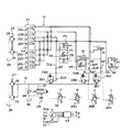
図2に示すように、上述した大型のローディングショベルに備えられる油圧駆動装置は、ブームシリンダ17、アームシリンダ16、バケットシリンダ19、および、開閉シリンダ20のそれぞれに供給される圧油の流れを制御するオープンセンタ型の方向切換弁群22を有する第1回路21と、方向切換弁群22を介さずにブームシリンダ17A,17B、アームシリンダ18、バケットシリンダ19、および、開閉シリンダ20のそれぞれに圧油を供給する第2回路26との2系統の回路を備えている。
As shown in FIG. 2, the hydraulic drive device provided in the large loading shovel described above controls the flow of pressure oil supplied to each of the
第1回路21は、原動機23により駆動される油圧ポンプ24,25を備えている。この第1回路21において、油圧ポンプ24は、バケット開閉用方向切換弁22a、第1ブーム用方向切換弁22b、第1アーム用方向切換弁22c、および、第1バケット用方向切換弁22dのそれぞれを介して、バケット開閉シリンダ20、第1ブームシリンダ17A、アームシリンダ18、バケットシリンダ19に接続してある。また、この第1回路21において、油圧ポンプ25は、第2バケット開閉用方向切換弁22e、第2ブーム用方向切換弁22f、第2アーム用方向切換弁22g、および、第2バケット用方向切換弁22hのそれぞれを介して、バケット開閉シリンダ20、第2ブームシリンダ17B、アームシリン18ダおよびバケットシリンダ19に接続してある。
The
第2回路26は、原動機27により駆動される油圧ポンプ28,29を備えている。この第2回路26は、油圧ポンプ28,29から吐出される圧油をブームシリンダ17A,17Bのそれぞれのボトム側に導く第1供給管路30Aを備えている。この第1供給管路30Aは、油圧ポンプ28,29に接続される吐出管路31と、この吐出管路31から分岐してブームシリンダ17A,17Bのそれぞれのボトム側に接続される第1分岐管路32Aとから構成してある。
The
第1分岐管路32Aには、ブームシリンダ17A,17Bのそれぞれのボトム側に流入する圧油の流量を制御する流入流量制御弁33Aを設けてある。この流入流量制御弁33Aは、制御弁34Aにより制御されるようにしてあり、この制御弁34Aは電磁比例減圧弁35Aにより制御されるようにしてある。
The
また、第2回路26は、油圧ポンプ28,29から吐出される圧油をバケットシリンダ19のボトム側に導く第2供給管路30Bを備えている。この第2供給管路30Bは、前記吐出管路31と、この吐出管路31から分岐してバケットシリンダ19のボトム側に接続される第2分岐管路32Bとから構成してある。
The
第2分岐管路32Bには、バケットシリンダ19のボトム側に流入する圧油の流量を制御する流入流量制御弁33Bを設けてある。この流入流量制御弁33Bは、制御弁34Bにより制御されるようにしてあり、この制御弁34Bは、電磁比例減圧弁35Bにより制御されるようにしてある。
The
また、第2回路26は、油圧ポンプ28,29から吐出される圧油をバケットシリンダ19のロッド側に導く第3供給管路30Cを備えている。この第3供給管路30Cは、前記吐出管路31と、この吐出管路31から分岐してバケットシリンダ19のロッド側に接続される第3分岐管路32Cとから構成してある。
The
第3分岐管路32Cには、バケットシリンダ19のロッド側に流入する圧油の流量を制御する流入流量制御弁33Cを設けてある。この流入流量制御弁33Cは、制御弁34Cにより制御されるようにしてあり、この制御弁34Cは、電磁比例減圧弁35Cにより制御されるようにしてある。
The third branch pipe 32C is provided with an inflow flow rate control valve 33C that controls the flow rate of the pressure oil that flows into the rod side of the
また、第2回路26は、第1〜第3供給管路30A〜30Cを構成する吐出管路31から分岐して作動油タンク36に接続されるバイパス管路37と、このバイパス管路37に設けられ、吐出管路37から作動油タンク36にバイパスされる圧油の流量を制御するバイパス流量制御弁38と、このバイパス流量制御弁38を制御する電磁比例減圧弁39とを備えている。つまり、第2回路26には、ブリードオフ回路を形成してある。
Further, the
また、図2において、40は、流入流量制御弁33Aよりもブームシリンダ17A,17B側において第1分岐管路32Aに設けられ、ブームシリンダ17A,17Bのボトム側から油圧ポンプ28,29側への圧油の逆流を阻止する逆止弁である。41は、流入流量制御弁33Bよりもバケットシリンダ19側において第2分岐管路32Bに設けられ、バケットシリンダ19のボトム側から油圧ポンプ28,29側への圧油の逆流を阻止する逆止弁である。42は、流入流量制御弁33Cよりもバケットシリンダ19側において第3分岐管路32Cに設けられ、バケットシリンダ19のロッド側から油圧ポンプ28,29側への圧油の逆流を阻止する逆止弁である。
In FIG. 2,
また、43は、ブームシリンダ17A,17Bのそれぞれのボトム側の圧油をロッド側に再生する(逃がす)再生流量制御弁である。44は、ブームシリンダ17A,17Bのそれぞれのボトム側からロッド側への圧油の逆流を阻止する逆止弁である。45は、アームシリンダ18のボトム側の圧油をロッド側に再生する再生流量制御弁である。46は、アームシリンダ18のボトム側からロッド側への圧油の逆流を阻止する逆止弁である。47は、バケット開閉シリンダ20のロッド側の圧油をボトム側に再生する再生流量制御弁である。48は、バケット開閉シリンダ20のロッド側からボトム側への圧油の流れを阻止する逆止弁である。また、49は、吐出管路31内の最大圧力を規定するリリーフ弁である。
また、50は、操作レバー50aの操作量に対応する操作信号(電気信号)を出力することによって、ブーム上げ・ブームの下げおよびブーム14の動作速度を指示する指示装置である。51は、操作レバー51aの操作量に対応する操作信号(電気信号)を出力することによって、アームクラウド・アームダンプおよびアーム15の動作速度を指示する指示装置である。52は、操作レバー52aの操作量に対応する操作信号(電気信号)を出力することによって、バケットクラウド・バケットダンプおよびバケット16の動作速度を指示する指示装置である。
また、53は、指示装置50〜52のそれぞれからの操作信号に応じて、電磁比例減圧弁35A〜35C,39、再生流量制御弁43,45,47を制御する制御装置である。
なお、図2において、前記走行モータ、この走行モータを駆動させる回路、走行を指示する指示装置、旋回モータ、この旋回モータを駆動させる回路、旋回を指示する指示装置は省略してある。また、バケット開閉を指示する指示装置も、省略してある。 In FIG. 2, the traveling motor, a circuit for driving the traveling motor, an instruction device for instructing traveling, a turning motor, a circuit for driving the turning motor, and an instruction device for instructing turning are omitted. An instruction device for instructing opening and closing of the bucket is also omitted.
<2> 第1の実施形態
<2−1> 第1実施形態の構成
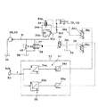
第1の実施形態の構成について図3,4を用いて説明する。図3は、第1の実施形態の構成を示す油圧回路図、図4は、図3に示す流入流量制御弁の構造を示す断面図である。
<2> First Embodiment <2-1> Configuration of First Embodiment The configuration of the first embodiment will be described with reference to FIGS. FIG. 3 is a hydraulic circuit diagram showing the configuration of the first embodiment, and FIG. 4 is a cross-sectional view showing the structure of the inflow flow rate control valve shown in FIG.
第1の実施形態は、「<1>」で述べた大型のローディングショベルの第2回路26に3つ設けてある。
In the first embodiment, three are provided in the
1つ目は、油圧ポンプ28,29、第1供給管路30A、流入流量制御弁33A、制御弁34A、電磁比例減圧弁35A、バイパス管路37、バイパス流量制御弁38、電磁比例減圧弁39、指示装置50、および制御装置53を備える構成部分である。
The first is the
2つ目は、油圧ポンプ28,29、第2供給管路30B、流入流量制御弁33B、制御弁34B、電磁比例減圧弁35B、バイパス管路37、バイパス流量制御弁38、電磁比例減圧弁39、指示装置51、および制御装置53を備える構成部分である。
The second is the
3つ目は、油圧ポンプ28,29、第3供給管路30C、流入流量制御弁33C、制御弁34C、電磁比例減圧弁35C、バイパス管路37、バイパス流量制御弁38、電磁比例減圧弁39、指示装置52、および制御装置53とを備える構成部分である。
The third is the
これらの3つの構成部分は同様の構成なので、1つ目に述べた構成部分を例に挙げて第1の実施形態を説明する。 Since these three components have the same configuration, the first embodiment will be described by taking the first component as an example.
第1の実施形態は、図3に示す油圧駆動装置であり、上述したように油圧ポンプ28,29、第1供給管路30A、流入流量制御弁33A、制御弁34A、電磁比例減圧弁35A、バイパス管路37、バイパス流量制御弁38、電磁比例減圧弁39、指示装置50、および制御装置53を備える構成にしてある。
The first embodiment is the hydraulic drive device shown in FIG. 3, and as described above, the
第1の実施形態では、流入流量制御弁33Aおよびバイパス流量制御弁38の作動を指示する指示手段が、指示装置50であり、制御装置53と、電磁比例減圧弁35Aと、制御弁34Aとから、指示装置50による指示、すなわち操作信号(電気信号)に応じて流入流量制御弁33Aを制御する流入用制御手段を構成してある。この流入用制御手段のうち、電磁比例減圧弁35Aと制御弁34Aは、バイパス流量制御弁33Aを駆動させる流入用駆動手段である。また、制御装置53と、電磁比例減圧弁39とから、指示装置50による指示、すなわち操作信号(電気信号)に応じてバイパス流量制御弁38を制御するバイパス用制御手段を構成してある。このバイパス用制御手段のうち、電磁比例減圧弁39は、バイパス流量制御弁38を駆動させるバイパス用駆動手段である。
In the first embodiment, the instruction means for instructing the operation of the inflow flow
流入流量制御弁33Aは、図3,4に示すように、中立時に閉じており、作動時に開く中立クローズ型のシート弁からなる。この流入流量制御弁33Aは、ケーシング33a内に設けられる弁室33bと、この弁室33bに摺動可能に設けられる弁体33cと、吐出管路31と弁室33bとを接続する入口管路33dと、第1分岐管路32Aのブームシリンダ17A,17B側と弁室33bとを接続する出口管路33eとを備えている。
As shown in FIGS. 3 and 4, the inflow flow rate control valve 33 </ b> A is a neutral closed-type seat valve that is closed during neutral operation and opened during operation. The inflow flow
弁体33cは、軸方向の両端に設けられる第1受圧面33fおよび第2受圧面33gと、弁体33cの中間部に設けられる第3受圧面33hとを有する。弁室33bには、第1受圧面33fが配置されこの第1受圧面33fに圧力を作用させる圧油が導入される背圧室33iと、第3受圧面33hに入口管路33dの圧力を作用させる油室33jと、出口管路33eと弁室33bとを連通させる開口部の縁に設けられ、弁体33cの第2受圧面33gの縁が接触・離反する弁座33kとを備えている。
The
弁体33cの周側面には、入口管路33dの圧油を背圧室33iに導くスリット33lと、このスリット33lを背圧室33iに対して開閉する突出部33mとを形成してある。また、背圧室33iには、弁体33cを出口管路33g側に復帰させる復帰ばね33nを設けてある。
On the peripheral side surface of the
制御弁34Aは、中立時に閉じており、作動時に開く中立クローズ型のスプール弁である。この制御弁34Aは、流入流量制御弁33Aの背圧室33iと出口管路33eとを接続する管路34bに設けてある。
The
図3に示すように、電磁比例減圧弁35Aは、制御装置53からの目標指令信号(電気信号)を可変式電磁アクチュエータ35aに与えられて動作し、図示しないパイロットポンプから吐出された圧力を、目標指令信号の目標指令値(電流値)に応じたパイロット圧力に変換して出力するものである。この電磁比例減圧弁35Aから出力されたパイロット圧力は、パイロット管路35bを介して制御弁34Aのパイロット受圧室34aに与えられるようにしてある。
As shown in FIG. 3, the electromagnetic proportional
バイパス流量制御弁38は、中立時に開き作動時に閉じる中立オープン型のスプール弁である。
The bypass flow
電磁比例減圧弁39は、制御装置53からの目標指令信号(電気信号)を可変式電磁アクチュエータ39aに与えられて動作し、図示しないパイロットポンプから吐出された圧力を、目標指令信号の目標指令値(電流値)に応じたパイロット圧力に変換して出力するものである。この電磁比例減圧弁39から出力されたパイロット圧力は、パイロット管路39bを介して制御弁34Aのパイロット受圧室34aに与えられるようにしてある。
The electromagnetic proportional
制御装置53は、電磁比例減圧弁35Aを制御するための目標指令信号を出力する流入用制御部54と、電磁比例減圧弁39を制御するための目標指令信号を出力するバイパスバイパス用制御部55と、バイパス流量制御弁38の立上り応答が、流入流量制御弁33Aの立上り応答よりも遅くなり、流入流量制御弁33Aの立下り応答が、バイパス流量制御弁38の立下り応答よりも遅くなるように、流入流量制御弁33Aおよびバイパス流量制御弁38の応答を補正する応答補正手段とを備えている。
The
流入用制御部54は、指示装置50からの操作信号(操作量X)に対応する流入流量制御弁33Aの弁体33cのストローク目標指令値Saを算出する流入用ストローク目標指令値演算器54と、この流入用ストローク目標指令値演算器54により算出されたストローク目標指令値Saに対し遅れ処理を施してストローク目標指令値Sbを算出する流入用遅れ処理器54bと、ストローク目標指令値Sa,Sbのうちの大きい方を選択する最大値選択器54dと、この最大値選択器54dにより選択されたストローク目標指令値に応じて電磁比例減圧弁35Aに与える目標指令値(電流値)を算出する流入用目標指令値演算器54dとを備えている。
The
バイパス用制御部55は、指示装置50からの操作信号(操作量X)に対応するバイパス流量制御弁38のストローク目標指令値Scを算出するバイパス用ストローク目標指令値演算器55aと、このバイパス用ストローク目標指令値演算器55aにより算出されたストローク目標指令値Scに対し遅れ処理を施してストローク目標指令値Sdを算出するバイパス用遅れ処理器55bと、ストローク目標指令値Sc,Sdのうちの小さい方を選択する最小値選択器55cと、この最小値選択器55cにより選択されたストローク目標指令値に応じて電磁比例減圧弁39に与える目標指令値を算出する目標指令値演算器55dとを備えている。
The
応答補正手段は、流入用制御部54の遅れ処理器54bおよび最大値選択器54cと、バイパス用制御部55の遅れ処理器55bおよび最小値選択器55cとから構成してある。
The response correction means includes a
応答補正手段において、流入用制御部54の遅れ処理器54bは、時定数T1の1次遅れに基づく遅れ処理が行われるように設定してある。また、バイパス用制御部55の遅れ処理器55bは、時定数T2の1次遅れに基づく遅れ処理が行われるように設定してある。時定数T1は、バイパス流量制御弁38が開く際の時定数よりも大きく設定してあり、時定数T2は、流入流量制御弁33Aが開く際の時定数よりも大きく設定してある。
In the response correction means, the
<2−2> 第1の実施形態の動作
[A]操作レバー50aがステップ状に傾倒されたときの動作
流入流量制御弁33Aは閉位置にあり、バイパス流量制御弁38は開位置にあるとする。この状態で、オペレータがブーム上げを指示するために、例えば操作レバー50aを急速に、すなわちステップ状に、傾倒させると、指示装置50から制御装置53に操作信号がステップ入力される。
<2-2> Operation of the First Embodiment [A] Operation when the
[A−1] 流入流量制御弁33Aの制御
制御装置53に操作信号がステップ入力されると、次のようにして流入流量制御弁33Aの制御が行われる。
[A-1] Control of Inflow
制御装置53の流入用制御部54において、はじめに、流入用ストローク目標指令値演算器54aによって、流入流量制御弁33Aのストローク目標指令値Saが算出される。次に、流入用遅れ処理器54bによって、ストローク目標指令値Saに遅れ処理が施されてストローク目標指令値Sbが算出される。次に、最大値選択器54cによって、ストローク目標指令値Sa,Sbのうちの大きい方が選択される。
In the
今は、ブーム上げが指示されている。すなわち、流入流量制御弁33Aを開いて、言い換えると、流入流量制御弁33Aの弁体33cのストロークを増加させて、ブームシリンダ17A,17Bのボトム側に圧油を供給する旨が指示されている。このため、流入用ストローク目標指令値演算器54aにより算出されたストローク目標指令値Saが、流入用遅れ処理器54bにより算出されたストローク目標指令値Sbよりも大きい。したがって、最大値選択器54cによってストローク目標指令値Saが選択される。
Now it is instructed to raise the boom. That is, it is instructed to open the inflow flow
次に、流入用目標指令値演算器55bによって、ストローク目標指令値Saに対応する電磁比例減圧弁35Aの目標指令値が算出される。そして、制御装置53から目標指令値に対応する目標指令信号が出力され、電磁比例減圧弁35Aの可動式電磁アクチュエータ35aに与えられる。
Next, the target command value for the electromagnetic proportional
すると、電磁比例減圧弁35Aの可動式電磁アクチュエータ35aが、パイロット圧力を増加させる方向に駆動し、電磁比例減圧弁35Aから制御弁34Aのパイロット受圧室34aに、パイロット管路35bを介してパイロット圧力が与えられる。これにより、制御弁34Aが開き、これに伴って、流入流量制御弁33Aが開く方向に動作する。この結果、油圧ポンプ28,29から吐出された圧油が第1供給管路30Aおよび流入流量制御弁33Aを介してブームシリンダ17A,17Bのボトム側に導かれ、ブームシリンダ17A,17Bが伸長してブーム上げが行われる。
Then, the movable
[A−2] バイパス流量制御弁38の制御
「[A−1]」で述べたようにして流入流量制御弁33Aが制御されている間、次のようにしてバイパス流量制御弁38の制御が行われる。
[A-2] Control of Bypass
制御装置53のバイパス用制御部55において、はじめに、バイパス用ストローク目標指令値演算器55aによって、バイパス流量制御弁38のストローク目標指令値Scが算出される。次に、バイパス用遅れ処理器55bによって、ストローク目標指令値Scに遅れ処理が施されてストローク目標指令値Sdが算出される。次に、最小値選択器55cによって、ストローク目標指令値Sc,Sdのうちの小さい方が選択される。
In the
今は、ブーム上げが指示されている。すなわち、バイパス流量制御弁38を閉じる方向に動作させて、言い換えると、バイパス流量制御弁38のスプールのストロークを増加させて、第1供給管路30Aからバイパスされる圧油の流量を減少させる旨が指示されている。このため、バイパス用遅れ処理器55bにより算出されたストローク目標指令値Sdが、ストローク目標指令値演算器55aにより算出されたストローク目標指令値Scがよりも小さい。したがって、最小値選択器55cによってストローク目標指令値Sdが選択される。
Now it is instructed to raise the boom. That is, the bypass flow
次に、バイパス用目標指令値演算器55dによって、ストローク目標指令値Sdに対応する目標指令値が算出される。そして、制御装置53から目標指令値に対応する目標指令信号が出力され、電磁比例減圧弁39の可動式電磁アクチュエータ39aに与えられる。
Next, a target command value corresponding to the stroke target command value Sd is calculated by the bypass target
すると、電磁比例減圧弁39の可動式電磁アクチュエータ39aが、パイロット圧力を増加させる方向に駆動し、電磁比例減圧弁39からバイパス流量制御弁38に、パイロット管路39bを介してパイロット圧力が与えられる。これにより、バイパス流量制御弁38が閉じる方向に動作し、この結果、第1供給管路30Aからバイパスされる圧油の流量が減少する。
Then, the movable
[B] 操作レバー50aがステップ状に中立に戻されたときの動作
流入流量制御弁33Aは開位置にあり、バイパス流量制御弁38は閉位置にあるとする。この状態で、オペレータがブーム上げの停止を指示するために、例えば操作レバー50aをステップ状に戻すと、指示装置50から制御装置53への操作信号の入力がステップ状に停止する。
[B] Operation when the
[B−1] 流入流量制御弁33Aの制御
制御装置53への操作信号がステップ状に停止されると、次のようにして流入流量制御弁33Aの制御が行われる。
[B-1] Control of Inflow Flow
制御装置53の流入用制御部54において、はじめに、流入用ストローク目標指令値演算器54aによって、流入流量制御弁33Aのストローク目標指令値Saが算出される。次に、流入用遅れ処理器54bによって、ストローク目標指令値Saに遅れ処理が施されてストローク目標指令値Sbが算出される。次に、最大値選択器54cによって、ストローク目標指令値Sa,Sbのうちの大きい方が選択される。
In the
今は、ブーム上げの停止が指示されている。すなわち、流入流量制御弁33Aを閉じて、言い換えると流入流量制御弁33Aの弁体33cのストロークを0まで減少させて、ブームシリンダ17A,17Bのボトム側からの圧油の流出を阻止する旨が指示されている。このため、流入用遅れ処理器54bにより算出されたストローク目標指令値Sbが、流入用ストローク目標指令値演算器54aにより算出されたストローク目標指令値Saよりも大きい。したがって、最大値選択器55cによってストローク目標指令値Sbが選択される。
Now, it is instructed to stop raising the boom. That is, the inflow flow
次に、流入用目標指令値演算器54dによって、ストローク目標指令値Sbに対応する目標指令値が算出される。そして、制御装置53から目標指令値に対応する目標指令信号が出力され、電磁比例減圧弁35Aの可動式電磁アクチュエータ35aに与えられる。
Next, a target command value corresponding to the stroke target command value Sb is calculated by the inflow target
すると、電磁比例減圧弁35Aの可動式電磁アクチュエータ35aが、パイロット圧力を減少させる方向に駆動し、制御弁34Aのパイロット受圧室34aの圧油がパイロット管路35bおよび電磁比例減圧弁35Aを介して作動油タンク36に排出される。これにより、制御弁34Aが閉じ、これに伴って、流入流量制御弁33Aが閉じる。この結果、油圧ポンプ28,29とブームシリンダ17A,17Bのボトム側との間が遮断されて、ブームシリンダ17A,17Bの伸長が停止してブーム上げが停止する。
Then, the movable
[B−2] バイパス流量制御弁38の制御
「[B−1]」で述べたようにして流入流量制御弁33Aが制御されている間、次のようにしてバイパス流量制御弁38の制御が行われる。
[B-2] Control of Bypass
制御装置53のバイパス用制御部55において、はじめに、バイパス用ストローク目標指令値演算器55aによって、バイパス流量制御弁38のストローク目標指令値Scが算出される。次に、バイパス用遅れ処理器55bによって、ストローク目標指令値Scに遅れ処理が施されてストローク目標指令値Sdが算出される。次に、最小値選択器によって、ストローク目標指令値Sc,Sdのうちの小さい方が選択される。
In the
今は、ブーム上げの停止が指示されている。すなわち、バイパス流量制御弁38が開く方向にスプールをストロークさせて、言い換えると、スプールのストロークを0まで減少させて第1供給管路30Aからバイパスされる圧油の流量を増加させる旨が指示されている。このため、バイパス用ストローク目標指令値演算器55aにより算出されたストローク目標指令値Scが、バイパス用遅れ処理器55bにより算出されたストローク目標指令値Sdよりも小さい。したがって、最小値選択器55cによってストローク目標指令値Scが選択される。
Now, it is instructed to stop raising the boom. That is, it is instructed to stroke the spool in the direction in which the bypass flow
次に、バイパス用目標指令値演算器55dによって、ストローク目標指令値Scに対応する目標指令値が算出される。そして、制御装置53から目標指令値に対応する目標指令信号が出力され、電磁比例減圧弁39の可動式電磁アクチュエータ39aに与えられる。
Next, a target command value corresponding to the stroke target command value Sc is calculated by the bypass target
すると、電磁比例減圧弁39の可動式電磁アクチュエータ39aが、パイロット圧力を減少させる方向に駆動し、バイパス流量制御弁38のパイロット受圧室38aの圧力が、パイロット管路39bおよび電磁比例減圧弁39を介して作動油タンク36に排出される。これにより、バイパス流量制御弁38が開く方向に動作し、この結果、第1供給管路30Aからバイパスされる圧油の流量が増加する。
Then, the movable
[C] 流入流量制御弁33Aとバイパス流量制御弁38との動作の協調
[C−1] 操作レバー50aがステップ状に傾倒されたとき
操作レバー50aがステップ状に傾倒されたとき、流入流量制御弁33Aに対しては、「[A−1]」で述べたように、ストローク目標指令値Saに遅れ処理を施さない制御が行われる。一方、バイパス流量制御弁38に対しては、「[A−2]」で述べたように、ストローク目標指令値Scに遅れ処理を施した制御が行われる。これにより、図11(b),(c)に破線で示すように、バイパス流量制御弁38のストロークの立上り応答が、流入流量制御弁33Aのストロークの立上り応答よりも遅れる。
[C] Coordination of operation of the inflow flow
この結果、バイパス流量制御弁38が閉じ流入流量制御弁33Aが開く際、流入流量制御弁33Aのストロークの開始から完了までの間、同図11(d),(e)に破線で示すように、流入流量制御弁33Aの開口面積の増加分が、バイパス流量制御弁38の開口面積の減少分を上回った状態が維持される。これにより、流入流量制御弁33Aの開口面積とバイパス流量制御弁38の開口面積との合計は、油圧ポンプ28,29から吐出された圧力がブームシリンダ17A,17Bや作動油タンク36に円滑に逃げる大きさに維持される。したがって、第1供給管路30A内におけるサージ圧の発生が防止される。
As a result, when the bypass flow
[C−2] 操作レバー50aがステップ状に戻されたとき
操作レバー50aがステップ状に戻されたとき、流入流量制御弁33Aに対しては、「[B−1]」で述べたように、ストローク目標指令値Saに遅れ処理を施して流入流量制御弁33Aの制御が行われる。一方、バイパス流量制御弁38に対しては、「[B−2]」で述べたように、ストローク目標指令値Scに遅れ処理を施さない制御が行われる。これにより、同図11(b),(c)に破線で示すように、流入流量制御弁33Aのストロークの立下り応答が、バイパス流量制御弁38のストロークの立下り応答よりも遅れる。
[C-2] When the
この結果、バイパス流量制御弁38が開き流入流量制御弁33Aが閉じる際、バイパス流量制御弁38のが開く方向へのストロークの開始から完了までの間、同図11(d),(e)に示すように、バイパス流量制御弁38の開口面積の増加分が、流入流量制御弁33Aの開口面積の減少分を上回った状態が維持される。これにより、流入流量制御弁33Aの開口面積とバイパス流量制御弁38の開口面積との合計は、油圧ポンプ28,29から吐出された圧力がブームシリンダ17A,17Bや作動油タンク36に円滑に逃げる大きさに維持される。したがって、第1供給管路30A内におけるサージ圧の発生が防止される。
As a result, when the bypass
<2−3> 第1の実施形態の効果
第1の実施形態によれば次の効果を得られる。
<2-3> Effects of First Embodiment According to the first embodiment, the following effects can be obtained.
第1の実施形態では、制御装置53に、流入用遅れ処理器54bおよび最大値選択器54cと、バイパス用遅れ処理器55bおよび最小値選択器55cとから構成した応答補正手段を設けたことによって、第1〜第3供給管路30A〜30C内におけるサージ圧の発生を防止できる。したがって、ブームシリンダ17A,17Bおよびバケットシリンダ19の操作性の悪化、ポンプ吐出圧の安定性の悪化、騒音の発生、機器の寿命の低下などの防止に貢献できる。
In the first embodiment, the
また、第1の実施形態では、流入流量制御弁33A〜33Cのストローク目標指令値Saおよびバイパス流量制御弁38のストローク目標指令値Scのそれぞれに遅れ処理が施される。これにより、操作レバー50aを緩やかに操作した場合における流入流量制御弁33A〜33Cおよびバイパス流量制御弁38のそれぞれの静的な応答特性を維持でき、操作レバー50aをスッテップ状に操作した場合における流入流量制御弁33A〜33Cおよびバイパス流量制御弁38のそれぞれの動的な応答特性を補正することができる。この結果、流入流量制御弁33A〜33Cおよびバイパス流量制御弁38を、静的な応答特性のみを考慮して設計することができ、したがって、流入流量制御弁33A〜33Cおよびバイパス流量制御弁38のそれぞれの設計を容易にすることができる。
In the first embodiment, delay processing is performed on each of the stroke target command value Sa of the inflow flow
また、第1の実施形態では、遅れ処理が1次遅れによる。つまり、流入流量制御弁33A〜33Cおよびバイパス流量制御弁38のそれぞれの応答の補正が、簡単な関数に基づいて行われる。これにより、流入流量制御弁33A〜33Cおよびバイパス流量制御弁38のそれぞれの応答がどのように補正されるかが分かりやすく、したがって、流量制御弁33A〜33Cおよびバイパス流量制御弁38のそれぞれの応答を簡単に補正することができる。
In the first embodiment, the delay process is based on the first-order delay. That is, the correction of the responses of the inflow flow
また、第1の実施形態では、流入流量制御弁33A〜33Cを小型でも大流量を扱うことが可能なシート弁とした。これにより、油圧回路の小型化に貢献できる。
Further, in the first embodiment, the inflow flow
<3> 第2の実施形態
<3−1> 第2の実施形態の構成
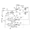
第2の実施形態の構成について図5を用いて説明する。図5は、第2の実施形態の構成を示す油圧回路図である。図5において、図3に示す同等のものには、図3に付した符号と同じ符号を付してある。
<3> Second Embodiment <3-1> Configuration of Second Embodiment The configuration of the second embodiment will be described with reference to FIG. FIG. 5 is a hydraulic circuit diagram showing the configuration of the second embodiment. 5, the same components as those shown in FIG. 3 are denoted by the same reference numerals as those shown in FIG.
第2の実施形態は、バイパス流量制御弁38の応答を流入流量制御弁33Aの応答よりも遅く構成した点、制御装置53の流入用遅れ処理器54bおよび最大値選択器54cのみから応答補正手段を構成してある点で、第1の実施形態と異なっており、これ以外の第2の実施形態の構成は、第1の実施形態と同様である。
In the second embodiment, the response correction means is constituted only by the point that the response of the bypass flow
第2の実施形態を上述のように構成した理由は、次のことに基づいている。 The reason why the second embodiment is configured as described above is based on the following.
「<2>」で述べたように第1の実施形態は、大型のローディングショベル10に備えられるものであり、したがって、バイパス流量制御弁38に備えられるスプールは、大型のローディングショベル10に対応した大流量の圧油を扱うことができる大型のものである。このため、バイパス流量制御弁38のスプールの駆動に必要なパイロット圧油の流量に対して、電磁比例減圧弁39からバイパス流量制御弁38のパイロット受圧室38aに供給するパイロット圧油の流量が不足気味になる。言い換えると、パイロット受圧室38aに供給するパイロット圧油の流量が不足気味になるように電磁比例減圧弁39の構成をすることで、容易にバイパス流量制御弁38の応答をシート弁からなる流入流量制御弁33Aの応答よりも遅くすることができる。
As described in “<2>”, the first embodiment is provided in the large-
<3−2> 第2の実施形態の動作
[A]操作レバー50aがステップ状に傾倒されたときの動作
流入流量制御弁33Aは閉位置にあり、バイパス流量制御弁38は開位置にあるとする。この状態で、オペレータがブーム上げを指示するために、例えば操作レバー50aを急速に、すなわちステップ状に、傾倒させると、指示装置50から制御装置53に操作信号がステップ入力される。
<3-2> Operation of the Second Embodiment [A] Operation when the
[A−1] 流入流量制御弁33Aの制御
制御装置53に操作信号がステップ入力されると、次のようにして流入流量制御弁33Aの制御が行われる。
[A-1] Control of Inflow
制御装置53の流入用制御部54において、はじめに、流入用ストローク目標指令値演算器54aによって、流入流量制御弁のストローク目標指令値Saが算出される。次に、流入用遅れ処理器54bによって、ストローク目標指令値Saに遅れ処理が施されてストローク目標指令値Sbが算出される。次に、最大値選択器によって、ストローク目標指令値Sa,Sbのうちの大きい方が選択される。
In the
今は、ブーム上げが指示されている。すなわち、流入流量制御弁33Aを開いて、言い換えると、流入流量制御弁33Aの弁体のストロークを増加させて、ブームシリンダ17A,17Bのボトム側に圧油を供給する旨が指示されている。このため、流入用ストローク目標指令値演算器54aにより算出されたストローク目標指令値Saが、流入用遅れ処理器54bにより算出されたストローク目標指令値Sbよりも大きい。したがって、最大値選択器54cによってストローク目標指令値Saが選択される。
Now it is instructed to raise the boom. That is, it is instructed to open the inflow flow
次に、流入用目標指令値演算器54dによって、ストローク目標指令値Saに対応する目標指令値が算出される。そして、制御装置53から目標指令値に対応する目標指令信号が出力され、電磁比例減圧弁35Aの可動式電磁アクチュエータ35aに与えられる。
Next, the target command value corresponding to the stroke target command value Sa is calculated by the inflow target
すると、電磁比例減圧弁35Aの可動式電磁アクチュエータ35aが、パイロット圧力を増加させる方向に駆動し、電磁比例減圧弁35Aから制御弁34Aのパイロット受圧室34aに、パイロット管路35bを介してパイロット圧力が与えられる。これにより、制御弁34Aが開き、これに伴って、流入流量制御弁33Aが開く方向に動作する。この結果、油圧ポンプ28,29から吐出された圧油が第1供給管路30Aおよび流入流量制御弁33Aを介してブームシリンダ17A,17Bのボトム側に導かれ、ブームシリンダ17A,17Bが伸長してブーム上げが行われる。
Then, the movable
[A−2] バイパス流量制御弁38の制御
「[A−1]」で述べたようにして流入流量制御弁33Aが制御されている間、次のようにしてバイパス流量制御弁38の制御が行われる。
[A-2] Control of Bypass
制御装置53のバイパス用制御部56において、はじめに、バイパス用ストローク目標指令値演算器55aによって、バイパス流量制御弁38のストローク目標指令値Scが算出される。次に、バイパス用目標指令値演算器55dによって、ストローク目標指令値Scに対応する目標指令値が算出される。そして、制御装置53から目標指令値に対応する目標指令信号が出力され、電磁比例減圧弁39の可動式電磁アクチュエータ39aに与えられる。
In the
すると、電磁比例減圧弁39の可動式電磁アクチュエータ39aが、パイロット圧力を増加させる方向に駆動し、電磁比例減圧弁39からバイパス流量制御弁38にパイロット管路39bを介してパイロット圧力が与えられる。これにより、バイパス流量制御弁38が閉じる方向に動作し、この結果、第1供給管路30Aからバイパスされる圧油の流量が減少する。
Then, the movable
[B] 操作レバー50aがステップ状に中立に戻されたときの動作
流入流量制御弁33Aは開位置にあり、バイパス流量制御弁38は閉位置にあるとする。この状態で、オペレータがブーム上げの停止を指示するために、例えば操作レバー50aをステップ状に戻すと、指示装置50から制御装置53への操作信号の入力がステップ状に停止する。
[B] Operation when the
[B−1] 流入流量制御弁33Aの制御
制御装置53への操作信号がステップ状に停止されると、次のようにして流入流量制御弁33Aの制御が行われる。
[B-1] Control of Inflow Flow
制御装置53の流入用制御部54において、はじめに、流入用ストローク目標指令値演算器54aによって、流入流量制御弁33Aのストローク目標指令値Saが算出される。次に、流入用遅れ処理器54bによって、ストローク目標指令値Saに遅れ処理が施されてストローク目標指令値Sbが算出される。次に、最大値選択器54cによって、ストローク目標指令値Sa,Sbのうちの大きい方が選択される。
In the
今は、ブーム上げの停止が指示されている。すなわち、流入流量制御弁33Aを閉じて、言い換えると、流入流量制御弁33Aの弁体33cのストロークを0まで減少させて、ブームシリンダ17A,17Bのボトム側からの圧油の流出を阻止する旨が指示されている。このため、流入用遅れ処理器54bにより算出されたストローク目標指令値Sbが、流入用ストローク目標指令値演算器54aにより算出されたストローク目標指令値Saよりも大きい。したがって、最大値選択器54cによってストローク目標指令値Sbが選択される。
Now, it is instructed to stop raising the boom. That is, the inflow flow
次に、流入用目標指令値演算器54dによって、ストローク目標指令値Sbに対応する目標指令値が算出される。そして、制御装置53から目標指令値に対応する目標指令信号が出力され、電磁比例減圧弁35Aの可動式電磁アクチュエータ35aに与えられる。
Next, a target command value corresponding to the stroke target command value Sb is calculated by the inflow target
すると、電磁比例減圧弁35Aの可動式電磁アクチュエータ35aが、パイロット圧力を減少させる方向に駆動し、制御弁34のパイロット受圧室34aの圧油がパイロット管路35bおよび電磁比例減圧弁35を介して作動油タンク36に排出される。これにより、制御弁34Aが閉じ、これに伴って、流入流量制御弁33Aが閉じる。この結果、油圧ポンプ28,29とブームシリンダ17A,17Bのボトム側との間が遮断されて、ブームシリンダ17A,17Bの伸長が停止してブーム上げが停止する。
Then, the movable
[B−2] バイパス流量制御弁38の制御
「[B−1]」で述べたようにして流入流量制御弁33Aが制御されている間、次のようにしてバイパス流量制御弁38の制御が行われる。
[B-2] Control of Bypass
制御装置53のバイパス用制御部56において、はじめに、バイパス用ストローク目標指令値演算器55aによって、バイパス流量制御弁38のストローク目標指令値Scが算出される。次に、バイパス用目標指令値演算器55dによって、ストローク目標指令値Scに対応する目標指令値が算出される。そして、制御装置53から目標指令値に対応する目標指令信号が出力され、電磁比例減圧弁39の可動式電磁アクチュエータ39aに与えられる。
In the
すると、電磁比例減圧弁39の可動式電磁アクチュエータ39aが、パイロット圧力を減少させる方向に駆動し、バイパス流量制御弁38のパイロット受圧室38aの圧油が、パイロット管路39bおよび電磁比例減圧弁39を介して作動油タンク36に排出される。これにより、バイパス流量制御弁38が開く方向に動作し、この結果、第1供給管路30Aからバイパスされる圧油の流量が増加する。
Then, the movable
[C] 流入流量制御弁33Aとバイパス流量制御弁38との動作の協調
[C−1] 操作レバー50aがステップ状に傾倒されたとき
操作レバー50aがステップ状に傾倒されたとき、流入流量制御弁33Aに対しては、「[A−1]」で述べたように、ストローク目標指令値Saに遅れ処理を施されない制御が行われる。一方、バイパス流量制御弁38に対しては、ストローク目標指令値Scに従ったバイパス流量制御弁38の制御が行われる。つまり、バイパス流量制御弁38の応答を流入流量制御弁33Aの応答よりも遅く構成してあるので、この構成を利用して流入流量制御弁33Aとバイパス流量制御弁38の制御が行われる。これにより、図11(b),(c)に破線で示すように、バイパス流量制御弁38のストロークの立上り応答が、流入流量制御弁33Aのストロークの立上り応答よりも遅れる。
[C] Coordination of operation of the inflow flow
この結果、バイパス流量制御弁38が閉じ流入流量制御弁33Aが開く際、流入流量制御弁33Aのストロークの開始から完了までの間、同図11(d),(e)に破線で示すように、流入流量制御弁33Aの開口面積の増加分が、バイパス流量制御弁38の開口面積の減少分を上回った状態が維持される。これにより、流入流量制御弁33Aの開口面積とバイパス流量制御弁38の開口面積との合計は、油圧ポンプ28,29から吐出された圧力がブームシリンダ17A,17Bや作動油タンク36に円滑に逃げる大きさに維持される。したがって、第1供給管路30A内におけるサージ圧の発生が防止される。
As a result, when the bypass flow
[C−2] 操作レバー50aがステップ状に戻されたとき
操作レバー50aがステップ状に戻されたとき、流入流量制御弁33Aに対しては、「[B−1]」で述べたように、ストローク目標指令値Saに遅れ処理を施した制御が行われる。一方、バイパス流量制御弁38に対しては、「[B−2]」で述べたように、ストローク目標指令値Scに従ったバイパス流量制御弁38の制御が行われる。これにより、同図11(b),(c)に破線で示すように、流入流量制御弁33Aのストロークの立下り応答が、バイパス流量制御弁38のストロークの立下り応答よりも遅れる。
[C-2] When the
この結果、バイパス流量制御弁38が開き流入流量制御弁33Aが閉じる際、バイパス流量制御弁38のが開く方向へのストロークの開始から完了までの間、同図11(d),(e)に示すように、バイパス流量制御弁38の開口面積の増加分が、流入流量制御弁33Aの開口面積の減少分を上回った状態が維持される。これにより、流入流量制御弁33Aの開口面積とバイパス流量制御弁38の開口面積との合計は、油圧ポンプ28,29から吐出された圧力がブームシリンダ17A,17Bや作動油タンク36に円滑に逃げる大きさに維持される。したがって、第1供給管路30A内におけるサージ圧の発生が防止される。
As a result, when the bypass
<3−3> 第2の実施形態の効果
第2の実施形態によれば次の効果を得られる。
<3-3> Effects of Second Embodiment According to the second embodiment, the following effects can be obtained.
第2の実施形態では、流入流量制御弁33A〜33Cの応答をバイパス流量制御弁38の応答よりも早く構成し、制御装置53に、流入用遅れ処理器54bおよび最大値選択器54cから構成した応答補正手段を設けたことによって、第1〜第3供給管路30A〜30C内におけるサージ圧の発生を防止できる。したがって、ブームシリンダ17A,17Bおよびバケットシリンダ19の操作性の悪化、ポンプ吐出圧の安定性の悪化、騒音の発生、機器の寿命の低下などの防止に貢献できる。
In the second embodiment, the responses of the inflow flow
また、第2の実施形態では、第1の実施形態には備えされていたバイパス用遅れ処理器55bおよび最小値選択器55cを省いてある。これにより、制御装置53の構成を簡単にすることができる。
In the second embodiment, the
また、第2の実施形態では、流入流量制御弁33A〜33Cのストローク目標指令値Saに遅れ処理が施される。これにより、操作レバー50aを緩やかに操作した場合における流入流量制御弁33A〜33Cのそれぞれの静的な応答特性を維持でき、操作レバー50aをスッテップ状に操作した場合における流入流量制御弁33A〜33Cのそれぞれの動的な応答特性を補正することができる。この結果、流入流量制御弁33A〜33Cを、静的な応答特性のみを考慮して設計することができ、したがって、流入流量制御弁33A〜33Cのそれぞれの設計を容易にすることができる。
In the second embodiment, a delay process is performed on the stroke target command value Sa of the inflow flow
また、第2の実施形態では、遅れ処理が1次遅れによる。つまり、流入流量制御弁33A〜33Cのそれぞれの応答の補正が、簡単な関数に基づいて行われる。これにより、流入流量制御弁33A〜33Cのそれぞれの応答がどのように補正されるかが分かりやすく、したがって、流量制御弁33A〜33Cのそれぞれの応答を簡単に補正することができる。
In the second embodiment, the delay process is based on the first-order delay. That is, the correction of each response of the inflow flow
<4> 第3の実施形態
<4−1> 第3の実施形態の構成
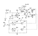
第3実施形態の構成について図6を用いて説明する。図6は、第3の実施形態の構成を示す油圧回路図である。図6において、図3,5に示すものと同等ものには、図3,5に付した符号と同じ符号を付してある。
<4> Third Embodiment <4-1> Configuration of Third Embodiment The configuration of the third embodiment will be described with reference to FIG. FIG. 6 is a hydraulic circuit diagram showing the configuration of the third embodiment. In FIG. 6, the same components as those shown in FIGS. 3 and 5 are denoted by the same reference numerals as those shown in FIGS.
第3の実施形態は、バイパス流量制御弁38の応答を、流入流量制御弁33Aの応答よりも遅く構成してある点、応答補正手段がパイロット圧力排出弁58からなる点で、第1の実施形態と異なっており、これら以外の第3の実施形態の構成は、第1の実施形態と同様である。
In the third embodiment, the response of the bypass
パイロット圧力排出弁58は、パイロット管路39bに設けられ、電磁比例減圧弁39からバイパス流量制御弁38のパイロット受圧室38aにパイロット圧油を導き、パイロット受圧室38aから排出される圧油を作動油タンク36に導く弁である。
The pilot
<4−2> 第3の実施形態の動作
[A]操作レバー50aがステップ状に傾倒されたときの動作
流入流量制御弁33Aは閉位置にあり、バイパス流量制御弁38は開位置にあるとする。この状態で、オペレータがブーム上げを指示するために、例えば操作レバー50aを急速に、すなわちステップ状に、傾倒させると、指示装置50から制御装置53に操作信号がステップ入力される。
<4-2> Operation of the Third Embodiment [A] Operation when the
[A−1] 流入流量制御弁33Aの制御
制御装置53に操作信号がステップ入力されると、次のようにして流入流量制御弁33Aの制御が行われる。
[A-1] Control of Inflow
制御装置53の流入用制御部57において、はじめに、流入用ストローク目標指令値演算器54aによって、流入流量制御弁33Aのストローク目標指令値Saが算出される。次に、流入用目標指令値演算器55dによって、ストローク目標指令値Saに対応する目標指令値が算出される。そして、制御装置53から目標指令値に対応する目標指令信号が出力され、電磁比例減圧弁35Aの可動式電磁アクチュエータ35aに与えられる。
In the
すると、電磁比例減圧弁35Aの可動式電磁アクチュエータ35aが、パイロット圧力を増加させる方向に駆動し、電磁比例減圧弁35Aから制御弁34のパイロット受圧室34aに、パイロット管路35bを介してパイロット圧力が与えられる。これにより、制御弁34が開き、これに伴って、流入流量制御弁33Aが開く方向に動作する。この結果、油圧ポンプ28,29から吐出された圧油が第1供給管路30Aおよび流入流量制御弁33Aを介してブームシリンダ17A,17Bのボトム側に導かれ、ブームシリンダ17A,17Bが伸長してブーム上げが行われる。
Then, the movable
[A−2] バイパス流量制御弁38の制御
「[A−1]」で述べたようにして流入流量制御弁33Aが制御されている間、次のようにしてバイパス流量制御弁38の制御が行われる。
[A-2] Control of Bypass
制御装置53のバイパス用制御部56において、はじめに、バイパス用ストローク目標指令値演算器55aによって、バイパス流量制御弁38のストローク目標指令値Scが算出される。次に、バイパス用目標指令値演算器55dによって、ストローク目標指令値Scに対応する目標指令値が算出される。そして、制御装置53から目標指令値に対応する目標指令信号が出力され、電磁比例減圧弁39の可動式電磁アクチュエータ39aに与えられる。
In the
すると、電磁比例減圧弁39の可動式電磁アクチュエータ39aが、パイロット圧力を増加させる方向に駆動し、電磁比例減圧弁39から出力されたパイロット圧力によりパイロット管路39b内の圧力が上昇する。これにより、パイロット圧力排出弁58が作動して、バイパス流量制御弁38のパイロット受圧室38aと電磁比例減圧弁39が連通し、パイロット管路39bおよびパイロット圧力排出弁58を介して、パイロット圧力がバイパス流量制御弁38のパイロット受圧室38aに与えられる。これにより、バイパス流量制御弁38が閉じる方向に動作し、この結果、第1供給管路30Aからバイパスされる圧油の流量が減少する。
Then, the movable
[B] 操作レバー50aがステップ状に中立に戻されたときの動作
流入流量制御弁33Aは開位置にあり、バイパス流量制御弁38は閉位置にあるとする。この状態で、オペレータがブーム上げの停止を指示するために、例えば操作レバー50aをステップ状に戻すと、指示装置50から制御装置53への操作信号の入力がステップ状に停止する。
[B] Operation when the
[B−1] 流入流量制御弁33Aの制御
制御装置53への操作信号がステップ状に停止されると、次のようにして流入流量制御弁33Aの制御が行われる。
[B-1] Control of Inflow Flow
制御装置53の流入用制御部57において、はじめに、流入用ストローク目標指令値演算器55aによって、流入流量制御弁33Aのストローク目標指令値Saが算出される。次に、流入用目標指令値演算器55dによって、ストローク目標指令値Saに対応する目標指令値が算出される。そして、制御装置53から目標指令値に対応する目標指令信号が出力され、電磁比例減圧弁35Aの可動式電磁アクチュエータ35aに与えられる。
In the
すると、電磁比例減圧弁35の可動式電磁アクチュエータ35aが、パイロット圧力を減少させる方向に駆動し、制御弁34Aのパイロット受圧室34aの圧油がパイロット管路35bおよび電磁比例減圧弁53Aを介して作動油タンク36に排出される。これにより、制御弁34Aが閉じ、これに伴って、流入流量制御弁33Aが閉じる。この結果、油圧ポンプ28,29とブームシリンダ17A,17Bのボトム側との間が遮断されて、ブームシリンダ17A,17Bの伸長が停止してブーム上げが停止する。
Then, the movable
[B−2] バイパス流量制御弁38の制御
「[B−1]」で述べたようにして流入流量制御弁33Aが制御されている間、次のようにしてバイパス流量制御弁38の制御が行われる。
[B-2] Control of Bypass
制御装置53のバイパス用制御部56において、はじめに、バイパス用ストローク目標指令値演算器55aによって、バイパス流量制御弁38のストローク目標指令値Scが算出される。次に、バイパス用目標指令値演算器55dによって、ストローク目標指令値Scに対応する目標指令値が算出される。そして、制御装置53から目標指令値に対応する目標指令信号が出力され、電磁比例減圧弁39の可動式電磁アクチュエータ39aに出力される。
In the
すると、電磁比例減圧弁39の可動式電磁アクチュエータ39aが、パイロット圧力を減少させる方向に駆動し、これにより、パイロット管路39bの圧油が作動油タンク36に排出される。これに伴い、パイロット圧力排出弁58が、中立位置に復帰し、バイパス流量制御弁38のパイロット受圧室38aの圧油が、パイロット管路39bおよびパイロット圧力排出弁58を介して作動油タンク36に排出される。これにより、バイパス流量制御弁38が開く方向に動作し、この結果、第1供給管路30Aからバイパスされる圧油の流量が増加する。
Then, the movable
[C] 流入流量制御弁33Aとバイパス流量制御弁38との動作の協調
[C−1] 操作レバー50がステップ状に傾倒されたとき
操作レバー50aがステップ状に傾倒されたとき、流入流量制御弁33Aに対しては、「[A−1]」で述べたように、ストローク目標指令値Saに従った制御が行われる。一方、バイパス流量制御弁38に対しては、「[A−2]」で述べたように、ストローク目標指令値Scに従ったバイパス流量制御弁38の制御が行われる。つまり、バイパス流量制御弁38の応答を流入流量制御弁33Aの応答よりも遅く構成してあるので、この構成を利用して流入流量制御弁33Aとバイパス流量制御弁38の制御が行われる。これにより、図11(b),(c)に破線で示すように、バイパス流量制御弁38のストロークの立上り応答が、流入流量制御弁33Aのストロークの立上り応答よりも遅れる。
[C] Coordination of operation of the inflow flow
この結果、バイパス流量制御弁38が閉じ流入流量制御弁33Aが開く際、流入流量制御弁33Aのストロークの開始から完了までの間、同図11(d),(e)に破線で示すように、流入流量制御弁33Aの開口面積の増加分が、バイパス流量制御弁38の開口面積の減少分を上回った状態が維持される。これにより、流入流量制御弁33Aの開口面積とバイパス流量制御弁38の開口面積との合計は、油圧ポンプ28,29から吐出された圧力がブームシリンダ17A,17Bや作動油タンク36に円滑に逃げる大きさに維持される。したがって、第1供給管路30A内におけるサージ圧の発生が防止される。
As a result, when the bypass flow
[C−2] 操作レバー50aがステップ状に戻されたとき
操作レバー50aがステップ状に戻されたとき、流入流量制御弁33Aに対しては、「[B−1]」で述べたように、ストローク目標指令値Saに従った制御が行われる。一方、バイパス流量制御弁38に対しては、「[B−2]」で述べたように、ストローク目標指令値Scに従って制御が行われるものの、パイロット圧力排出弁58によりパイロット受圧室38aの圧油が作動油タンク36に排出されることによって、ストロークの立下り応答が早くなる。これにより、同図11(b),(c)に破線で示すように、流入流量制御弁33Aのストロークの立下り応答が、バイパス流量制御弁38のストロークの立下り応答よりも遅れる。
[C-2] When the
この結果、バイパス流量制御弁38が開き流入流量制御弁33Aが閉じる際、バイパス流量制御弁38のが開く方向へのストロークの開始から完了までの間、同図11(d),(e)に示すように、バイパス流量制御弁38の開口面積の増加分が、流入流量制御弁33Aの開口面積の減少分を上回った状態が維持される。これにより、流入流量制御弁33Aの開口面積とバイパス流量制御弁38の開口面積との合計は、油圧ポンプ28,29から吐出された圧力がブームシリンダ17A,17Bや作動油タンク36に円滑に逃げる大きさに維持される。したがって、第1供給管路30A内におけるサージ圧の発生が防止される。
As a result, when the bypass
<4−3> 第3の実施形態の効果
第3の実施形態によれば次の効果を得られる。
<4-3> Effects of Third Embodiment According to the third embodiment, the following effects can be obtained.
第3の実施形態では、流入流量制御弁33A〜33Cの応答をバイパス流量制御弁38の応答よりも早く構成し、パイロット圧力排出弁58からなる応答補正手段を備えることによって、第1〜第3供給管路30A〜30C内におけるサージ圧の発生を防止できる。したがって、ブームシリンダ17A,17Bおよびバケットシリンダ19の操作性の悪化、ポンプ吐出圧の安定性の悪化、騒音の発生、機器の寿命の低下などの防止に貢献できる。
In the third embodiment, the responses of the inflow flow rate control valves 33 </ b> A to 33 </ b> C are configured earlier than the response of the bypass flow
<5> 第4の実施形態
<5−1> 第4の実施形態の構成
第4の実施形態の構成について図7を用いて説明する。図7は、第4の実施形態の構成を示す油圧回路図である。図7において、図3に示したものと同等のものには、図3に付した符号と同じ符号を付してある。
<5> Fourth Embodiment <5-1> Configuration of Fourth Embodiment The configuration of the fourth embodiment will be described with reference to FIG. FIG. 7 is a hydraulic circuit diagram showing the configuration of the fourth embodiment. In FIG. 7, the same components as those shown in FIG. 3 are denoted by the same reference numerals as those shown in FIG.
第4の実施形態は、図1に示すように、中立クローズ型のスプール弁からなる流入流量制御弁59を備えている点で第1の実施形態と異なっており、これ以外の第4の実施形態の構成は、第1の実施形態と同様である。
As shown in FIG. 1, the fourth embodiment differs from the first embodiment in that an inflow flow
流入流量制御弁59は、電磁比例減圧弁35Aからパイロット管路35bを介してパイロット受圧室59aにパイロット圧油を供給されて開き、パイロット受圧室59aの圧油をパイロット管路35bおよび電磁比例減圧弁35を介して作動油タンク36に排出されて閉じるようになっている。
The inflow flow
<5−2> 第4の実施形態の効果
第4の実施形態によれば次の効果を得られる。
<5-2> Effects of Fourth Embodiment According to the fourth embodiment, the following effects can be obtained.
第4の実施形態では、制御装置53に、流入用遅れ処理器54bおよび最大値選択器54cと、バイパス用遅れ処理器55bおよび最小値選択器55cとから構成した応答補正手段を設けたことによって、第1〜第3供給管路30A〜30C内におけるサージ圧の発生を防止できる。したがって、ブームシリンダ17A,17Bおよびバケットシリンダ19の操作性の悪化、ポンプ吐出圧の安定性の悪化、騒音の発生、機器の寿命の低下などの防止に貢献できる。
In the fourth embodiment, the
なお、第4の実施形態では、指示装置50、制御装置53、および電磁比例減圧弁35Aからなるパイロット弁によって流入流量制御弁59を制御する例であるが、本発明はこれに限るものではなく、操作レバーと一体の減圧弁型パイロット弁等のパイロット弁によって、流入流量制御弁59を制御するようにしてもよい。
In the fourth embodiment, the inflow flow
<6> 第5の実施形態
<6−1> 第5の実施形態の構成
第5の実施形態の構成について図8を用いて説明する。図8は、第5の実施形態の構成を示す油圧回路図である。図8において、図3,6,7に示すものと同等のもには、図1に付した符号と同じ符号を付してある。
<6> Fifth Embodiment <6-1> Configuration of Fifth Embodiment The configuration of the fifth embodiment will be described with reference to FIG. FIG. 8 is a hydraulic circuit diagram showing the configuration of the fifth embodiment. 8, components equivalent to those shown in FIGS. 3, 6 and 7 are denoted by the same reference numerals as those shown in FIG.
第5の実施形態は、中立クローズ型のスプール弁からなる流入流量制御弁59を備える点、流入用流量調整弁60とバイパス用流量調整弁61とから応答補正手段を構成してある点で、第1の実施形態と異なっており、これら以外の第5の実施形態の構成は、第1の実施形態と同様である。
The fifth embodiment is provided with an inflow flow
流入用流量調整弁60は、パイロット管路35bに設けられ、電磁比例減圧弁35Aから流入流量制御弁59のパイロット受圧室59aへの圧油の流れを許容するチェック弁60aと、パイロット受圧室59aから電磁比例減圧弁35Aへ流れる圧油の流量を制限する絞り弁60bとを備えている。
The inflow flow
バイパス用流量調整弁61は、パイロット管路39bに設けられ、電磁比例減圧弁39からバイパス流量制御弁38のパイロット受圧室38aへ流れる圧油の流量を制限する絞り弁61aと、パイロット受圧室38aから電磁比例減圧弁39への圧油の流れを許容するチェック弁61bとを備えている。
The bypass flow
<6−2> 第5の実施形態の動作
[A]操作レバー50aがステップ状に傾倒されたときの動作
流入流量制御弁59は閉位置にあり、バイパス流量制御弁38は開位置にあるとする。この状態で、オペレータがブーム上げを指示するために、例えば操作レバー50aを急速に、すなわちステップ状に、傾倒させると、指示装置50から制御装置53に操作信号がステップ入力される。
<6-2> Operation of the Fifth Embodiment [A] Operation when the
[A−1] 流入流量制御弁59の制御
制御装置53に操作信号がステップ入力されると、次のようにして流入流量制御弁59の制御が行われる。
[A-1] Control of Inflow
制御装置53の流入用制御部57において、はじめに、流入用ストローク目標指令値演算器54aによって、流入流量制御弁59のストローク目標指令値Saが算出される。次に、流入用目標指令値演算器54dによって、ストローク目標指令値Saに対応する目標指令値が算出される。そして、制御装置53から目標指令値に対応する目標指令信号が出力され、電磁比例減圧弁35Aの可動式電磁アクチュエータ35aに与えられる。
In the
すると、電磁比例減圧弁35Aの可動式電磁アクチュエータ35aが、パイロット圧力を増加させる方向に駆動する。これに伴って、電磁比例減圧弁35A、パイロット管路35b、および、流入用流量調整弁60のチェック弁60aを介して、流入流量制御弁59のパイロット受圧室59aにパイロット圧油が供給される。これにより、流入流量制御弁59が開く方向に動作する。この結果、油圧ポンプ28,29から吐出された圧油が第1供給管路30Aおよび流入流量制御弁59を介してブームシリンダ17A,17Bのボトム側に導かれ、ブームシリンダ17A,17Bが伸長してブーム上げが行われる。
Then, the movable
[A−2] バイパス流量制御弁38の制御
「[A−1]」で述べたようにして流入流量制御弁59が制御されている間、次のようにしてバイパス流量制御弁38の制御が行われる。
[A-2] Control of Bypass
制御装置53のバイパス用制御部57において、はじめに、バイパス用ストローク目標指令値演算器54aによって、バイパス流量制御弁38のストローク目標指令値Scが算出される。次に、バイパス用目標指令値演算器54dによって、ストローク目標指令値Scに対応する目標指令値が算出される。そして、制御装置53から目標指令値に対応する目標指令信号が出力され、電磁比例減圧弁39の可動式電磁アクチュエータ39aに出力される。
In the
すると、電磁比例減圧弁39の可動式電磁アクチュエータ39aが、パイロット圧力を増加させる方向に駆動する。これにより、電磁比例減圧弁39、パイロット管路39b、バイパス用流量調整弁61を介して、バイパス流量制御弁38のパイロット受圧室38aにパイロット圧油が供給される。これに伴って、バイパス流量制御弁38が閉じる方向に動作し、この結果、第1供給管路30Aからバイパスされる圧油の流量が減少する。
Then, the movable
このとき、バイパス流量制御弁38のパイロット受圧室38aに流入するパイロット圧油の流量が、バイパス用流量調整弁61の絞り弁61aによって制限され、これに伴って、バイパス流量制御弁38の閉じる方向の動作速度が制限される。
At this time, the flow rate of the pilot pressure oil flowing into the pilot pressure receiving chamber 38a of the bypass flow
[B] 操作レバー50aがステップ状に中立に戻されたときの動作
流入流量制御弁59は開位置にあり、バイパス流量制御弁38は閉位置にあるとする。この状態で、オペレータがブーム上げの停止を指示するために、例えば操作レバー50aをステップ状に戻すと、指示装置50から制御装置53への操作信号の入力がステップ状に停止する。
[B] Operation when the
[B−1] 流入流量制御弁59の制御
制御装置53への操作信号がステップ状に停止されると、次のようにして流入流量制御弁59の制御が行われる。
[B-1] Control of Inflow Flow
制御装置53の流入用制御部57において、はじめに、流入用ストローク目標指令値演算器54aによって、流入流量制御弁59のストローク目標指令値Saが算出される。次に、流入用目標指令値演算器54bによって、ストローク目標指令値Sbに対応する目標指令値が算出される。そして、制御装置53から目標指令値に対応する目標指令信号が出力され、電磁比例減圧弁35Aの可動式電磁アクチュエータ35aに与えられる。
In the
すると、電磁比例減圧弁35の可動式電磁アクチュエータ35aが、パイロット圧力を減少させる方向に駆動する。これにより、流入流量制御弁59のパイロット受圧室59aのパイロット圧油が、パイロット管路35b、流入用流量調整弁60、および、電磁比例減圧弁35Aを介して作動油タンク36に排出される。これに伴って、流入流量制御弁59が閉じる方向に動作する。この結果、油圧ポンプ28,29とブームシリンダ17A,17Bのボトム側との間が遮断されて、ブームシリンダ17A,17Bの伸長が停止してブーム上げが停止する。
Then, the movable
このとき、流入流量制御弁59のパイロット受圧室59aから流出するパイロット圧油が、流入用流量調整弁60の絞り弁60bによって制限され、これに伴って、流入流量制御弁59の閉じる方向の動作速度が制限される。
At this time, the pilot pressure oil flowing out from the pilot
[B−2] バイパス流量制御弁38の制御
「[B−1]」で述べたようにして流入流量制御弁が59制御されている間、次のようにしてバイパス流量制御弁38の制御が行われる。
[B-2] Control of Bypass
制御装置53のバイパス用制御部56において、はじめに、バイパス用ストローク目標指令値演算器55aによって、バイパス流量制御弁38のストローク目標指令値Scが算出される。次に、バイパス用目標指令値演算器55dによって、ストローク目標指令値Scに対応する目標指令値が算出される。そして、制御装置53から目標指令値に対応する目標指令信号が出力され、電磁比例減圧弁39の可動式電磁アクチュエータ39aに与えられる。
In the
すると、電磁比例減圧弁39の可動式電磁アクチュエータ39aが、パイロット圧力を減少させる方向に駆動する。これにより、バイパス流量制御弁38のパイロット受圧室38aのパイロット圧油が、パイロット管路39b、バイパス用流量調整弁61のチェック弁61a、および、電磁比例減圧弁39を介して作動油タンク36に排出される。これにより、バイパス流量制御弁37が開く方向に動作し、この結果、第1供給管路30Aからバイパスされる圧油の流量が増加する。
Then, the movable
[C] 流入流量制御弁59とバイパス流量制御弁38との動作の協調
[C−1] 操作レバー50aがステップ状に傾倒されたとき
操作レバー50aがステップ状に傾倒されたとき、流入流量制御弁59については、「[A−1]」で述べたように、パイロット受圧室59aへのパイロット圧油の供給が流入用流量調整弁60のチェック弁60aを介して行われるので、動作速度は制限されない。一方、バイパス流量制御弁38については、「[A−2]」で述べたように、パイロット受圧室38aへのパイロット圧油の供給がバイパス用流量調整弁61の絞り弁61aを介して行われるので、動作速度を制限される。これにより、図11(b),(c)に破線で示すように、バイパス流量制御弁38のストロークの立上り応答が、流入流量制御弁59のストロークの立上り応答よりも遅れる。
[C] Coordination of operations of the inflow flow
この結果、バイパス流量制御弁38が閉じ流入流量制御弁59が開く際、流入流量制御弁59のストロークの開始から完了までの間、同図11(d),(e)に破線で示すように、流入流量制御弁59の開口面積の増加分が、バイパス流量制御弁38の開口面積の減少分を上回った状態が維持される。これにより、流入流量制御弁59の開口面積とバイパス流量制御弁38の開口面積との合計は、油圧ポンプ28,29から吐出された圧力がブームシリンダ17A,17Bや作動油タンク36に円滑に逃げる大きさに維持される。したがって、第1供給管路30A内におけるサージ圧の発生が防止される。
As a result, when the bypass flow
[C−2] 操作レバー50aがステップ状に戻されたとき
操作レバー50aがステップ状に戻されたとき、流入流量制御弁59については、「[B−1]」で述べたように、パイロット受圧室59aのパイロット圧油の排出が、流入用流量調整弁60の絞り弁60bを介して行われれるので、動作速度が制限される。一方、バイパス流量制御弁38については、「[B−2]」で述べたように、パイロット受圧室38aのパイロット圧油の排出が、バイパス用流量調整弁61のチェック弁61bを介して行われるので、操作速度を制限されない。これにより、同図11(b),(c)に破線で示すように、流入流量制御弁33Aのストロークの立下り応答が、バイパス流量制御弁38のストロークの立下り応答よりも遅れる。
[C-2] When the
この結果、バイパス流量制御弁38が開き流入流量制御弁33Aが閉じる際、バイパス流量制御弁38のが開く方向へのストロークの開始から完了までの間、同図11(d),(e)に示すように、バイパス流量制御弁38の開口面積の増加分が、流入流量制御弁33Aの開口面積の減少分を上回った状態が維持される。これにより、流入流量制御弁33Aの開口面積とバイパス流量制御弁38の開口面積との合計は、油圧ポンプ28,29から吐出された圧力がブームシリンダ17A,17Bや作動油タンク36に円滑に逃げる大きさに維持される。したがって、第1供給管路30A内におけるサージ圧の発生が防止される。
As a result, when the bypass
<6−3> 第5の実施形態の効果
第5の実施形態によれば次の効果を得られる。
<6-3> Effects of Fifth Embodiment According to the fifth embodiment, the following effects can be obtained.
第5の実施形態では、流入用流量調整弁60とバイパス用流量調整弁61とから応答補正手段を備えることによって、第1〜第3供給管路30A〜30C内におけるサージ圧の発生を防止できる。したがって、ブームシリンダ17A,17Bおよびバケットシリンダ19の操作性の悪化、ポンプ吐出圧の安定性の悪化、騒音の発生、機器の寿命の低下などの防止に貢献できる。
In the fifth embodiment, the generation of surge pressure in the first to
なお、第5の実施形態では、指示装置50、制御装置53、および電磁比例減圧弁35Aからなるパイロット弁を介して流入流量制御弁59を制御する例であるが、本発明はこれに限るものではなく、操作レバーと一体の減圧弁型パイロット弁等のパイロット弁によって、流入流量制御弁59を制御するようにしてもよい。
Although the fifth embodiment is an example in which the inflow flow
1 ローディングショベル(油圧作業機械)
17A,17B ブームシリンダ(油圧アクチュエータ)
19 バケットシリンダ(油圧アクチュエータ)
28,29 油圧ポンプ
30A 第1供給管路
30B 第2供給管路
30C 第3供給管路
33A〜33C 流入流量制御弁
34A〜34C 制御弁(流入用駆動手段)
35A〜35C 電磁比例減圧弁(流入用駆動手段)
36 作動油タンク
37 バイパス管路
38 バイパス流量制御弁
39 電磁比例減圧弁(バイパス用駆動手段)
50〜52 指示装置(指示手段)
53 制御装置
54 流入用制御部
54a 流入用ストローク目標指令値演算器
(流入用ストローク目標指令値演算手段)
54b 流入用遅れ処理器(応答補正手段)
54c 最大値選択器(応答補正手段)
55 バイパス用制御部
55a バイパス用ストローク目標指令値演算器
(バイパス用ストローク目標指令値演算手段)
55b バイパス用遅れ処理器(応答補正手段)
55c 最小値選択器(応答補正手段)
58 パイロット圧力排出弁(応答補正手段)
59 流入流量制御弁
60 流入用流量調整弁(応答補正手段)
61 バイパス用流量調整弁(応答補正手段)
1 Loading excavator (hydraulic working machine)
17A, 17B Boom cylinder (hydraulic actuator)
19 Bucket cylinder (hydraulic actuator)
28, 29
35A-35C Electromagnetic proportional pressure reducing valve (driving drive means)
36
50-52 indicating device (indicating means)
53
(Stroke target command value calculation means for inflow)
54b Inflow delay processor (response correction means)
54c Maximum value selector (response correction means)
55
(Bypass stroke target command value calculation means)
55b Delay processor for bypass (response correction means)
55c Minimum value selector (response correction means)
58 Pilot pressure release valve (Response correction means)
59 Inflow flow
61 Flow control valve for bypass (response correction means)
Claims (5)
前記バイパス流量制御弁が、中立時に開き作動時に閉じる弁からなり、
前記流入流量制御弁が、中立時に閉じ作動時に開く弁からなり、
前記バイパス流量制御弁を閉じ前記流入流量制御弁を開く際、前記バイパス流量制御弁の立上り応答が、前記流入流量制御弁の立上り応答よりも遅くなり、前記バイパス流量制御弁を開き前記流量制御弁を閉じる際、前記流入流量制御弁の立下り応答が、バイパス流量制御弁の立下り応答よりも遅くなるように、前記バイパス流量制御弁および前記流入流量制御弁の少なくとも一方の応答を補正する応答補正手段を備えることを特徴とする油圧作業機械の油圧駆動装置。 A hydraulic pump; a supply line for guiding pressure oil from the hydraulic pump to the hydraulic actuator; an inflow flow rate control valve for controlling a flow rate of pressure oil provided in the supply line and flowing into the hydraulic actuator; and the supply line A bypass pipe that branches from the hydraulic oil tank and is connected to the hydraulic oil tank; a bypass flow control valve that is provided in the bypass pipe and that controls the flow rate of the pressure oil that bypasses the hydraulic oil tank from the supply pipe; Instructing means for instructing operation of the inflow flow rate control valve and the bypass flow rate control valve, inflow control means for controlling the inflow flow rate control valve in accordance with an instruction by the instructing means, and in response to an instruction by the instructing means In a hydraulic drive device for a hydraulic working machine comprising a bypass control means for controlling a bypass flow rate control valve,
The bypass flow control valve is a valve that opens when neutral and closes when activated;
The inflow flow rate control valve is a valve that is closed when neutral and opened when activated,
When the bypass flow control valve is closed and the inflow flow control valve is opened, the rise response of the bypass flow control valve is slower than the rise response of the inflow flow control valve, and the bypass flow control valve is opened and the flow control valve is opened. A response for correcting the response of at least one of the bypass flow control valve and the inflow flow control valve so that the fall response of the inflow flow control valve is slower than the fall response of the bypass flow control valve. A hydraulic drive device for a hydraulic working machine, comprising a correcting means.
前記指示手段が、前記流入流量制御弁の作動と前記バイパス流量制御弁の作動とを、電気信号の出力により指示する指示装置からなり、
前記バイパス用制御手段が、前記電気信号に対応する前記バイパス流量制御弁のストローク目標指令値を演算するバイパス用ストローク目標指令値演算手段と、ストローク目標指令値に応じて前記バイパス流量制御弁を駆動させるバイパス用駆動手段とを備え、
前記流入用制御手段が、前記電気信号に対応する前記流入流量制御弁のストローク目標指令値を演算する流入用ストローク目標指令値演算手段と、ストローク目標指令値に応じて前記流入流量制御弁を駆動させる流入用駆動手段と備え、
前記応答補正手段が、前記バイパス用ストローク目標指令値演算手段により算出されたストローク目標指令値に遅れ処理を施すバイパス用遅れ処理手段と、前記バイパス用ストローク目標指令値演算手段により算出されたストローク目標指令値、および前記バイパス用遅れ処理手段により遅れ処理を施されたストローク目標指令値のいずれか小さい方を選択する最小値選択手段と、前記流入用ストローク目標指令値演算手段により算出されたストローク目標指令値に遅れ処理を施す流入用遅れ処理手段と、前記流入用ストローク目標指令値演算手段により算出されたストローク目標指令値、および前記流入用遅れ処理手段により遅れ処理を施されたストローク目標指令値のいずれか大きい方を選択する最大値選択手段とを備えることを特徴とする油圧作業機械の油圧駆動装置。 In the invention of claim 1,
The instruction means comprises an instruction device that instructs the operation of the inflow flow rate control valve and the operation of the bypass flow rate control valve by output of an electrical signal,
The bypass control means calculates a stroke target command value calculation means for bypassing the bypass flow control valve corresponding to the electrical signal, and drives the bypass flow control valve according to the stroke target command value. Drive means for bypassing,
The inflow control means drives the inflow flow rate control valve according to the stroke target command value, and the inflow stroke target command value calculation means for calculating the stroke target command value of the inflow flow rate control valve corresponding to the electrical signal. And inflow drive means
The response correction means performs a delay process on the stroke target command value calculated by the bypass stroke target command value calculation means, and a delay target processing means calculated by the bypass stroke target command value calculation means. Minimum value selection means for selecting the smaller one of the command value and the stroke target command value subjected to delay processing by the bypass delay processing means, and the stroke target calculated by the inflow stroke target command value calculation means Inflow delay processing means for performing delay processing on the command value, stroke target command value calculated by the inflow stroke target command value calculating means, and stroke target command value subjected to delay processing by the inflow delay processing means And a maximum value selecting means for selecting whichever is larger. Hydraulic working machine of a hydraulic drive system that.
前記流入流量制御弁がシート弁からなり、前記バイパス流量制御弁がスプール弁からなり、
前記指示手段が、前記流入流量制御弁の作動と前記バイパス流量制御弁の作動とを、電気信号の出力により指示する指示装置からなり、
前記バイパス用制御手段が、前記電気信号に対応する前記バイパス流量制御弁のストローク目標指令値を演算するバイパス用ストローク目標指令値演算手段と、ストローク目標指令値に応じて前記バイパス流量制御弁を駆動させるバイパス用駆動手段とを備え、
前記流入用制御手段が、前記電気信号に対応する前記流入流量制御弁のストローク目標指令値を演算する流入用ストローク目標指令値演算手段と、ストローク目標指令値に応じて前記流入流量制御弁を駆動させる流入用駆動手段と備え、
前記応答補正手段が、前記流入用ストローク目標指令値演算手段により算出されたストローク目標指令値に遅れ処理を施す流入用遅れ処理手段と、前記流入用ストローク目標指令値演算手段により算出されたストローク目標指令値、および前記流入用遅れ処理手段により遅れ処理を施されたストローク目標指令値のいずれか大きい方を選択する最大値選択手段とを備えることを特徴とする油圧作業機械の油圧駆動装置。 In the invention of claim 1,
The inflow flow rate control valve comprises a seat valve, the bypass flow rate control valve comprises a spool valve,
The instruction means comprises an instruction device that instructs the operation of the inflow flow rate control valve and the operation of the bypass flow rate control valve by output of an electrical signal,
The bypass control means calculates a stroke target command value calculation means for bypassing the bypass flow control valve corresponding to the electrical signal, and drives the bypass flow control valve according to the stroke target command value. Drive means for bypassing,
The inflow control means drives the inflow flow rate control valve according to the stroke target command value, and the inflow stroke target command value calculation means for calculating the stroke target command value of the inflow flow rate control valve corresponding to the electrical signal. And inflow drive means
The response correction means performs a delay process on the stroke target command value calculated by the inflow stroke target command value calculating means, and the stroke target calculated by the inflow stroke target command value calculating means. A hydraulic drive apparatus for a hydraulic working machine, comprising: a command value and a maximum value selection unit that selects a larger one of the command value and the stroke target command value subjected to delay processing by the inflow delay processing unit.
前記バイパス流量制御弁がスプール弁からなり、
前記バイパス用駆動手段が、前記バイパス流量制御弁を駆動させるパイロット圧力を生成するパイロット弁と、前記バイパス流量制御弁のパイロット受圧室にパイロット圧を導くパイロット管路とを備え、
前記応答補正手段が、前記パイロット管路に設けられ、前記パイロット弁から前記パイロット受圧室へパイロット圧油を導き、前記パイロット受圧室から排出される圧油を作動油タンクに導くパイロット圧力排出弁からなることを特徴する油圧作業機械の油圧駆動装置。 In the invention of claim 1,
The bypass flow control valve comprises a spool valve;
The bypass drive means includes a pilot valve that generates a pilot pressure for driving the bypass flow control valve, and a pilot pipe that guides the pilot pressure to a pilot pressure receiving chamber of the bypass flow control valve;
The response correction means is provided in the pilot pipeline, from a pilot pressure discharge valve that guides pilot pressure oil from the pilot valve to the pilot pressure receiving chamber and guides pressure oil discharged from the pilot pressure receiving chamber to a hydraulic oil tank A hydraulic drive device for a hydraulic working machine.
前記流入流量制御弁がスプール弁からなり、前記バイパス流量制御弁がスプール弁からなり、
前記バイパス用制御手段が、前記バイパス流量制御弁を駆動させるパイロット圧力を生成するバイパス用パイロット弁と、前記バイパス流量制御弁のパイロット受圧室にパイロット圧を導くバイパス用パイロット管路とを備え、
前記流入用制御手段が、前記流入流量制御弁を駆動させるパイロット圧力を生成する流入用パイロット弁と、前記流入流量制御弁のパイロット受圧室にパイロット圧を導く流入用パイロット管路とを備え、
前記応答補正手段が、前記バイパス用パイロット管路に設けられ、前記バイパス流量制御弁のパイロット受圧室へ流入する圧油の流量を制限するバイパス用流量調整弁と、前記流入用パイロット管路に設けられ、前記流入流量制御弁のパイロット受圧室から排出される圧油の流量を制限する流入用流量調整弁とを備えることを特徴とする油圧作業機械の油圧駆動装置。
In the invention of claim 1,
The inflow flow rate control valve comprises a spool valve, the bypass flow rate control valve comprises a spool valve,
The bypass control means includes a bypass pilot valve that generates a pilot pressure that drives the bypass flow control valve, and a bypass pilot pipe that guides the pilot pressure to a pilot pressure receiving chamber of the bypass flow control valve,
The inflow control means includes an inflow pilot valve that generates a pilot pressure for driving the inflow flow rate control valve; and an inflow pilot pipe that guides the pilot pressure to a pilot pressure receiving chamber of the inflow flow rate control valve;
The response correction means is provided in the bypass pilot line, provided in the inflow pilot line, and a bypass flow rate adjusting valve for limiting the flow rate of the pressure oil flowing into the pilot pressure receiving chamber of the bypass flow rate control valve. And an inflow flow rate adjusting valve for restricting the flow rate of the pressure oil discharged from the pilot pressure receiving chamber of the inflow flow rate control valve.
Priority Applications (1)
| Application Number | Priority Date | Filing Date | Title |
|---|---|---|---|
| JP2004111196A JP2005291463A (en) | 2004-04-05 | 2004-04-05 | Hydraulic driving device of hydraulic work machine |
Applications Claiming Priority (1)
| Application Number | Priority Date | Filing Date | Title |
|---|---|---|---|
| JP2004111196A JP2005291463A (en) | 2004-04-05 | 2004-04-05 | Hydraulic driving device of hydraulic work machine |
Publications (1)
| Publication Number | Publication Date |
|---|---|
| JP2005291463A true JP2005291463A (en) | 2005-10-20 |
Family
ID=35324608
Family Applications (1)
| Application Number | Title | Priority Date | Filing Date |
|---|---|---|---|
| JP2004111196A Pending JP2005291463A (en) | 2004-04-05 | 2004-04-05 | Hydraulic driving device of hydraulic work machine |
Country Status (1)
| Country | Link |
|---|---|
| JP (1) | JP2005291463A (en) |
Cited By (2)
| Publication number | Priority date | Publication date | Assignee | Title |
|---|---|---|---|---|
| JP2018017100A (en) * | 2016-07-29 | 2018-02-01 | 住友建機株式会社 | Shovel |
| CN115151734A (en) * | 2020-03-17 | 2022-10-04 | 川崎重工业株式会社 | Control device and hydraulic system provided with the same |
-
2004
- 2004-04-05 JP JP2004111196A patent/JP2005291463A/en active Pending
Cited By (2)
| Publication number | Priority date | Publication date | Assignee | Title |
|---|---|---|---|---|
| JP2018017100A (en) * | 2016-07-29 | 2018-02-01 | 住友建機株式会社 | Shovel |
| CN115151734A (en) * | 2020-03-17 | 2022-10-04 | 川崎重工业株式会社 | Control device and hydraulic system provided with the same |
Similar Documents
| Publication | Publication Date | Title |
|---|---|---|
| JP6474908B2 (en) | Hydraulic system of work machine | |
| CN104755770B (en) | work machinery | |
| US9828746B2 (en) | Hydraulic driving system for construction machine | |
| CN107044144B (en) | Hydraulic drive device for construction machine | |
| JP6730798B2 (en) | Hydraulic drive | |
| CN107250570A (en) | construction machinery | |
| WO1997047826A1 (en) | Hydraulique drive device | |
| JP7071339B2 (en) | Construction machine control system and construction machine control method | |
| JP4384977B2 (en) | Hydraulic drive | |
| CN114555957A (en) | Regeneration device, hydraulic drive system provided with regeneration device, and control device for hydraulic drive system | |
| JP4562948B2 (en) | Hydraulic drive | |
| JP6307292B2 (en) | Work machine control system | |
| JP2005291463A (en) | Hydraulic driving device of hydraulic work machine | |
| CN111465738B (en) | hydraulic machinery | |
| JP6591370B2 (en) | Hydraulic control equipment for construction machinery | |
| JP6989548B2 (en) | Construction machinery | |
| JP6194259B2 (en) | Work machine control system | |
| JP7152968B2 (en) | hydraulic excavator drive system | |
| JP2004138170A (en) | Directional control valve | |
| JPH09328786A (en) | Hydraulic drive | |
| JP7268435B2 (en) | Working machine hydraulic drive | |
| JP3955521B2 (en) | Hydraulic drive | |
| JP6763326B2 (en) | Hydraulic circuit | |
| JP2007092789A (en) | Hydraulic control device for construction equipment | |
| JP2025144462A (en) | Work machinery |