JP2005291406A - Control method of auto tensioner - Google Patents
Control method of auto tensioner Download PDFInfo
- Publication number
- JP2005291406A JP2005291406A JP2004108623A JP2004108623A JP2005291406A JP 2005291406 A JP2005291406 A JP 2005291406A JP 2004108623 A JP2004108623 A JP 2004108623A JP 2004108623 A JP2004108623 A JP 2004108623A JP 2005291406 A JP2005291406 A JP 2005291406A
- Authority
- JP
- Japan
- Prior art keywords
- liquid chamber
- tensioner
- belt
- engine
- tension
- Prior art date
- Legal status (The legal status is an assumption and is not a legal conclusion. Google has not performed a legal analysis and makes no representation as to the accuracy of the status listed.)
- Granted
Links
Images

Landscapes
- Devices For Conveying Motion By Means Of Endless Flexible Members (AREA)
- Control Of Transmission Device (AREA)
Abstract
【課題】 負荷の大きい補機の起動時におけるベルトの暴れを防止することが可能なオートテンショナの制御方法を提供する。
【解決手段】 スタータモータ15によるエンジンEの始動時にオートテンショナ17のテンショナ本体29を収縮不能にロックしてベルト28の張力が高めることで、ベルト28の暴れを防止してエンジンEを確実に始動する。エンジンEの始動後にテンショナ本体29を伸縮可能にし、テンショナ本体29を伸長方向に付勢するスプリングの弾発力でベルト28に適正な張力を付与する。空調用コンプレッサ13を起動する起動信号が出力されたときに、テンショナ本体29を収縮不能にロックすることでベルト28の暴れを防止し、空調用コンプレッサ13をスムーズに起動する。その後に所定時間が経過すると自動的にテンショナ本体29が伸縮可能になり、スプリングの弾発力によるベルト28の張力調整が可能になる。
【選択図】 図1PROBLEM TO BE SOLVED: To provide a control method of an auto tensioner capable of preventing belt runaway at the time of starting an auxiliary machine having a large load.
SOLUTION: When a starter motor 15 starts an engine E, a tensioner body 29 of an auto tensioner 17 is locked so as not to be contracted to increase the tension of the belt 28, thereby preventing the belt 28 from being ramped up and reliably starting the engine E. To do. The tensioner body 29 can be expanded and contracted after the engine E is started, and an appropriate tension is applied to the belt 28 by the elastic force of a spring that urges the tensioner body 29 in the extending direction. When a start signal for starting the air-conditioning compressor 13 is output, the tensioner body 29 is locked so as not to be contracted, so that the belt 28 is prevented from being ramped and the air-conditioning compressor 13 is started smoothly. Thereafter, when a predetermined time elapses, the tensioner main body 29 can automatically expand and contract, and the tension of the belt 28 can be adjusted by the elastic force of the spring.
[Selection] Figure 1
Description
本発明は、エンジンのクランクシャフトと補機とスタータモータとの間で駆動力を伝達するベルトに張力を付与すべく、ベルトの張力に応じて伸縮自在なテンショナ本体と、テンショナ本体を伸長方向に付勢するスプリングと、テンショナ本体の収縮に伴って容積が縮小し、伸長に伴って容積が拡大する第1液室と、第1液室に連通する第2液室と、第1液室および第2液室間の連通を許容および阻止する制御弁とを備えたオートテンショナの制御方法に関する。 The present invention relates to a tensioner body that can be expanded and contracted in accordance with the tension of the belt in order to apply tension to the belt that transmits driving force among the crankshaft of the engine, the auxiliary machine, and the starter motor. An energizing spring; a first liquid chamber whose volume decreases as the tensioner body contracts; and a volume which increases as it expands; a second liquid chamber communicating with the first liquid chamber; a first liquid chamber; The present invention relates to a control method for an auto tensioner including a control valve that allows and blocks communication between second liquid chambers.
エンジンのクランクシャフトに設けたクランクプーリと、スタータモータとしてのモータ・ジェネレータに設けたモータ・ジェネレータプーリと、補機に設けた補機プーリとに巻き掛けたベルトにオートテンショナのテンショナプーリをスプリングの弾発的で当接させ、エンジンの運転に伴うベルトの張力変動をテンショナプーリの押付力で抑制するオートテンショナ装置では、エンジンを始動すべくモータ・ジェネレータを駆動したときにオートテンショナの位置でベルトの張力が急激に増加し、テンショナ本体が一旦急激に収縮した後にスプリングの弾発力で急激に伸長することで、ベルトが暴れて動力伝達が不安定になる虞がある。そこで、エンジンの始動時にベルトの張力を確保した状態でテンショナ本体を収縮不能にロックしてベルトの暴れを防止するものが、下記特許文献1により公知である。
ところで、オートテンショナを機能させながらエンジンを運転している間に、空調用コンプレッサのような負荷の大きい補機を起動すると、その起動時にエンジンの始動時と同様のベルトの暴れが発生し、クランクシャフトから補機への動力伝達が不安定になる可能性がある。 By the way, if an auxiliary machine with a large load, such as an air conditioning compressor, is started while the engine is running while the auto tensioner is functioning, a belt rampage similar to that at the start of the engine will occur at the time of startup. The power transmission from the shaft to the accessory may become unstable.
本発明は前述の事情に鑑みてなされたもので、負荷の大きい補機の起動時におけるベルトの暴れを防止することが可能なオートテンショナの制御方法を提供することを目的とする。 The present invention has been made in view of the above-described circumstances, and an object of the present invention is to provide an auto tensioner control method capable of preventing belt runaway at the time of starting an auxiliary machine having a large load.
上記目的を達成するために、請求項1に記載された発明によれば、エンジンのクランクシャフトと補機とスタータモータとの間で駆動力を伝達するベルトに張力を付与すべく、ベルトの張力に応じて伸縮自在なテンショナ本体と、テンショナ本体を伸長方向に付勢するスプリングと、テンショナ本体の収縮に伴って容積が縮小し、伸長に伴って容積が拡大する第1液室と、第1液室に連通する第2液室と、第1液室および第2液室間の連通を許容および阻止する制御弁とを備えたオートテンショナの制御方法において、スタータモータによるエンジンの始動時に制御弁を閉弁して第1液室および第2液室間の連通を阻止する工程と、エンジンが始動して補機の駆動が可能になったときに制御弁を開弁して第1液室および第2液室間の連通を許容する工程と、補機を起動する起動信号が出力されたときに制御弁を所定時間だけ閉弁して第1液室および第2液室間の連通を阻止する工程とを含むことを特徴とするオートテンショナの制御方法が提案される。 In order to achieve the above object, according to the first aspect of the present invention, the belt tension is applied to the belt for transmitting the driving force among the crankshaft of the engine, the accessory and the starter motor. A tensioner body that can expand and contract in accordance with the tensioner body, a spring that biases the tensioner body in the extending direction, a first liquid chamber that decreases in volume as the tensioner body contracts, and increases in volume as it expands; In a control method of an auto tensioner comprising a second liquid chamber communicating with a liquid chamber, and a control valve for allowing and preventing communication between the first liquid chamber and the second liquid chamber, the control valve at the start of the engine by a starter motor Closing the valve to prevent communication between the first liquid chamber and the second liquid chamber, and opening the control valve when the engine is started and the accessory can be driven to open the first liquid chamber And communication between the second liquid chamber And a step of closing a control valve for a predetermined time to prevent communication between the first liquid chamber and the second liquid chamber when a start signal for starting the auxiliary machine is output. An auto tensioner control method is proposed.
尚、実施例の空調用コンプレッサ13は本発明の補機に対応する。
The air-
請求項1の構成によれば、スタータモータによるエンジンの始動時に制御弁を閉弁して第1液室および第2液室間の連通を阻止するとテンショナ本体が収縮不能にロックされるので、ベルトの暴れを防止してエンジンを確実に始動することができる。エンジンの始動後に制御弁を開弁して第1液室および第2液室間の連通を許容すると、テンショナ本体を伸長方向に付勢するスプリングの弾発力でベルトに適正な張力が付与される。補機を起動する起動信号が出力されたときに制御弁を閉弁して第1液室および第2液室間の連通を阻止するとテンショナ本体が収縮不能にロックされるので、ベルトの暴れを防止して補機をスムーズに起動することができ、その後に所定時間が経過すると自動的に制御弁が開弁するのでスプリングの弾発力によるベルトの張力調整が可能になる。 According to the configuration of the first aspect, when the control valve is closed at the start of the engine by the starter motor and the communication between the first liquid chamber and the second liquid chamber is prevented, the tensioner body is locked so as not to contract. The engine can be started reliably by preventing the rampage. When the control valve is opened after the engine is started and communication between the first and second fluid chambers is allowed, an appropriate tension is applied to the belt by the elastic force of the spring that urges the tensioner body in the extending direction. The If the control valve is closed to prevent communication between the first and second fluid chambers when the start signal for starting the auxiliary machine is output, the tensioner body is locked so as not to contract, so that the belt may not run out. Thus, the auxiliary machine can be started smoothly, and the control valve is automatically opened after a predetermined time has elapsed, so that the belt tension can be adjusted by the spring force of the spring.
以下、本発明の実施の形態を、添付の図面に示した本発明の実施例に基づいて説明する。 DESCRIPTION OF THE PREFERRED EMBODIMENTS Embodiments of the present invention will be described below based on examples of the present invention shown in the accompanying drawings.
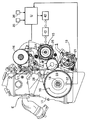
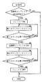
図1〜図3は本発明の一実施例を示すもので、図1は自動車のエンジンの正面図、図2は図1の2部拡大断面図、図3は補機の起動時のオートテンショナの作用を説明するフローチャートである。 1 to 3 show an embodiment of the present invention. FIG. 1 is a front view of an automobile engine, FIG. 2 is an enlarged sectional view of part 2 of FIG. 1, and FIG. 3 is an auto tensioner when starting an auxiliary machine. It is a flowchart explaining the effect | action of.
図1に示すように、自動車のエンジンEはエンジンブロック11の側面に取り付けた補機ブラケット12を備えており、補機ブラケット12に空調用コンプレッサ13、ウオータポンプ14、スタータモータ15、アイドラプーリ16およびオートテンショナ17が支持される。エンジンEのクランクシャフト18に設けたクランクプーリ19と、空調用コンプレッサ13の回転軸20に設けた空調用コンプレッサプーリ21と、ウオータポンプ14の回転軸22に設けたウオータポンププーリ23と、スタータモータ15の回転軸24に設けたスタータモータプーリ25と、回転軸26に設けた前記アイドラプーリ16と、オートテンショナ17に設けたテンショナプーリ27とにベルト28が巻き掛けられる。クランクプーリ19、空調用コンプレッサプーリ21、ウオータポンププーリ23、スタータモータプーリ25、アイドラプーリ16およびテンショナプーリ27の回転方向は矢印で示される。
As shown in FIG. 1, an automobile engine E includes an
オートテンショナ17は伸縮自在なテンショナ本体29を備えており、その上端が支点ピン30を介して補機ブラケット12に枢支される。補機ブラケット12には支点ピン31を介してベルクランク32の中間部が枢支されており、ベルクランク32の一端部がピン33を介してテンショナ本体29の下端に枢支され、ベルクランク32の他端部に回転軸34を介して前記テンショナプーリ27が枢支される。
The
エンジンEを始動するイグニッションスイッチ35と、空調用コンプレッサ13の駆動を指令する空調用スイッチ36と、エンジン回転数を検出するエンジン回転数センサ37とが電子制御ユニットUに接続されており、電子制御ユニットUはオートテンショナ17の作動を制御するとともに、モータコントローラ40およびインバータ41を介してスタータモータ15の作動を制御する。
An
図2に示すように、オートテンショナ17のテンショナ本体29は、補機ブラケット12に接続されるアッパーハウジング51の内周面に、ベルクランク32に接続されるロアハウジング52の外周面を摺動自在に嵌合させてなり、ロアハウジング52に一体に形成したシリンダ53にアッパーハウジング51に一体に形成したピストン54が摺動自在に嵌合する。シリンダ53およびピストン54によって区画された第1液室55と、シリンダ53の外側に区画された第2液室56とがロアハウジング52に形成した第1連通路57および第2連通路58を介して接続されており、第1液室55の全部および第2液室56の一部に液体が封入される。テンショナ本体29が収縮すると第1液室55の容積が縮小し、テンショナ本体29が伸長すると第1液室55の容積が拡大する。
As shown in FIG. 2, the
アッパーハウジング51およびロアハウジング52は第2液室56に収納したスプリング59で相互に離反する方向(つまりテンショナ本体29が伸長する方向)に付勢されており、このスプリング59の弾発力はテンショナプーリ27をベルト28に押し付けて張力を付与する方向に作用する。
The
第1連通路57には円錐状の弁座60および球状の弁体61よりなるチェック弁62が設けられており、このチェック弁62によって第1液室55から第2液室56への液体の移動が阻止され、その逆方向の液体の移動が許容される。第2連通路58には、円錐状の弁座63に向けて球状の弁体64をスプリング65で付勢した制御弁66と、絞り67とが設けられる。制御弁66の開閉を制御するアクチュエータ68は、ソレノイド69と、ソレノイド69により作動するアマチュア70と、アマチュア70と一体に設けられた押圧ロッド71と、アマチュア70を付勢するスプリング72とからなる。
A check valve 62 including a
アクチュエータ68のソレノイド69を消磁すると、スプリング72の弾発力でアマチュア70が左動して押圧ロッド71が弁体64を弁座63から離反させ、制御弁66は強制的に開弁状態に保持される。従って、ソレノイド69の消磁状態では、開弁状態にある制御弁66を介して第1液室55および第2液室56間の双方向への液体の移動が許容される。一方、ソレノイド69を励磁すると、アマチュア70と共に押圧ロッド71が右動して弁体64が弁座63に着座し、制御弁66はチェック弁として機能する。従って、ソレノイド69の励磁状態では、第1液室55から第2液室56への液体の移動が阻止されてテンショナ本体29が収縮不能にロックされ、第2液室56から第1液室55への液体の移動が許容されてテンショナ本体29が伸長可能となる。
When the
次に、上記構成を備えた本発明の実施例の作用を説明する。 Next, the operation of the embodiment of the present invention having the above configuration will be described.
先ず、オートテンショナ17の作用について説明すると、エンジンEの通常の運転時に制御弁66のアクチュエータ68のソレノイド69は消磁状態にあり、アマチュア70および押圧ロッド71がスプリング72の弾発力で左動して弁体64が弁座63から離反することで、制御弁66は強制的に開弁状態に保持される。
First, the operation of the
オートテンショナ17の位置でのベルト28の張力は、エンジンEが加速すると減少し、エンジンEが減速すると増加する。また前記ベルト28の張力は、空調用コンプレッサ13、ウオータポンプ14あるいはスタータモータ15の負荷が増加すると減少し、前記負荷が減少すると増加する。
The tension of the
このようにしてベルト28の張力が増加しようとすると、ベルト28からテンショナプーリ27に作用する荷重がベルクランク32を介してオートテンショナ17のテンショナ本体29に伝達され、テンショナ本体29を収縮させようとする。その結果、スプリング59の弾発力に抗してアッパーハウジング51の内部にロアハウジング52が押し込まれて第1液室55の容積が減少し、チェック弁62が閉弁して第1連通路57が閉塞されることから、第1液室55内の液体は第2連通路58の開弁した制御弁66および絞り67を通過して第2液室56にゆっくりと流入し、ベルト28の張力の増加が抑制される。その際に液体が絞り67を通過することで減衰力が発生する。
When the tension of the
一方、ベルト28の張力が減少しようとすると、ベルト28からテンショナ本体29に伝達される荷重が減少するため、スプリング59の弾発力でアッパーハウジング51の内部からロアハウジング52が押し出されて第1液室55の容積が増加する。このとき、チェック弁62が開弁して第1連通路57が開放されるため、第2液室56内の液体が第1連通路57を経て第1液室55に流入し、テンショナ本体29が伸長してベルト28の張力の減少が抑制される。その際に、第2液室56内の液体の一部が第2連通路58の絞り67を経て第1液室55に流入するが、第2液室56内の液体の大部分は絞りが設けられていない第1連通路57を経て第1液室55に速やかに移動し、テンショナ本体29が伸長する応答性が高められる。
On the other hand, when the tension of the
このように、ベルト28の張力が増減しようとすると、それを補償するようにオートテンショナ17のテンショナ本体29が伸縮することにより、ベルト28の張力を略一定に保持して安定した動力伝達を可能にすることができる。
As described above, when the tension of the
さて、エンジンEを始動すべくスタータモータ15を駆動してスタータモータプーリ25を矢印方向に回転させると、オートテンショナ17の位置でベルト28の張力が急激に増加し、テンショナ本体29が一旦急激に収縮した後にスプリング59の弾発力で急激に伸長するため、ベルト28が暴れて動力伝達が不安定になる虞がある。
Now, when the
そこで本実施例では、エンジンEを始動すべくイグニッションスイッチ35をオンしてスタータモータ15の駆動指令を出力すると、電子制御ユニットUからの指令で制御弁66のアクチュエータ68のソレノイド69が励磁して押圧ロッド71を右動させ、弁体64を弁座63着座可能にして制御弁66をチェック弁として機能させる。その結果、チェック弁62および制御弁66の両方に阻止されて第1液室55内の液体が密封されるため、テンショナ本体29は収縮不能にロックされる。
Thus, in this embodiment, when the
従って、この状態でスタータモータ15を駆動しても、テンショナ本体29は収縮不能にロックされているため、前記ベルト28の暴れを防止してエンジンEをスムーズに始動することができる。そしてエンジン回転数センサ37で検出したエンジン回転数が所定値以上になってエンジンEが完爆したことが確認されると、電子制御ユニットUからの指令で制御弁66のアクチュエータ68のソレノイド69が消磁されてテンショナ本体29のロックが解除される。
Therefore, even if the
ところで、オートテンショナ17を機能させながらエンジンEを運転している間に、負荷の大きい空調用コンプレッサ13を起動すると、その起動時にエンジンEの始動時と同様にベルト28の暴れが発生し、クランクシャフト18から空調用コンプレッサ13への動力伝達が不安定になる可能性がある。そこで本実施例では、図3のフローチャートに示す制御を行って上記問題を解決している。
By the way, if the air-
先ずステップS1で空調用コンプレッサ13を起動すべく空調用スイッチ36がオンされると、ステップS2で電子制御ユニットUからの指令で制御弁66のアクチュエータ68のソレノイド69が励磁し、テンショナ本体29は収縮不能にロックされる。続くステップS3で第1カウンタをインクリメントし、ステップS4で第1カウンタのカウント値が第1所定時間に達すると、ステップS5で空調用コンプレッサ13を起動する。これにより、ベルト28の暴れを防止してクランクシャフト18から空調用コンプレッサ13への動力伝達が不安定になるのを回避することができる。
First, when the
制御弁66のアクチュエータ68のソレノイド69が励磁してから空調用コンプレッサ13が起動するまでに第1所定時間の経過を待つのは、その間にベルト28の張力を高めるためである。即ち、テンショナ本体29が収縮不能にロックされても伸長することは可能であるため、ベルト28の張力が低下する度にスプリング59の弾発力でテンショナ本体29を伸長させてベルト28の張力を増加させることができる。
The reason why the first predetermined time elapses after the
以上のようにして空調用コンプレッサ13が起動すると、ステップS6で第2カウンタをインクリメントし、ステップS7で第2カウンタのカウント値が第2所定時間に達すると、ステップS8でソレノイド69を消磁してテンショナ本体29のロックを解除することで、オートテンショナ17に通常の張力調整機能を発揮させる。空調用コンプレッサ13を起動してからテンショナ本体29のロックを解除するまでに第2所定時間が経過するのを待つのは、空調用コンプレッサ13の起動時の大きな負荷が通常運転時の負荷まで減少するのを待つためである。
When the
以上、本発明の実施例を詳述したが、本発明はその要旨を逸脱しない範囲で種々の設計変更を行うことが可能である。 As mentioned above, although the Example of this invention was explained in full detail, this invention can perform a various design change in the range which does not deviate from the summary.
例えば、本発明の補機は実施例の空調用コンプレッサ13に限定されず、エンジンEの運転中に駆動状態および停止状態が切り替えられる任意の補機であっても良い。
For example, the auxiliary machine of the present invention is not limited to the air-
13 空調用コンプレッサ(補機)
15 スタータモータ
18 クランクシャフト
28 ベルト
29 テンショナ本体
55 第1液室
56 第2液室
59 スプリング
66 制御弁
E エンジン
13 Air conditioning compressor (auxiliary machine)
15
Claims (1)
ベルト(28)の張力に応じて伸縮自在なテンショナ本体(29)と、
テンショナ本体(29)を伸長方向に付勢するスプリング(59)と、
テンショナ本体(29)の収縮に伴って容積が縮小し、伸長に伴って容積が拡大する第1液室(55)と、
第1液室(55)に連通する第2液室(56)と、
第1液室(55)および第2液室(56)間の連通を許容および阻止する制御弁(66)と、
を備えたオートテンショナの制御方法において、
スタータモータ(15)によるエンジン(E)の始動時に制御弁(66)を閉弁して第1液室(55)および第2液室(56)間の連通を阻止する工程と、
エンジン(E)が始動して補機(13)の駆動が可能になったときに制御弁(66)を開弁して第1液室(55)および第2液室(56)間の連通を許容する工程と、
補機(13)を起動する起動信号が出力されたときに制御弁(66)を所定時間だけ閉弁して第1液室(55)および第2液室(56)間の連通を阻止する工程と、
を含むことを特徴とするオートテンショナの制御方法。
In order to apply tension to the belt (28) that transmits driving force among the crankshaft (18) of the engine (E), the auxiliary machine (13), and the starter motor (15),
A tensioner body (29) which can be expanded and contracted according to the tension of the belt (28);
A spring (59) for urging the tensioner body (29) in the extending direction;
A first liquid chamber (55) whose volume decreases as the tensioner body (29) contracts and expands as it expands;
A second liquid chamber (56) communicating with the first liquid chamber (55);
A control valve (66) that allows and blocks communication between the first liquid chamber (55) and the second liquid chamber (56);
In the control method of the auto tensioner provided with
Closing the control valve (66) when starting the engine (E) by the starter motor (15) to prevent communication between the first liquid chamber (55) and the second liquid chamber (56);
When the engine (E) is started and the auxiliary machine (13) can be driven, the control valve (66) is opened to communicate between the first liquid chamber (55) and the second liquid chamber (56). A process of allowing
When a start signal for starting the auxiliary machine (13) is output, the control valve (66) is closed for a predetermined time to prevent communication between the first liquid chamber (55) and the second liquid chamber (56). Process,
A control method for an auto tensioner, comprising:
Priority Applications (1)
| Application Number | Priority Date | Filing Date | Title |
|---|---|---|---|
| JP2004108623A JP4441311B2 (en) | 2004-04-01 | 2004-04-01 | Control method of auto tensioner |
Applications Claiming Priority (1)
| Application Number | Priority Date | Filing Date | Title |
|---|---|---|---|
| JP2004108623A JP4441311B2 (en) | 2004-04-01 | 2004-04-01 | Control method of auto tensioner |
Publications (2)
| Publication Number | Publication Date |
|---|---|
| JP2005291406A true JP2005291406A (en) | 2005-10-20 |
| JP4441311B2 JP4441311B2 (en) | 2010-03-31 |
Family
ID=35324558
Family Applications (1)
| Application Number | Title | Priority Date | Filing Date |
|---|---|---|---|
| JP2004108623A Expired - Fee Related JP4441311B2 (en) | 2004-04-01 | 2004-04-01 | Control method of auto tensioner |
Country Status (1)
| Country | Link |
|---|---|
| JP (1) | JP4441311B2 (en) |
Cited By (1)
| Publication number | Priority date | Publication date | Assignee | Title |
|---|---|---|---|---|
| GB2507985A (en) * | 2012-11-15 | 2014-05-21 | Ford Global Tech Llc | A method and an apparatus for controlling an engine drive belt tensioner system |
-
2004
- 2004-04-01 JP JP2004108623A patent/JP4441311B2/en not_active Expired - Fee Related
Cited By (4)
| Publication number | Priority date | Publication date | Assignee | Title |
|---|---|---|---|---|
| GB2507985A (en) * | 2012-11-15 | 2014-05-21 | Ford Global Tech Llc | A method and an apparatus for controlling an engine drive belt tensioner system |
| US9297445B2 (en) | 2012-11-15 | 2016-03-29 | Ford Global Technologies, Llc | Method for controlling an engine drive belt tensioner system |
| RU2643080C2 (en) * | 2012-11-15 | 2018-01-30 | Форд Глобал Текнолоджиз, Ллк | Method for managing the tension of the drive belt of the engine, the system of tension of the drive belt of the engine and the car containing such system |
| GB2507985B (en) * | 2012-11-15 | 2018-06-13 | Ford Global Tech Llc | A method for controlling an engine drive belt tensioner system |
Also Published As
| Publication number | Publication date |
|---|---|
| JP4441311B2 (en) | 2010-03-31 |
Similar Documents
| Publication | Publication Date | Title |
|---|---|---|
| JP3750801B2 (en) | Hydraulic auto tensioner | |
| KR101555107B1 (en) | Railway car vibration control device | |
| JP3696571B2 (en) | Tension control method in auto tensioner device | |
| JP2010281432A (en) | Hydraulic transmission device for automatic transmission | |
| JP2000265949A (en) | Variable capacity compressor | |
| JP4405424B2 (en) | Control method of power transmission mechanism | |
| JP2007292079A (en) | How to start the engine | |
| JP2010077922A (en) | Cooling fan control device | |
| JP4217183B2 (en) | Auto tensioner device | |
| JP4441311B2 (en) | Control method of auto tensioner | |
| JP5735628B2 (en) | Belt-type continuously variable transmission and vehicle equipped with the same | |
| JP3669696B2 (en) | Engine auto tensioner device | |
| JP4187996B2 (en) | Abnormality detection device for belt mechanism | |
| JP5317867B2 (en) | Belt transmission system | |
| JP4712597B2 (en) | Engine with generator / motor and hydraulic tensioner | |
| JP3815312B2 (en) | Automatic engine stop / restart system for vehicles | |
| JP2003065461A (en) | Control device for electromagnetically driven valve | |
| JP2018040399A (en) | Hydraulic automatic tensioner | |
| JP2005214121A (en) | Control device for automatic tensioner | |
| JP2007107605A (en) | Automatic tensioner | |
| JP4188001B2 (en) | Engine belt tensioner device | |
| JP3958995B2 (en) | Tension control method in auto tensioner device | |
| JP2006266311A (en) | Hydraulic auto tensioner | |
| JP4485935B2 (en) | Fluid damping mechanism of auto tensioner | |
| KR102701728B1 (en) | Method and device for starting an internal combustion engine of a vehicle using a belt drive with a belt starter generator |
Legal Events
| Date | Code | Title | Description |
|---|---|---|---|
| A621 | Written request for application examination |
Effective date: 20061128 Free format text: JAPANESE INTERMEDIATE CODE: A621 |
|
| A977 | Report on retrieval |
Free format text: JAPANESE INTERMEDIATE CODE: A971007 Effective date: 20090826 |
|
| A131 | Notification of reasons for refusal |
Free format text: JAPANESE INTERMEDIATE CODE: A131 Effective date: 20090902 |
|
| A521 | Written amendment |
Free format text: JAPANESE INTERMEDIATE CODE: A523 Effective date: 20091026 |
|
| TRDD | Decision of grant or rejection written | ||
| A01 | Written decision to grant a patent or to grant a registration (utility model) |
Effective date: 20091222 Free format text: JAPANESE INTERMEDIATE CODE: A01 |
|
| A01 | Written decision to grant a patent or to grant a registration (utility model) |
Free format text: JAPANESE INTERMEDIATE CODE: A01 |
|
| A61 | First payment of annual fees (during grant procedure) |
Free format text: JAPANESE INTERMEDIATE CODE: A61 Effective date: 20100108 |
|
| FPAY | Renewal fee payment (prs date is renewal date of database) |
Year of fee payment: 3 Free format text: PAYMENT UNTIL: 20130115 |
|
| R150 | Certificate of patent (=grant) or registration of utility model |
Free format text: JAPANESE INTERMEDIATE CODE: R150 |
|
| LAPS | Cancellation because of no payment of annual fees |