JP2005291362A - Fixing device for structural member - Google Patents
Fixing device for structural member Download PDFInfo
- Publication number
- JP2005291362A JP2005291362A JP2004107152A JP2004107152A JP2005291362A JP 2005291362 A JP2005291362 A JP 2005291362A JP 2004107152 A JP2004107152 A JP 2004107152A JP 2004107152 A JP2004107152 A JP 2004107152A JP 2005291362 A JP2005291362 A JP 2005291362A
- Authority
- JP
- Japan
- Prior art keywords
- engaging
- members
- engagement
- structural
- pair
- Prior art date
- Legal status (The legal status is an assumption and is not a legal conclusion. Google has not performed a legal analysis and makes no representation as to the accuracy of the status listed.)
- Granted
Links
- 239000000463 material Substances 0.000 claims description 77
- 238000003780 insertion Methods 0.000 claims description 34
- 230000037431 insertion Effects 0.000 claims description 34
- 230000000903 blocking effect Effects 0.000 claims description 7
- 238000013459 approach Methods 0.000 claims description 6
- 238000006073 displacement reaction Methods 0.000 claims description 4
- 230000005489 elastic deformation Effects 0.000 claims description 4
- 239000000758 substrate Substances 0.000 description 27
- 238000000926 separation method Methods 0.000 description 12
- 238000000034 method Methods 0.000 description 5
- 238000004519 manufacturing process Methods 0.000 description 3
- 210000004247 hand Anatomy 0.000 description 2
- 229910000639 Spring steel Inorganic materials 0.000 description 1
- 230000004308 accommodation Effects 0.000 description 1
- 229910052782 aluminium Inorganic materials 0.000 description 1
- XAGFODPZIPBFFR-UHFFFAOYSA-N aluminium Chemical compound [Al] XAGFODPZIPBFFR-UHFFFAOYSA-N 0.000 description 1
- 238000006243 chemical reaction Methods 0.000 description 1
- 239000000470 constituent Substances 0.000 description 1
- 230000008878 coupling Effects 0.000 description 1
- 238000010168 coupling process Methods 0.000 description 1
- 238000005859 coupling reaction Methods 0.000 description 1
- 210000003811 finger Anatomy 0.000 description 1
- 229910052751 metal Inorganic materials 0.000 description 1
- 239000002184 metal Substances 0.000 description 1
- 230000000149 penetrating effect Effects 0.000 description 1
- 230000001105 regulatory effect Effects 0.000 description 1
- 210000003813 thumb Anatomy 0.000 description 1
Images

Classifications
-
- F—MECHANICAL ENGINEERING; LIGHTING; HEATING; WEAPONS; BLASTING
- F16—ENGINEERING ELEMENTS AND UNITS; GENERAL MEASURES FOR PRODUCING AND MAINTAINING EFFECTIVE FUNCTIONING OF MACHINES OR INSTALLATIONS; THERMAL INSULATION IN GENERAL
- F16B—DEVICES FOR FASTENING OR SECURING CONSTRUCTIONAL ELEMENTS OR MACHINE PARTS TOGETHER, e.g. NAILS, BOLTS, CIRCLIPS, CLAMPS, CLIPS OR WEDGES; JOINTS OR JOINTING
- F16B7/00—Connections of rods or tubes, e.g. of non-circular section, mutually, including resilient connections
- F16B7/18—Connections of rods or tubes, e.g. of non-circular section, mutually, including resilient connections using screw-thread elements
-
- F—MECHANICAL ENGINEERING; LIGHTING; HEATING; WEAPONS; BLASTING
- F16—ENGINEERING ELEMENTS AND UNITS; GENERAL MEASURES FOR PRODUCING AND MAINTAINING EFFECTIVE FUNCTIONING OF MACHINES OR INSTALLATIONS; THERMAL INSULATION IN GENERAL
- F16B—DEVICES FOR FASTENING OR SECURING CONSTRUCTIONAL ELEMENTS OR MACHINE PARTS TOGETHER, e.g. NAILS, BOLTS, CIRCLIPS, CLAMPS, CLIPS OR WEDGES; JOINTS OR JOINTING
- F16B7/00—Connections of rods or tubes, e.g. of non-circular section, mutually, including resilient connections
- F16B7/04—Clamping or clipping connections
- F16B7/044—Clamping or clipping connections for rods or tubes being in angled relationship
- F16B7/0446—Clamping or clipping connections for rods or tubes being in angled relationship for tubes using the innerside thereof
- F16B7/0473—Clamping or clipping connections for rods or tubes being in angled relationship for tubes using the innerside thereof with hook-like parts gripping, e.g. by expanding, behind the flanges of a profile
-
- F—MECHANICAL ENGINEERING; LIGHTING; HEATING; WEAPONS; BLASTING
- F16—ENGINEERING ELEMENTS AND UNITS; GENERAL MEASURES FOR PRODUCING AND MAINTAINING EFFECTIVE FUNCTIONING OF MACHINES OR INSTALLATIONS; THERMAL INSULATION IN GENERAL
- F16B—DEVICES FOR FASTENING OR SECURING CONSTRUCTIONAL ELEMENTS OR MACHINE PARTS TOGETHER, e.g. NAILS, BOLTS, CIRCLIPS, CLAMPS, CLIPS OR WEDGES; JOINTS OR JOINTING
- F16B7/00—Connections of rods or tubes, e.g. of non-circular section, mutually, including resilient connections
- F16B7/04—Clamping or clipping connections
-
- F—MECHANICAL ENGINEERING; LIGHTING; HEATING; WEAPONS; BLASTING
- F16—ENGINEERING ELEMENTS AND UNITS; GENERAL MEASURES FOR PRODUCING AND MAINTAINING EFFECTIVE FUNCTIONING OF MACHINES OR INSTALLATIONS; THERMAL INSULATION IN GENERAL
- F16B—DEVICES FOR FASTENING OR SECURING CONSTRUCTIONAL ELEMENTS OR MACHINE PARTS TOGETHER, e.g. NAILS, BOLTS, CIRCLIPS, CLAMPS, CLIPS OR WEDGES; JOINTS OR JOINTING
- F16B2200/00—Constructional details of connections not covered for in other groups of this subclass
- F16B2200/67—Rigid angle couplings
-
- F—MECHANICAL ENGINEERING; LIGHTING; HEATING; WEAPONS; BLASTING
- F16—ENGINEERING ELEMENTS AND UNITS; GENERAL MEASURES FOR PRODUCING AND MAINTAINING EFFECTIVE FUNCTIONING OF MACHINES OR INSTALLATIONS; THERMAL INSULATION IN GENERAL
- F16B—DEVICES FOR FASTENING OR SECURING CONSTRUCTIONAL ELEMENTS OR MACHINE PARTS TOGETHER, e.g. NAILS, BOLTS, CIRCLIPS, CLAMPS, CLIPS OR WEDGES; JOINTS OR JOINTING
- F16B37/00—Nuts or like thread-engaging members
- F16B37/04—Devices for fastening nuts to surfaces, e.g. sheets, plates
- F16B37/045—Devices for fastening nuts to surfaces, e.g. sheets, plates specially adapted for fastening in channels, e.g. sliding bolts, channel nuts
-
- Y—GENERAL TAGGING OF NEW TECHNOLOGICAL DEVELOPMENTS; GENERAL TAGGING OF CROSS-SECTIONAL TECHNOLOGIES SPANNING OVER SEVERAL SECTIONS OF THE IPC; TECHNICAL SUBJECTS COVERED BY FORMER USPC CROSS-REFERENCE ART COLLECTIONS [XRACs] AND DIGESTS
- Y10—TECHNICAL SUBJECTS COVERED BY FORMER USPC
- Y10T—TECHNICAL SUBJECTS COVERED BY FORMER US CLASSIFICATION
- Y10T403/00—Joints and connections
- Y10T403/34—Branched
- Y10T403/341—Three or more radiating members
- Y10T403/342—Polyhedral
- Y10T403/343—Unilateral of plane
-
- Y—GENERAL TAGGING OF NEW TECHNOLOGICAL DEVELOPMENTS; GENERAL TAGGING OF CROSS-SECTIONAL TECHNOLOGIES SPANNING OVER SEVERAL SECTIONS OF THE IPC; TECHNICAL SUBJECTS COVERED BY FORMER USPC CROSS-REFERENCE ART COLLECTIONS [XRACs] AND DIGESTS
- Y10—TECHNICAL SUBJECTS COVERED BY FORMER USPC
- Y10T—TECHNICAL SUBJECTS COVERED BY FORMER US CLASSIFICATION
- Y10T403/00—Joints and connections
- Y10T403/46—Rod end to transverse side of member
- Y10T403/4602—Corner joint
Landscapes
- Engineering & Computer Science (AREA)
- General Engineering & Computer Science (AREA)
- Mechanical Engineering (AREA)
- Mutual Connection Of Rods And Tubes (AREA)
- Joining Of Building Structures In Genera (AREA)
- Clamps And Clips (AREA)
- Connection Of Plates (AREA)
Abstract
Description
この発明は、アルミニウム角材等からなる二つの構造材を、それらの側面に形成された係合溝を利用して連結固定するための構造材の固定装置に関する。 The present invention relates to a structural material fixing device for connecting and fixing two structural materials made of aluminum squares or the like using engagement grooves formed on their side surfaces.
従来のこの種の固定装置としては、下記特許文献1に記載されたものがある。この固定装置は、一端部と他端部とが二つの構造材の各側面にそれぞれ突き当てられた当接部材と、この当接部材と二つの構造材との間に配置された第1、第2係合部材と、この第1、第2係合部材に、一端部と他端部とが係合溝の幅方向へ移動可能に、かつ構造材から離間する方向へ移動不能に設けられた雌ねじ部材と、当接部材を貫通して雌ねじ部材に螺合された雄ねじ部材とを備えている。第1係合部材の二つの構造材に隣接する二つの側部、及び第2係合部材の二つの構造材に隣接する二つの側部には、係合部がそれぞれ形成されている。 As a conventional fixing device of this type, there is one described in Patent Document 1 below. The fixing device includes a contact member whose one end and the other end are respectively abutted against the side surfaces of the two structural members, and a first member disposed between the contact member and the two structural members. The second engagement member and the first and second engagement members are provided with one end portion and the other end portion movable in the width direction of the engagement groove and immovable in a direction away from the structural material. And a male screw member that penetrates the contact member and is screwed to the female screw member. Engaging portions are respectively formed on two side portions adjacent to the two structural members of the first engaging member and on two side portions adjacent to the two structural members of the second engaging member.
このように構成された固定装置によって二つの構造材を固定する場合には、まず第1、第2係合部材を互いに接近移動させ、それぞれの係合部を係合溝の両側壁面の開放側端部にそれぞれ形成された突出部間から係合溝内に挿入する。その後、当接部材を貫通して雌ねじ部材に螺合された雄ねじ部材を締め付ける。すると、第1、第2係合部材が互いに離間移動させられ、各係合部材の係合部が係合溝の突出部と対向する。その後、雄ねじ部材をさらに締め付けると、当接部材の両端部が各構造材に突き当てられるとともに、第1、第2係合部材の各係合部が二つの構造材の係合溝の各突出部にそれぞれ突き当てられる。これにより、一対の構造材が固定される。 When two structural members are fixed by the fixing device configured as described above, first, the first and second engaging members are moved closer to each other, and the respective engaging portions are opened on the open side surfaces of both side walls of the engaging groove. It inserts in an engaging groove from between the protrusion parts each formed in the edge part. Thereafter, the male screw member that passes through the contact member and is screwed into the female screw member is tightened. Then, the first and second engaging members are moved away from each other, and the engaging portion of each engaging member faces the protruding portion of the engaging groove. Thereafter, when the male screw member is further tightened, both end portions of the abutting member are abutted against the respective structural members, and the respective engaging portions of the first and second engaging members are protruded from the engaging grooves of the two structural members. Each part is abutted. Thereby, a pair of structural material is fixed.
上記従来の固定装置においては、第1、第2係合部材の各係合部が係合溝に挿入されただけの状態では各係合部が係合溝から脱出可能である。このため、雄ねじ部材を雌ねじ部材に螺合させる際には、第1、第2係合部材が係合溝から脱落するのを防止するために、第1、第2係合部材を手で保持していなければならない。したがって、従来の固定装置で一対の構造材を固定する際には、一方の手で第1、第2係合部材を保持しつつ、他方の手で雄ねじ部材を雌ねじ部材に螺合させなければならず、螺合作業が行いにくいという問題があった。 In the above-described conventional fixing device, each engaging portion can be removed from the engaging groove in a state where each engaging portion of the first and second engaging members is merely inserted into the engaging groove. Therefore, when the male screw member is screwed into the female screw member, the first and second engagement members are held by hand in order to prevent the first and second engagement members from falling off the engagement grooves. Must be. Therefore, when fixing a pair of structural members with a conventional fixing device, the first and second engaging members must be held with one hand and the male screw member must be screwed into the female screw member with the other hand. In other words, there was a problem that the screwing work was difficult to perform.
この発明は、上記の問題を解決するために、それぞれの一側面に、両側壁面の開放側端部に互いに接近するように突出する突出部を有する係合溝が形成された一対の構造材を、両方の構造材の上記係合溝が形成された一側面どうしが交差するように一方の構造材の上記一側面に他方の構造材の端面を突き当てた状態で固定するための構造材の固定装置において、上記一対の構造材の各一側面に突き当てられる当接部材と、上記一対の構造材の各係合溝の一方の側壁面に形成された各突出部に上記係合溝の内側から外側へ脱出不能にそれぞれ係合可能である二つの係合部が、上記一対の構造材側の各側部にそれぞれ設けられた第1係合部材と、上記第1係合部材に対し上記係合溝の幅方向に対向して配置され、上記一対の構造材の各係合溝の他方の側壁面に形成された各突出部に上記係合溝の内側から外側へ脱出不能にそれぞれ係合可能である二つの係合部が、上記一対の構造材側の各側部にそれぞれ設けられた第2係合部材と、上記第1、第2係合部材に上記一対の構造材の各一側面から離間する方向へ移動不能に設けられた雌ねじ部材と、上記当接部材を貫通して上記雌ねじ部材に螺合された雄ねじ部材とを備え、上記第1、第2係合部材が、それぞれの係合部が上記突出部の対向面間を通って上記係合溝に対して出没可能になる挿通位置と、それぞれの係合部が上記突出部に対し上記係合溝の内側から外側へ脱出不能に係合可能である係合位置との間を上記係合溝の幅方向へ接近離間変位可能とされ、上記第1、第2係合部材間には、上記第1、第2係合部材を互いに離間する方向へ付勢してそれぞれの係合部を上記係合位置に変位させる付勢手段が設けられ、上記雄ねじ部材が締め付けられると、上記当接部材が上記一対の構造材の各一側面に突き当てられるとともに、上記係合位置に位置している上記第1、第2係合部材の各係合部が上記一対の構造材の各突出部に上記係合溝の内側から外側へ向かって突き当てられ、それによって上記一対の構造材を互いに固定することを特徴としている。
この場合、上記第1、第2係合部材を、少なくとも上記挿通位置と上記係合位置との間において上記係合溝の幅方向へ接近離間変位可能に保持する保持部材をさらに備えていることが望ましい。
上記保持部材が弾性変形可能とされ、上記保持部材の弾性変形によって上記第1、第2係合部材が上記係合位置から上記挿通位置まで接近変位され、上記保持部材が弾性的に復帰変形することによって上記第1、第2係合部材が上記挿通位置から上記係合位置へ離間変位させられるよう、上記保持部材が上記付勢手段として兼用されていることが望ましい。
上記係合溝の幅方向における上記雌ねじ部材の一端部と他端部とが、上記一対の係合部材の上記一対の構造材から離間した各側部にそれぞれ一体に設けられ、上記雌ねじ部材が設けられた側部と上記係合部が設けられた側部との間における上記第1、第2係合部材の中間部が、上記第1、第2係合部材の係合部を上記係合位置から上記挿通位置まで接近変位させることができるよう、弾性変形可能とされ、当該中間部が弾性的に復帰変形することによって上記第1、第2係合部材が上記挿通位置から上記係合位置へ離間変位させられるよう、上記中間部が上記付勢手段として兼用されていることが望ましい。
上記当接部材には、上記一対の構造材の各係合溝にその幅方向へ移動不能に嵌り込む位置決め部が設けられていることが望ましい。
上記当接部材には、上記係合位置に位置している上記一対の係合部材間に入り込むことによって上記一対の係合部材が上記挿通位置まで接近変位するのを阻止する変位阻止部が設けられていることが望ましい。
In order to solve the above-described problem, the present invention provides a pair of structural members each having an engaging groove having a protruding portion protruding so as to approach the open end portions of both side wall surfaces on one side surface. , A structural material for fixing in a state in which the end surface of the other structural material is abutted against the one side surface of one structural material so that the one side surfaces in which the engaging grooves of both structural materials are formed intersect each other In the fixing device, a contact member that is abutted against each side surface of the pair of structural members, and a protrusion formed on one side wall surface of each engagement groove of the pair of structural members are provided with the engagement grooves. Two engagement portions that can be engaged from the inside to the outside so as not to escape are respectively provided to the first engagement member provided on each side portion of the pair of structural members, and the first engagement member The engaging grooves are arranged opposite to each other in the width direction, and the engaging grooves of the pair of structural members Two engaging portions that can be engaged with the respective protruding portions formed on the side wall surfaces of the pair of structural members so as not to escape from the inside to the outside of the engaging grooves are respectively provided on the side portions of the pair of structural members. A second engaging member, a female screw member provided on the first and second engaging members so as not to move in a direction away from each side surface of the pair of structural members, and the contact member. A male screw member threadedly engaged with the female screw member, and the first and second engaging members can protrude and retract with respect to the engaging groove with the respective engaging portions passing between the opposing surfaces of the protruding portion. Between the insertion position and the engagement position at which each engaging portion can be engaged with the protruding portion from the inside to the outside of the engaging groove so as not to escape. The first and second engaging members are separated from each other between the first and second engaging members. When the male screw member is tightened, the abutting member pushes against each side surface of the pair of structural members. Each of the engaging portions of the first and second engaging members positioned at the engaging position protrudes from the inside of the engaging groove to the outside of the pair of structural members. It is characterized in that the pair of structural members are fixed to each other.
In this case, a holding member is further provided to hold the first and second engaging members so that they can be moved toward and away from each other in the width direction of the engaging groove at least between the insertion position and the engaging position. Is desirable.
The holding member can be elastically deformed, and the first and second engaging members are moved closer to the insertion position from the engaging position by the elastic deformation of the holding member, and the holding member is elastically deformed to return. Accordingly, it is preferable that the holding member is also used as the urging means so that the first and second engaging members are displaced away from the insertion position to the engaging position.
One end and the other end of the female screw member in the width direction of the engagement groove are integrally provided on each side portion of the pair of engagement members spaced apart from the pair of structural members, and the female screw member is An intermediate portion of the first and second engaging members between the provided side portion and the side portion provided with the engaging portion is configured to connect the engaging portions of the first and second engaging members to the engaging portion. The first and second engaging members are engaged with the first and second engagement members from the insertion position by elastically deforming the intermediate portion so that the first and second engagement members can be elastically deformed so as to be able to approach and displace from the insertion position to the insertion position. It is desirable that the intermediate portion is also used as the urging means so as to be displaced to a position.
The contact member is preferably provided with a positioning portion that fits in the engagement groove of the pair of structural members so as not to move in the width direction.
The abutment member is provided with a displacement blocking portion that prevents the pair of engagement members from being displaced close to the insertion position by entering between the pair of engagement members positioned at the engagement position. It is desirable that
上記特徴構成を有するこの発明によれば、第1、第2係合部材を挿通位置に接近移動させることにより、第1、第2係合部材の係合部を係合溝内にその二つの突出部間から挿入することができる。係合部を係合溝内に挿入した後、第1、第2係合部材を自由に移動することができる状態にすると、第1、第2係合部材が付勢手段の付勢力によって係合位置まで離間移動させられる。この状態では、第1、第2係合部材の各係合部が係合溝内において突出部と対向するので、係合部が係合溝から脱出不能になる。したがって、第1、第2係合部を手で保持しておく必要がない。よって、雄ねじ部材を雌ねじ部材に螺合させる際には両手を使用することができ、螺合作業を容易に行うことができる。 According to this invention having the above-described characteristic configuration, the first and second engaging members are moved closer to the insertion position, whereby the engaging portions of the first and second engaging members are moved into the engaging grooves. It can be inserted from between the protrusions. After the engaging portion is inserted into the engaging groove, the first and second engaging members are engaged by the urging force of the urging means when the first and second engaging members are allowed to move freely. It is moved away to the alignment position. In this state, each engaging portion of the first and second engaging members faces the protruding portion in the engaging groove, so that the engaging portion cannot escape from the engaging groove. Therefore, it is not necessary to hold the first and second engaging portions by hand. Therefore, when screwing the male screw member into the female screw member, both hands can be used, and the screwing operation can be easily performed.
以下、この発明を実施するための最良の形態を、図面を参照して説明する。
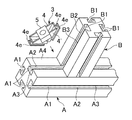
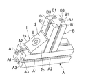
図1〜図10は、この発明の第1実施の形態を示す。まず、この実施に係る構造材の固定装置が固定すべき二つの構造材A,Bについて説明すると、構造材Aは、図8〜図10に示すように、断面正方形の棒状に形成されている。構造材Aの各側面の中央部には、構造材Aの長手方向に延びる係合溝A1が形成されている。係合溝A1の両側壁面の開放側端部には、互いに接近するように、係合溝A1の幅方向内側に向かってへ突出する突出部A2,A3が形成されている。これにより、係合溝A1が断面T字状に形成されている。構造材Aは、断面長方形状、断面T字状、その他の形状に形成してもよい。また、構造材Aの各側面に係合溝A1をそれぞれ形成することなく、一つの側面にのみ係合溝A1を形成してもよい。さらに、係合溝A1の突出部A1,A2は、係合溝A1の開放側端部から低部側に向かって若干離れた箇所に形成してもよい。構造材Bは、構造材Aと同一の断面形状に形成されている。したがって、係合溝B1も係合溝A1と同一の断面形状に形成されており、突出部A2,A3に対応する突出部B2,B3を有している。勿論、構造材Bも、構造材Aと同様に断面長方形状、断面T字状、その他の形状にしてもよい。また、構造材B及び係合溝B1は、構造材A及び係合溝A1とそれぞれ異なる形状にしてもよい。
The best mode for carrying out the present invention will be described below with reference to the drawings.
1 to 10 show a first embodiment of the present invention. First, the two structural materials A and B to be fixed by the structural material fixing device according to this embodiment will be described. The structural material A is formed in a bar shape having a square cross section as shown in FIGS. . An engaging groove A <b> 1 extending in the longitudinal direction of the structural material A is formed at the center of each side surface of the structural material A. Projection portions A2 and A3 projecting inward in the width direction of the engagement groove A1 are formed at the open end portions of both side wall surfaces of the engagement groove A1 so as to approach each other. As a result, the engagement groove A1 is formed in a T-shaped cross section. The structural material A may be formed in a rectangular cross section, a T cross section, or other shapes. Further, the engaging groove A1 may be formed only on one side without forming the engaging groove A1 on each side of the structural material A. Further, the protrusions A1 and A2 of the engagement groove A1 may be formed at locations slightly apart from the open end of the engagement groove A1 toward the low side. The structural material B is formed in the same cross-sectional shape as the structural material A. Therefore, the engagement groove B1 is also formed in the same cross-sectional shape as the engagement groove A1, and has protrusions B2 and B3 corresponding to the protrusions A2 and A3. Of course, the structural material B may have a rectangular cross-section, a T-shaped cross-section, and other shapes as with the structural material A. Further, the structural material B and the engagement groove B1 may have different shapes from the structural material A and the engagement groove A1.
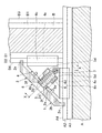
構造材Aの一側面A4に構造材Bの一端面が突き当てられている。この場合、構造材Aと構造材Bとは互いに直交するように突き当てられている。したがって、構造材Aの一側面A4と構造材Bの一側面B4も互いに直交している。しかも、構造材A,Bは、一側面A4,B4の幅方向において同一位置に位置するように配置されている。したがって、係合溝A1,B1もその幅方向において同一位置に位置している。 One end surface of the structural material B is abutted against one side surface A4 of the structural material A. In this case, the structural material A and the structural material B are abutted so as to be orthogonal to each other. Therefore, one side surface A4 of the structural material A and one side surface B4 of the structural material B are also orthogonal to each other. Moreover, the structural materials A and B are disposed so as to be located at the same position in the width direction of the one side surfaces A4 and B4. Therefore, the engagement grooves A1 and B1 are also located at the same position in the width direction.
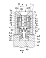
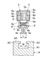
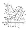
次に、構造材A,Bを固定するための構造材の固定装置1について説明すると、図1〜図3に示すように、固定装置1は、当接部材2と固定ユニット3とを有している。そして、当接部材2を貫通して固定ユニット3のナット(雌ねじ部材)6に螺合するボルト(雄ねじ部材)8を締め付けることにより、固定装置1が構造材A,Bを固定するようになっている。
Next, the structural material fixing device 1 for fixing the structural materials A and B will be described. As shown in FIGS. 1 to 3, the fixing device 1 includes a
図1〜図3及び図6に示すように、当接部材2は、天板部2aと、この天板部2aの両側部(構造材A,Bの幅方向における両側部)に一体に設けられた一対の側板部2b,2cとを有している。天板部2aは、平板状をなしており、構造材A,Bに対して同一角度だけ傾斜した状態で配置されている。この実施の形態の場合、構造材A,Bのなす角が90°であるので、天板部2aは構造材A,Bに対して45°だけ傾斜している。勿論、構造材A,Bのなす角が90°以外の角度の場合には、天板部2の構造材A,Bに対する角度は、45°以外の角度になる。天板部2Aの長手方向の両端部は、構造材A,Bの各一側面A4,B4に突き当てられている。天板部2aの中央部には、天板部2aを貫通するボルト座2dが形成されている。天板部2aの両端部の幅方向における中央部には、構造材A,B側へ向かって突出する位置決め突起(位置決め部)2eがそれぞれ形成されている。位置決め突起2eの幅は、係合溝A1,B1の突出部A2,A3;B2,B3の間隔とほぼ同一に設定されている。そして、一方の位置決め突起2eが係合溝A1の突出部A2,A3間に挿入されるとともに、他方の位置決め突起2eが係合溝B1の突出部B2,B3間に挿入することにより、当接部材2が構造材A,Bに対してその幅方向(係合溝の幅方向)に位置決めされている。天板部2aの構造材A,B側を向く内面には、一対の阻止板部(変位阻止部)2f,2fが設けられている。各阻止板2fは、ボルト座2dに対して天板部2aの一端側と他端側とに若干離れた箇所にそれぞれ配置されている。
As shown in FIGS. 1 to 3 and 6, the
一対の側板部2b,2cは、天板部2aを斜辺とする直角三角形の平板状に形成されており、構成材A,Bの幅方向に互いに離間対向して配置されている。したがって、当接部材2の内部には、天板部2aと一対の側板部2b,2cとによって断面直角三角形の収容空間Sが形成されている。各側板部2b,2cの互いに直交する2つの側面は、構造材A,Bの一側面A4,B4にそれぞれ突き当てられている。
The pair of
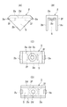
図2及び図3に示すように、固定ユニット3は、構造材A,Bの固定時には、当接部材2と構造材A,Bとの間に配置されている。特に、この実施の形態では、当接部材2の収容空間S内に収容されている。固定ユニット3は、図2〜図5に示すように、第1、第2係合部材4,4′、保持部材5、ナット6及びコイルばね(付勢手段)7を有しており、全体を一体的に取り扱うことができるように組み立てられている。
As shown in FIGS. 2 and 3, the fixing
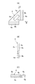
第1係合部材4は、図1〜図5及び図7に示すように、基板部4aとこの基板部4aに一体に形成された第1、第2係合部(係合部)4b,4cとを有している。基板部4aは、直角三角形の直角をなす角部が切り欠かれた形状をなす平板として形成されており、当接部材2の一方の側板部2bの近傍に当該側板部2bと平行に配置されている。しかも、基板部4aは、斜辺となる側部が当接部材2の天板部2aと平行になるように配置されている。したがって、基板部4aの互いのなす角度が直角である二つの側部は、構造材A,Bと平行になっている。基板部4aの中央部には、長方形状をなす保持孔4dが形成されている。この保持孔4dは、基板部4aを貫通しており、基板部4aの斜辺となる側部と平行に延びている。第1、第2係合部4b,4cは、基板部4aの互いのなす角度が直角である二つの側部にそれぞれ形成されている。第1係合部4bは、基板部4aから離れた側部が係合溝A1に挿脱可能に挿入されている。第1係合部4bの係合溝A1内に挿入された側部には、側板部2b側に突出する係合突条4eが形成されている。第2係合部4cは、係合溝B1に挿入されている。第2係合部4cは、係合溝A1,B1が互いに同一形状をなしているので、第1係合部4bと同一形状に形成されている。したがって、第2係合部4cの係合溝B1に挿入された側部には、側板部2b側に突出する係合突条4eが形成されている。
As shown in FIGS. 1 to 5 and 7, the
第2係合部材4′は、当接部材2の他方の側板部2cの近傍に当該側板部2cと平行に配置されており、係合溝A1,B1の2等分線L(図3参照)に関して第1係合部材4と対称に形成され、かつ配置されている。そこで、第2係合部材4′については、第1係合部材4と同様な部分に同一符号を付してその説明を省略する。
The second engagement member 4 'is disposed in the vicinity of the other
第1、第2係合部材4,4′の各保持孔4d,4dには、係合溝A1,B1の幅方向におけるナット6の一端部と他端部とが同方向へ移動可能、かつ保持孔4dの長手方向及び天板部2aと直交する方向(一側面A4,B4のなす角を2等分する線が延びる方向)へ移動不能に挿入されている。ナット6の中央部には、ねじ孔6aが形成されている。このねじ孔6aは、その軸線を当接部材2のボルト座2dの軸線と一致させて形成されている。
In each holding
第1、第2係合部材4,4′は、保持部材5によって係合溝A1,B1の幅方向へ移動可能に保持されている。すなわち、保持部材5は、金属製の比較的薄い板材からなるものであり、図2〜図5、図8及び図9に示すように、基板部5aと、この基板部5aの両側部に基板部5aと一体に設けられた規制板部5b,5cとを有している。基板部5aは、第1、第2係合部材4,4′の斜辺をなす側面の中央部に第1、第2係合部材4,4′の対向方向(係合溝A1,B1の幅方向)へ相対摺動可能に接触させられている。規制板部5b,5cは、基板部5aから側面A4,B4の交差部に向かって直角に突出している。規制板部5b,5cは、第1、第2係合部材4,4′の基板部4a,4aの外側に配置され、各基板部4a,4aとそれぞれ対向している。規制板部5b,5cは、第1、第2係合部材4,4′の保持孔4d,4dを外側から覆っている。これによって、ナット6が保持孔4dから抜け落ちることが防止されている。しかも、係合溝A1,B1の幅方向におけるナット6の幅は、規制板部5b,5cの間隔とほぼ同一になっている。したがって、ナット6は、保持部材5によって係合溝A1,B1の幅方向に位置固定されており、第1、第2係合部材4,4′に対して同方向へ相対移動する。規制板部5b,5cの各先端部には、互いに接近するように突出する挟持部5dが形成されている。規制板部5bに形成された挟持板部5dは、第1係合部材4の保持孔4dの係合部4b側の内面とナット6との間に摺動可能に挿入されており、規制板部5cに形成された挟持板部5dは、第2係合部材4′の保持孔4dの係合部4b側の内面とナットとの間に摺動可能に挿入されている。この結果、第1、第2係合部材4,4′が保持部材の基板部5aと挟持板部5d,5dによりナット6を介して係合溝A1,B1の幅方向へ移動可能に支持されている。
The first and second engaging
第1、第2係合部材4,4′の基板部4a,4a間には、コイルばね7が設けられている。コイルばね7は、圧縮状態で設けられており、第1、第2係合部材4,4′を互いに離間する方向に付勢している。この付勢力によって第1、第2係合部材4,4′が保持部材5の規制板部5b,5cにそれぞれ押し付けられている(図4参照)。以下、このときの第1、第2係合部材4,4′の位置を最大離間位置という。その一方、第1、第2係合部材4,4′は、コイルばね7の付勢力に抗して互いに接近移動可能であり、図5に示すように、第1係合部材4の第1、第2係合部4b,4cと第2係合部材4′の第1、第2係合部4b,4cとがそれぞれ突き当たるまで接近移動可能である。このときの第1、第2係合部材4,4′の位置が挿通位置である。したがって、第1、第2係合部材4,4′は、保持部材5により係合溝A1,B1の幅方向へ挿通位置と最大離間位置との間を移動可能に保持されている。第1、第2係合部材4,4′は、最大離間位置に位置しているときは勿論のこと、挿通位置に位置しているときにも保持部材5の基板部5aと挟持板部5d,5dによって常時挟持されている。これにより、第1、第2係合部材4,4′、保持部材5、ナット6及びコイルばね7が、常に一体に取り扱うことができるようにユニット化されているのである。
A
図5に示すように、第1、第2係合部材4,4′が挿通位置に位置しているときには、第1、第2係合部材4,4′の係合突条4e,4eの先端面間の間隔Lが係合溝A1,B1の突出部A2,A3;B2,B3の先端面間の間隔Wより狭くなっている。したがって、係合突条4e,4eは、突出部A2,A3;B2,B3の間から係合溝A1;B1内に挿入可能である。係合突条4e,4eが突出部A2,A3;B2,B3間を通り抜けて係合溝A1;B1に入り込んだ後、第1、第2係合部材4,4′を自由に移動し得る状態にすると、第1、第2係合部材4,4′はコイルばね7の付勢力によって互いに離間する方向(係合溝A,Bの幅方向)へ移動させられる。そして、第1、第2係合部材4,4′が最大離間位置の直前の位置まで移動すると、第1係合部材4は、その第1、第2係合部4b,4cが係合溝A1,B1の突出部A2,B2の先端面(突出部A2,B2の対向面)にそれぞれ突き当たることによって停止させられ、第2係合部材4′は、その第1、第2係合部4b,4cが係合溝A1,B1の突出部A3,B3の先端面にそれぞれ突き当たることによって停止させられる。このときの第1、第2係合部材4,4′の位置が係合位置である。
As shown in FIG. 5, when the first and second engaging
したがって、この実施の形態では、保持部材5が、挿通位置と係合位置とを内部に含む挿通位置と最大離間位置との間において第1、第2係合部材4,4′を係合溝A1,B1の幅方向へ移動可能に保持している。必ずしもこのようにする必要はなく、最大離間位置を係合位置としてもよい。その場合には、第1係合部材4の第1、第2係合部4b,4cが係合溝A1,B1の突出部A2,B2にそれぞれ突き当たるとともに、第2係合部材4′の第1、第2係合部4b,4cが係合溝A1,B1の突出部A3,B3にそれぞれ突き当たると同時に、第1、第2係合部材4,4′が最大離間位置に達するようにしてもよく、第1係合部材4の第1、第2係合部4b,4cが係合溝A1,B1の突出部A2,B2に、第2係合部材4′の第1、第2係合部4b,4cが係合溝A1,B1の突出部A3,B3にそれぞれ突き当たる以前に、第1、第2係合部材4,4′が最大離間位置に達するようにしてもよい。ただし、いずれの場合において、第1、第2係合部材4,4′が係合位置に位置すると、図2及び図3に示すように、第1係合部材4の係合突条4e,4eが突出部A2,B2の内側の面(図2及び図3において下側の面)と対向するとともに、第2係合部材4′の係合突条4e,4eが突出部A3,B3の内側の面と対向する。この結果、第1、第2係合部材4,4′の各第1、第2係合部4b,4cが係合溝A1,B1から脱出不能になり、係合部材4,4′が構造材A,Bに離脱不能に保持される。
Therefore, in this embodiment, the holding
ナット6のねじ孔6aには、当接部材2のボルト座2d及び保持部材5の基板部5aを貫通したボルト8のねじ部8aが螺合されている。このボルト8の頭部8bは、ボルト座
2dに突き当たっている。したがって、第1、第2係合部材4,4′が図2に示す係合位置に位置している状態において、ボルト8を締め付けると固定ユニット3が当接部材2の天板部2aに接近する方向(図2及び図3において上方)方向へ移動させられる。ボルト8をさらに締め付けると、第1係合部材4の係合突条4e,4eが係合溝A1,B1の突出部A2、B2にそれぞれ突き当たるとともに、第2係合部材4′の係合突条4e,4eが係合溝A1,B1の突出部A3,B3にそれぞれ突き当たる。また、その反力によって当接部材2の天板部2aの一端部、側板部2b,2cの一側部が構造材Aの一側面A4に突き当てられるとともに、当接部材2の天板部2aの他端部、側板部2b,2cの他側部が構造材Bの一側面B4に突き当てられる。これにより、構造材A,Bが固定装置1を介して固定されている。
A threaded
上記構成を有する構造材の固定装置1によって構造材A,Bを固定する場合には、図5及び図8に示すように、まず固定ユニット3の第1、第2係合部材4,4′をコイルばね7の付勢力に抗して接近移動させ、挿通位置に位置させる。これは、例えば親指と人差し指とで第1、第2係合部材4,4′を持って接近移動させることによって行うことができる。次に、固定ユニット3を構造材A,Bに接近移動させ、第1、第2係合部材4,4′の第1係合部4b、4bの各係合突条4e,4eを突出部A2,A3間から係合溝A1内に挿入するとともに、第1、第2係合部材4,4′の第2係合部4c,4cの各係合突条4e,4eを突出部B2,B3間から係合溝B1内に挿入する。その後、第1、第2係合部材4,4′から手を離して自由に移動できるようにすると、第1、第2係合部材4,4′がコイルばね7によって係合位置まで移動させられて停止する。すると、4つの係合突条4eが突出部A2,A3,B2,B3と対向するので、図9に示すように、固定ユニット3が構造材A,Bに離脱不能に保持される。
When the structural materials A and B are fixed by the structural material fixing device 1 having the above-described configuration, first and second engaging
次に、収容空間S内に固定ユニット3が入るようにして当接部材2の天板部2aの両端部、及び側板部2b,2cを構造材A,Bの一側面A4,B4にぞれぞれ突き当てる。このとき、当接部材2の位置決め突起2e,2eが係合溝A1の突出部A2,A3間、及び係合溝B1の突出部B2,B3間に入り込むことにより、係合溝A1,B1の幅方向における当接部材2の位置決めが成される。しかも、当接部材2を構造材A,Bの一側面A4,B4に突き当てた状態では、当接部材2の阻止板部2f、2fが係合位置に位置している第1、第2係合部材4,4′の基板部4a,4a間に入り込む。阻止板部2fの幅(係合溝A1,B1の幅方向における幅)は、基板部4a,4aの間隔とほぼ等しく設定されている。したがって、当接部材2を構造材A,Bの一側面A4,B4に突き当てると、第1、第2係合部材4,4′がほとんど接近移動不能になる。その後、ボルト座2dからボルト8のねじ部8aを挿通し、ナット6のねじ孔6aに螺合させる。このとき、位置決め突起2e,2eによって係合溝A1,A2の幅方向における当接部材2の位置決めが行われ、その結果ボルト座2dとねじ孔6aとの互いの軸線が一致させられているので、ボルト8をナット6に容易に螺合させることができる。その後、ボルト8を締め付ける。これにより、構造材A,Bが固定される(図10参照)。
Next, the both ends of the
構造材A,Bの固定を解除する場合には、上記と逆の手順を行えばよい。すなわち、ボルト8を緩めてナット6から取り外す。次に、当接部材2を取り外し、固定ユニット3を露出させる。その後、第1、第2係合部材4,4′を挿通位置まで接近移動させる。そして、固定ユニット3を構造材A,Bから取り外す。
In order to release the fixing of the structural materials A and B, a procedure reverse to the above may be performed. That is, the
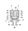
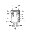
図11は、固定ユニット3に代えて用いられる固定ユニット3Aを示している。この固定ユニット3Aにおいては、保持部材5に代えて保持部材5Aが用いられている。保持部材5Aは、ばね鋼等の弾性を有する板材によって構成されており、規制板部5b,5cが第1、第2係合部材4,4′の基板部4a,4aに固定されている。第1、第2係合部材4,4′は、保持部材5Aが弾性変形することによって第1係合部材4の第1、第2係合部4b,4cと第2係合部材4′の第1、第2係合部4b,4cが互いに突き当たった想像線で示す挿通位置と、実線で示す最大離間位置との間を移動可能になっている。保持部材5Aは、第1、第2係合部材4,4′が最大離間位置に位置しているときに弾性変形のない自然状態になっており、第1、第2係合部材4,4′が挿通位置に位置しているときには、第1、第2係合部材4,4′の最大離間位置から挿通位置までの変位量に対応して弾性変形する。その結果、第1、第2係合部材4,4′が挿通位置に位置しているときには、それらを最大離間位置に戻すように付勢する。これから明かなように、保持部材5Aは、付勢手段として兼用されている。なお、挿通位置及び最大離間位置と係合位置との関係は、上記の実施の形態と同様の関係に設定されている。
FIG. 11 shows a
このように構成された固定ユニット3Aを用いた場合には、コイルばね7が不要であるので、その分だけ製造の手間及び組立工数を減らすことができ、それによって固定ユニット3Aの製造費を低減することができる。
When the fixed
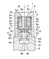
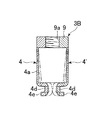
図12は、固定ユニット3に代えて用いられる固定ユニット3Bを示している。この固定ユニット3Bにおいては、第1、第2係合部材4,4′の天板部2aと対向する側部(構造材A,Bから離間した側部;図10において上側部)に、雌ねじ孔9aを有する雌ねじ部(雌ねじ部材)9の一端部と他端部とが一体に一体に設けられている。換言すれば、第1、第2係合部材4,4′が雌ねじ部9を介して一体に形成されているのである。雌ねじ部9は、上記実施の形態のナット6に相当するものであり、雌ねじ孔9aにはボルト8が螺合される。第1、第2係合部材4,4′の基板部4a,4a(雌ねじ部9と第1、第2係合部4b,4c間に位置する中間部)は、薄肉に形成されており、それによって第1、第2係合部材4,4′の第1係合部4b,4b(第2係合部4c,4c)が互いに接近離間する方向へ弾性変形可能になっている。基板部4aは、それに外力が作用しない自然状態になっているとき、第1係合部4b及び第2係合部4cを上記実施の形態における最大離間位置に位置させる。しかも、基板部4aは、第1係合部4b,4bどうしおよび第2係合部4c,4cどうしが互いに突き当たって挿通位置に達するまで弾性変形可能である。したがって、基板部4aは、弾性的に復帰変形することにより、係合溝A1,B1に挿入された第1、第2係合部4b,4cを係合位置まで移動させることができる。これから明かなようにこの固定ユニット3Bにおいては、第1、第2係合部材4,4′の各基板部4A,4Aが第1、第2係合部4,4′を挿通位置から係合位置まで移動させるための付勢手段として兼用されている。
FIG. 12 shows a
図13は、固定ユニット3に代えて用いられる固定ユニット3Cを示している。この固定ユニット3Cは、上記固定ユニット3から保持部材5を省いたものであり、その他は固定ユニット3と同様に構成されている。したがって、この固定ユニット3Cは、第1、第2係合部材4,4′、ナット6及びコイルばね7がユニットとして組み立てられているが、組立状態を維持するものがないので、指等によって組立状態に維持する必要がある反面、保持部材5が不要であるので、その分だけ固定ユニット3Cの製造費を低減することができる。なお、コイルばね7が自然状態になっているとき、第1、第2係合部材4,4′は、最大離間位置に位置している。コイルばね7の両端部を第1、第2係合部材4,4′に結合することにより、コイルばね7を保持部材5として兼用することも可能である。
FIG. 13 shows a
A 構造材
A1 係合溝
A2 突出部
A3 突出部
A4 一側面
B 構造材
B1 係合溝
B2 突出部
B3 突出部
B4 一側面
1 構造材の固定装置
2 当接部材
2e 位置決め突起(位置決め部)
4 第1係合部材
4′ 第2係合部材
4b 第1係合部(係合部)
4c 第2係合部(係合部)
4e 係合突条
5 保持部材
5′ 保持部材(付勢手段)
6 ナット(雌ねじ部材)
7 コイルばね(付勢手段)
8 ボルト(雄ねじ部材)
9 雌ねじ部(雌ねじ部材)
A Structural material A1 Engaging groove A2 Protruding part A3 Protruding part A4 One side B Structural material B1 Engaging groove B2 Protruding part B3 Protruding part B4 One side 1 Structural
4 1st engagement member 4 '
4c 2nd engaging part (engaging part)
6 Nut (Female thread member)
7 Coil spring (biasing means)
8 Bolt (Male thread member)
9 Female thread (Female thread member)
Claims (6)
上記一対の構造材の各一側面に突き当てられる当接部材と、
上記一対の構造材の各係合溝の一方の側壁面に形成された各突出部に上記係合溝の内側から外側へ脱出不能にそれぞれ係合可能である二つの係合部が、上記一対の構造材側の各側部にそれぞれ設けられた第1係合部材と、
上記第1係合部材に対し上記係合溝の幅方向に対向して配置され、上記一対の構造材の各係合溝の他方の側壁面に形成された各突出部に上記係合溝の内側から外側へ脱出不能にそれぞれ係合可能である二つの係合部が、上記一対の構造材側の各側部にそれぞれ設けられた第2係合部材と、
上記第1、第2係合部材に上記一対の構造材の各一側面から離間する方向へ移動不能に設けられた雌ねじ部材と、
上記当接部材を貫通して上記雌ねじ部材に螺合された雄ねじ部材とを備え、
上記第1、第2係合部材が、それぞれの係合部が上記突出部の対向面間を通って上記係合溝に対して出没可能になる挿通位置と、それぞれの係合部が上記突出部に対し上記係合溝の内側から外側へ脱出不能に係合可能である係合位置との間を上記係合溝の幅方向へ接近離間変位可能とされ、
上記第1、第2係合部材間には、上記第1、第2係合部材を互いに離間する方向へ付勢してそれぞれの係合部を上記係合位置に変位させる付勢手段が設けられ、
上記雄ねじ部材が締め付けられると、上記当接部材が上記一対の構造材の各一側面に突き当てられるとともに、上記係合位置に位置している上記第1、第2係合部材の各係合部が上記一対の構造材の各突出部に上記係合溝の内側から外側へ向かって突き当てられ、それによって上記一対の構造材を互いに固定することを特徴とする構造材の固定装置。 A pair of structural members each formed with an engaging groove having a protruding portion that protrudes from both side wall surfaces on one side surface, and one side surface formed with the engaging groove of both the structural members. In the structural material fixing device for fixing in a state where the end surface of the other structural material is abutted against the one side surface of one structural material so as to intersect,
A contact member abutted against each one side surface of the pair of structural materials;
Two engaging portions that are respectively engageable with each protrusion formed on one side wall surface of each engaging groove of the pair of structural members so as not to escape from the inside to the outside of the engaging groove are A first engagement member provided on each side portion of the structural material side,
The engaging groove is disposed on the other side wall surface of each of the engaging grooves of the pair of structural members and is opposed to the first engaging member in the width direction of the engaging groove. A second engaging member provided on each side of the pair of structural members, the two engaging parts that are respectively engageable from the inside to the outside so as not to escape;
A female screw member provided on the first and second engaging members so as not to move in a direction away from each side surface of the pair of structural members;
A male screw member that penetrates the contact member and is screwed into the female screw member,
The first and second engaging members have insertion positions at which the respective engaging portions can be projected and retracted with respect to the engaging grooves through the opposing surfaces of the protruding portions, and the respective engaging portions are protruded from the protrusions. Between the engagement position where it can be engaged with the part from the inside to the outside of the engagement groove so as not to be able to escape, and can be moved closer to and away from the engagement groove in the width direction,
A biasing means is provided between the first and second engagement members to bias the first and second engagement members in a direction away from each other and to displace the respective engagement portions to the engagement positions. And
When the male screw member is tightened, the contact member is abutted against each side surface of the pair of structural members, and each of the first and second engagement members located at the engagement position is engaged. The structural member fixing device is characterized in that a portion is abutted against each projecting portion of the pair of structural materials from the inside to the outside of the engagement groove, thereby fixing the pair of structural materials to each other.
Priority Applications (8)
| Application Number | Priority Date | Filing Date | Title |
|---|---|---|---|
| JP2004107152A JP4486843B2 (en) | 2004-03-31 | 2004-03-31 | Structural material fixing device |
| PCT/JP2005/004185 WO2005098242A1 (en) | 2004-03-31 | 2005-03-10 | Fixing device for structure member |
| EP05720456A EP1757820B1 (en) | 2004-03-31 | 2005-03-10 | Fixing device for structure member |
| CNB2005800175359A CN100455827C (en) | 2004-03-31 | 2005-03-10 | Fixtures for Structural Members |
| HK07107240.6A HK1102671B (en) | 2004-03-31 | 2005-03-10 | Fixing device for structure member |
| DK05720456.2T DK1757820T3 (en) | 2004-03-31 | 2005-03-10 | Structural element fastener |
| US10/594,165 US7559180B2 (en) | 2004-03-31 | 2005-03-10 | Fixing device for structure member |
| KR1020067022838A KR101164266B1 (en) | 2004-03-31 | 2005-03-10 | Fixing device for structure member |
Applications Claiming Priority (1)
| Application Number | Priority Date | Filing Date | Title |
|---|---|---|---|
| JP2004107152A JP4486843B2 (en) | 2004-03-31 | 2004-03-31 | Structural material fixing device |
Publications (2)
| Publication Number | Publication Date |
|---|---|
| JP2005291362A true JP2005291362A (en) | 2005-10-20 |
| JP4486843B2 JP4486843B2 (en) | 2010-06-23 |
Family
ID=35125146
Family Applications (1)
| Application Number | Title | Priority Date | Filing Date |
|---|---|---|---|
| JP2004107152A Expired - Fee Related JP4486843B2 (en) | 2004-03-31 | 2004-03-31 | Structural material fixing device |
Country Status (7)
| Country | Link |
|---|---|
| US (1) | US7559180B2 (en) |
| EP (1) | EP1757820B1 (en) |
| JP (1) | JP4486843B2 (en) |
| KR (1) | KR101164266B1 (en) |
| CN (1) | CN100455827C (en) |
| DK (1) | DK1757820T3 (en) |
| WO (1) | WO2005098242A1 (en) |
Cited By (5)
| Publication number | Priority date | Publication date | Assignee | Title |
|---|---|---|---|---|
| JP2008196168A (en) * | 2007-02-09 | 2008-08-28 | Okamura Corp | Panel connecting device |
| JP2009014067A (en) * | 2007-07-03 | 2009-01-22 | Sugatsune Ind Co Ltd | Panel fixing tool and panel fixing device |
| JP2010117003A (en) * | 2008-11-14 | 2010-05-27 | Sugatsune Ind Co Ltd | Fixing device for structural material, and abutting member for fixing device |
| CN103541966A (en) * | 2013-11-01 | 2014-01-29 | 湖南省金为型材有限公司 | Fastening connection assembly for tube provided with pre-formed hole |
| CN111676802A (en) * | 2018-12-11 | 2020-09-18 | 郑琼华 | Bridge plate and pier connecting structure of prefabricated bridge |
Families Citing this family (18)
| Publication number | Priority date | Publication date | Assignee | Title |
|---|---|---|---|---|
| US7293666B2 (en) | 2004-11-17 | 2007-11-13 | American Power Conversion Corporation | Equipment enclosure kit and assembly method |
| GB2433091A (en) * | 2006-02-03 | 2007-06-13 | Busybase Ltd | Clip with biased latch |
| JP4926530B2 (en) * | 2006-04-27 | 2012-05-09 | 東京エレクトロン株式会社 | SEALING MEMBER, PRESSURE CONTAINER, PRESSURE PROCESSING DEVICE, PRESSURE CONTAINER SEAL MECHANISM, AND METHOD FOR PRODUCING PRESSURE CONTAINER |
| US8282307B1 (en) * | 2007-04-06 | 2012-10-09 | Audubon Block Company | Furniture joinery |
| US8231299B2 (en) * | 2007-09-04 | 2012-07-31 | David Klauer | Lumber storage and stacking protection device |
| US8028489B1 (en) * | 2010-01-07 | 2011-10-04 | Lawrence Barry G | Framed window screen and connector |
| US8616801B2 (en) * | 2010-04-29 | 2013-12-31 | Siemens Energy, Inc. | Gusset with fibers oriented to strengthen a CMC wall intersection anisotropically |
| US9394679B2 (en) * | 2011-09-14 | 2016-07-19 | Senqcia Corporation | Connection structure of beam and column, and connection member |
| US9548229B2 (en) * | 2012-09-27 | 2017-01-17 | Hitachi Kokusai Electric Inc. | Substrate processing apparatus, method of processing substrate, and method of manufacturing semiconductor device |
| CN103697032B (en) * | 2012-09-28 | 2016-01-06 | 富昱能源科技(昆山)有限公司 | Lockup device |
| KR101512387B1 (en) | 2014-04-15 | 2015-04-15 | 진방호 | Pipe connecting fixing clamp of prefabricate structure |
| JP2018507101A (en) * | 2015-01-06 | 2018-03-15 | ナノストーン ウォーター インコーポレイテッド | Fixation device for membrane assembly and associated method |
| US10180155B2 (en) | 2015-10-26 | 2019-01-15 | Mb Industries, Inc. | Furniture joinery |
| CN107461386B (en) * | 2017-09-21 | 2023-04-07 | 上海振华重工(集团)股份有限公司 | Pipe-tube covered rigid joint |
| NO344783B1 (en) * | 2019-04-05 | 2020-04-27 | Vardalife As | Fixing device for beam profiles |
| CN110107574B (en) * | 2019-06-05 | 2024-04-09 | 华域视觉科技(上海)有限公司 | Fastening assembly |
| DE202020003444U1 (en) | 2020-08-11 | 2021-11-12 | isel-automation GmbH & Co. KG | Profile angle connector |
| SE547883C2 (en) * | 2024-05-15 | 2025-12-16 | Flexlink Ab | Angled bracket connecting unit, structural system, conveyor system and method |
Citations (7)
| Publication number | Priority date | Publication date | Assignee | Title |
|---|---|---|---|---|
| JPS4714527B1 (en) * | 1968-10-08 | 1972-05-01 | ||
| JPS5112643U (en) * | 1974-07-15 | 1976-01-29 | ||
| JPS53128150U (en) * | 1977-03-16 | 1978-10-12 | ||
| JPS56500503A (en) * | 1979-02-19 | 1981-04-16 | ||
| JPH0373028U (en) * | 1989-11-17 | 1991-07-23 | ||
| JP3365629B1 (en) * | 2001-06-29 | 2003-01-14 | エヌアイシ・オートテック株式会社 | Structural material connection device |
| JP2005147261A (en) * | 2003-11-14 | 2005-06-09 | Imao Corporation:Kk | Frame connector |
Family Cites Families (13)
| Publication number | Priority date | Publication date | Assignee | Title |
|---|---|---|---|---|
| DE2515569B2 (en) * | 1975-04-10 | 1978-02-16 | Veyhl-Produktion KG, 7261 Zwerenberg | CONNECTION FOR THREE PIPE SECTIONS |
| US4168922A (en) * | 1977-06-01 | 1979-09-25 | Worrallo A C | Frame jointing assembly and the like |
| US4432590A (en) * | 1980-12-22 | 1984-02-21 | Jer Manufacturing, Inc. | Structural system for supporting furniture, shelf and wall panels |
| JPS5811005U (en) * | 1981-07-06 | 1983-01-24 | 積水ハウス株式会社 | Fixing hardware for exterior wall panels |
| JPS5881418U (en) | 1981-11-26 | 1983-06-02 | 株式会社富士通ゼネラル | air conditioner |
| DE3636238A1 (en) * | 1986-03-08 | 1987-09-17 | Herbert Knecht | Rack (shelf, frame) consisting of hollow-section parts |
| DE3607849C1 (en) * | 1986-03-10 | 1987-08-13 | Connec Ag | Fastening device with a clamp for releasably engaging profiles or the like having undercuts. |
| JPH0373028A (en) | 1989-08-14 | 1991-03-28 | Ricoh Co Ltd | Processor device |
| US6379074B1 (en) * | 2000-05-08 | 2002-04-30 | Hsueh-Hung Chin | Coupler structure for steel pipe conjoinment stabilization |
| JP3073028U (en) * | 2000-05-08 | 2000-11-14 | 學宏 金 | Pipe joint structure |
| JP3484150B2 (en) * | 2000-09-06 | 2004-01-06 | スガツネ工業株式会社 | Orthogonal bar connection and fixing device |
| US6481177B1 (en) * | 2000-10-27 | 2002-11-19 | 80/20, Inc. | Inside corner connector for structural framing members |
| CN2479345Y (en) * | 2001-04-20 | 2002-02-27 | 厦门金龙联合汽车工业有限公司 | Section angle assembling means |
-
2004
- 2004-03-31 JP JP2004107152A patent/JP4486843B2/en not_active Expired - Fee Related
-
2005
- 2005-03-10 EP EP05720456A patent/EP1757820B1/en not_active Expired - Lifetime
- 2005-03-10 DK DK05720456.2T patent/DK1757820T3/en active
- 2005-03-10 CN CNB2005800175359A patent/CN100455827C/en not_active Expired - Fee Related
- 2005-03-10 WO PCT/JP2005/004185 patent/WO2005098242A1/en not_active Ceased
- 2005-03-10 KR KR1020067022838A patent/KR101164266B1/en not_active Expired - Fee Related
- 2005-03-10 US US10/594,165 patent/US7559180B2/en not_active Expired - Fee Related
Patent Citations (7)
| Publication number | Priority date | Publication date | Assignee | Title |
|---|---|---|---|---|
| JPS4714527B1 (en) * | 1968-10-08 | 1972-05-01 | ||
| JPS5112643U (en) * | 1974-07-15 | 1976-01-29 | ||
| JPS53128150U (en) * | 1977-03-16 | 1978-10-12 | ||
| JPS56500503A (en) * | 1979-02-19 | 1981-04-16 | ||
| JPH0373028U (en) * | 1989-11-17 | 1991-07-23 | ||
| JP3365629B1 (en) * | 2001-06-29 | 2003-01-14 | エヌアイシ・オートテック株式会社 | Structural material connection device |
| JP2005147261A (en) * | 2003-11-14 | 2005-06-09 | Imao Corporation:Kk | Frame connector |
Cited By (6)
| Publication number | Priority date | Publication date | Assignee | Title |
|---|---|---|---|---|
| JP2008196168A (en) * | 2007-02-09 | 2008-08-28 | Okamura Corp | Panel connecting device |
| JP2009014067A (en) * | 2007-07-03 | 2009-01-22 | Sugatsune Ind Co Ltd | Panel fixing tool and panel fixing device |
| JP2010117003A (en) * | 2008-11-14 | 2010-05-27 | Sugatsune Ind Co Ltd | Fixing device for structural material, and abutting member for fixing device |
| CN103541966A (en) * | 2013-11-01 | 2014-01-29 | 湖南省金为型材有限公司 | Fastening connection assembly for tube provided with pre-formed hole |
| CN111676802A (en) * | 2018-12-11 | 2020-09-18 | 郑琼华 | Bridge plate and pier connecting structure of prefabricated bridge |
| CN111676802B (en) * | 2018-12-11 | 2021-09-14 | 江山市发发科技有限公司 | Bridge plate and pier connecting structure of prefabricated bridge |
Also Published As
| Publication number | Publication date |
|---|---|
| US20070214734A1 (en) | 2007-09-20 |
| CN100455827C (en) | 2009-01-28 |
| US7559180B2 (en) | 2009-07-14 |
| JP4486843B2 (en) | 2010-06-23 |
| CN1961156A (en) | 2007-05-09 |
| WO2005098242A1 (en) | 2005-10-20 |
| EP1757820B1 (en) | 2012-06-13 |
| EP1757820A4 (en) | 2009-02-18 |
| DK1757820T3 (en) | 2012-09-10 |
| KR20060126843A (en) | 2006-12-08 |
| HK1102671A1 (en) | 2007-11-30 |
| EP1757820A1 (en) | 2007-02-28 |
| KR101164266B1 (en) | 2012-07-09 |
Similar Documents
| Publication | Publication Date | Title |
|---|---|---|
| JP4486843B2 (en) | Structural material fixing device | |
| US7748299B2 (en) | Wrench with movable jaw suitable for both Metric and English systems | |
| TWI745414B (en) | Precision adjustable miter gauge for table saw | |
| US4886407A (en) | Alignment and retention mechanism for barrel nut fastener apparatus | |
| CN103237618A (en) | Cutting tool for recessing and grooving | |
| US20030234479A1 (en) | Tool and connector system for clamping | |
| KR20020063824A (en) | Tool holder | |
| US12304046B2 (en) | Nailing device | |
| EP2604367B1 (en) | Holesaw mandrel assembly | |
| US8038371B2 (en) | Push button holesaw mandrel assembly | |
| JP2001515794A (en) | Machining tools to remove chips | |
| EP1721707A2 (en) | Bi-directional adjustable spanner with a driving roller | |
| JP4909338B2 (en) | Structure fixing device and contact member for fixing device | |
| JP5534639B2 (en) | desk | |
| TWM545193U (en) | Buckling structure | |
| JP6022799B2 (en) | Multi-optical axis photoelectric sensor mounting method and fixture | |
| TWI716315B (en) | Vise with soft jaw | |
| US10859110B2 (en) | Holder of a fastener | |
| HK1102671B (en) | Fixing device for structure member | |
| JP5479666B2 (en) | Construction material connection structure | |
| JP4552199B2 (en) | Nut body opening prevention tool | |
| JPH0957558A (en) | Slide device | |
| JP6546568B2 (en) | connector | |
| JP2025169702A (en) | Clamping structure and cutting tool | |
| JP2023058826A (en) | Fixing body and fixing device |
Legal Events
| Date | Code | Title | Description |
|---|---|---|---|
| A621 | Written request for application examination |
Free format text: JAPANESE INTERMEDIATE CODE: A621 Effective date: 20060608 |
|
| A131 | Notification of reasons for refusal |
Free format text: JAPANESE INTERMEDIATE CODE: A131 Effective date: 20090602 |
|
| A521 | Request for written amendment filed |
Free format text: JAPANESE INTERMEDIATE CODE: A523 Effective date: 20090729 |
|
| TRDD | Decision of grant or rejection written | ||
| A01 | Written decision to grant a patent or to grant a registration (utility model) |
Free format text: JAPANESE INTERMEDIATE CODE: A01 Effective date: 20100316 |
|
| A01 | Written decision to grant a patent or to grant a registration (utility model) |
Free format text: JAPANESE INTERMEDIATE CODE: A01 |
|
| A61 | First payment of annual fees (during grant procedure) |
Free format text: JAPANESE INTERMEDIATE CODE: A61 Effective date: 20100329 |
|
| R150 | Certificate of patent or registration of utility model |
Ref document number: 4486843 Country of ref document: JP Free format text: JAPANESE INTERMEDIATE CODE: R150 Free format text: JAPANESE INTERMEDIATE CODE: R150 |
|
| FPAY | Renewal fee payment (event date is renewal date of database) |
Free format text: PAYMENT UNTIL: 20130402 Year of fee payment: 3 |
|
| FPAY | Renewal fee payment (event date is renewal date of database) |
Free format text: PAYMENT UNTIL: 20130402 Year of fee payment: 3 |
|
| FPAY | Renewal fee payment (event date is renewal date of database) |
Free format text: PAYMENT UNTIL: 20140402 Year of fee payment: 4 |
|
| LAPS | Cancellation because of no payment of annual fees |