JP2005291361A - Normally closed solenoid valve - Google Patents
Normally closed solenoid valve Download PDFInfo
- Publication number
- JP2005291361A JP2005291361A JP2004107069A JP2004107069A JP2005291361A JP 2005291361 A JP2005291361 A JP 2005291361A JP 2004107069 A JP2004107069 A JP 2004107069A JP 2004107069 A JP2004107069 A JP 2004107069A JP 2005291361 A JP2005291361 A JP 2005291361A
- Authority
- JP
- Japan
- Prior art keywords
- valve
- valve seat
- normally closed
- spring member
- movable core
- Prior art date
- Legal status (The legal status is an assumption and is not a legal conclusion. Google has not performed a legal analysis and makes no representation as to the accuracy of the status listed.)
- Withdrawn
Links
- 239000012530 fluid Substances 0.000 claims abstract description 32
- 230000004308 accommodation Effects 0.000 claims description 7
- 230000033228 biological regulation Effects 0.000 abstract description 3
- 239000007788 liquid Substances 0.000 description 8
- 230000007423 decrease Effects 0.000 description 5
- 239000000696 magnetic material Substances 0.000 description 3
- 230000000149 penetrating effect Effects 0.000 description 2
- 238000007789 sealing Methods 0.000 description 2
- 239000000463 material Substances 0.000 description 1
- 230000001105 regulatory effect Effects 0.000 description 1
- 238000003466 welding Methods 0.000 description 1
Images
Landscapes
- Magnetically Actuated Valves (AREA)
Abstract
【課題】 細かな調圧や流量制御が可能となる常閉型電磁弁を提供する。
【解決手段】 常閉型電磁弁10は、可動コア16の弁座20側の端部に弁体18を可動コア16側から弁座20側に付勢するように設けられた第2のばね部材17を含み、作動液の流入口12bを弁座20の連通孔20c側に有し、コイル46の通電状態において可動コア16が固定コア14側へ移動するのに伴って、第2のばね部材17が弁体18に与えるばね荷重が弁座20の連通孔20c側から流入する作動液が弁体18に与える液圧反力以下となった際に弁体18が弁座20から離間して開弁する。
【選択図】 図1PROBLEM TO BE SOLVED: To provide a normally closed solenoid valve capable of fine pressure regulation and flow rate control.
A normally closed electromagnetic valve 10 is provided with a second spring provided at an end of a movable core 16 on the valve seat 20 side so as to urge a valve body 18 from the movable core 16 side to the valve seat 20 side. The second spring includes the member 17 and has the hydraulic fluid inlet 12b on the side of the communication hole 20c of the valve seat 20 and the movable core 16 moves toward the fixed core 14 when the coil 46 is energized. When the spring load applied to the valve body 18 by the member 17 becomes less than the hydraulic reaction force applied to the valve body 18 by the hydraulic fluid flowing from the communication hole 20c side of the valve seat 20, the valve body 18 is separated from the valve seat 20. Open the valve.
[Selection] Figure 1
Description
本発明は、可動コアが弁座側に付勢されることにより、弁体が弁座に当接して閉弁状態となる常閉型電磁弁に関する。 The present invention relates to a normally closed electromagnetic valve in which a valve body comes into contact with a valve seat to be in a closed state by urging a movable core toward the valve seat.
従来から可動コアがばね部材に付勢されて、可動コアの先端側に設けられた弁体が弁座に当接して閉弁状態となる常閉型電磁弁が知られている(特許文献1参照)。
しかしながら、従来の常閉型電磁弁では細かな作動液の調圧や流量制御が難しく、弁体が閉弁方向に作動液の液圧によるシール力を受けていると、開弁直後に作動液によるシール力が急減少して消滅することにより弁が一気に開放されてしまい、細かな調圧や流量制御が困難となる。また、弁座に形成されたオリフィスにより弁内部への作動液の流量を規制することによって調圧性や流量制御性の改善を図ることもできるが、大きい流量が必要な場合に、十分な流量が確保できなくなり、細かな調圧や流量制御が困難となる。 However, with a conventional normally closed solenoid valve, it is difficult to finely adjust the hydraulic fluid pressure and control the flow rate, and if the valve body receives a sealing force due to the hydraulic pressure of the hydraulic fluid in the valve closing direction, When the sealing force due to the pressure decreases rapidly and disappears, the valve is opened at once, and fine pressure adjustment and flow rate control become difficult. In addition, pressure regulation and flow controllability can be improved by regulating the flow rate of hydraulic fluid into the valve by an orifice formed in the valve seat. However, when a large flow rate is required, a sufficient flow rate can be obtained. It cannot be ensured, and fine pressure regulation and flow control become difficult.
本発明は上記事情に鑑みてなされたものであり、その目的は、弁座のオリフィスによる流量制限の影響を受けにくく、必要な流量を確保して細かな調圧や流量制御が可能となる常閉型電磁弁を提供することにある。 The present invention has been made in view of the above circumstances, and the object thereof is to be hardly affected by the flow restriction by the orifice of the valve seat, and it is possible to ensure a necessary flow rate and perform fine pressure adjustment and flow control. The object is to provide a closed solenoid valve.
(1)本発明は、貫通した収容空間を有するボディ部材と、前記収容空間の一方の端部側を閉塞するように設けられる固定コアと、前記収容空間の他方の端部側に固定して設けられ、作動液流路を連通させる連通孔を有する弁座と、前記固定コアに対向して前記収容空間内を摺動可能な可動コアと、前記可動コアを前記固定コア側から前記弁座側に付勢する第1のばね部材と、前記弁座に当接して前記連通孔を閉塞可能な弁体と、通電により前記固定コアを励磁して前記固定コアと前記可動コアとの間に電磁吸引力を発生させるコイルと、を備えた常閉型電磁弁であって、前記可動コアの前記弁座側の端部に前記弁体を前記可動コア側から前記弁座側に付勢するように設けられた第2のばね部材を含み、作動液の流入口を前記弁座の連通孔側に有し、前記コイルの通電状態において前記可動コアが前記固定コア側へ移動するのに伴って、前記第2のばね部材が前記弁体に与えるばね荷重が前記弁座の連通孔側から流入する作動液が前記弁体に与える液圧反力以下となった際に前記弁体が前記弁座から離間して開弁する常閉型電磁弁に関するものである。 (1) The present invention is fixed to a body member having a penetrating accommodation space, a fixed core provided so as to close one end side of the accommodation space, and the other end side of the accommodation space. A valve seat provided with a communication hole for communicating the hydraulic fluid flow path; a movable core slidable in the housing space opposite the fixed core; and the movable core from the fixed core side to the valve seat A first spring member that is biased to the side, a valve body that abuts on the valve seat and can close the communication hole, and energizes the fixed core by energization between the fixed core and the movable core. A normally closed solenoid valve including a coil for generating an electromagnetic attractive force, and biasing the valve body from the movable core side to the valve seat side at an end of the movable core on the valve seat side A second spring member provided in the manner described above, wherein the inlet of the hydraulic fluid is connected to the communication hole side of the valve seat As the movable core moves to the fixed core side in the energized state of the coil, a spring load applied to the valve body by the second spring member flows from the communication hole side of the valve seat The present invention relates to a normally closed solenoid valve that opens when the valve body is separated from the valve seat when the hydraulic fluid becomes less than a hydraulic reaction force applied to the valve body.
本発明によれば、コイルへの通電により閉弁状態から開弁状態へ移行するために、可動コアが固定コア側へ近接移動を開始しても、第2のばね部材のばね荷重により弁体が弁座側に付勢されて閉弁状態が維持される。このとき第2のばね部材が弁体に与えるばね荷重は可動コアが固定コア側に吸引されるに従って低下していき、弁座の連通孔から流入する作動液が弁体に与える液圧反力を下回るときに弁体が弁座から離間して開弁する。弁体が弁座から離間した際においては、作動液の液圧反力が急減少するが、本発明では弁体が第2のばね部材により弁座への当接方向にばね荷重を受けているため、弁座から一気に離間することがなく、細かな調圧や流量制御が可能となる。 According to the present invention, the valve body is moved by the spring load of the second spring member even when the movable core starts to move closer to the fixed core side in order to shift from the closed state to the open state by energizing the coil. Is urged toward the valve seat to maintain the closed state. At this time, the spring load applied to the valve body by the second spring member decreases as the movable core is attracted toward the fixed core, and the hydraulic reaction force applied to the valve body by the hydraulic fluid flowing from the communication hole of the valve seat The valve body opens away from the valve seat when the pressure is less than. When the valve body is separated from the valve seat, the hydraulic pressure reaction force of the hydraulic fluid decreases rapidly. However, in the present invention, the valve body receives a spring load in the contact direction with the valve seat by the second spring member. Therefore, it is possible to perform fine pressure adjustment and flow rate control without being separated from the valve seat at a stretch.
(2)本発明の常閉型電磁弁では、前記コイルへの非通電状態における前記第1のばね部材のばね荷重が少なくとも前記第2のばね部材のばね荷重よりも大きいことが好ましい。このようにすれば、閉弁状態において第2のばね部材のばね荷重と作動液の液圧反力とによって可動コアが押し上げられてしまうような事態が起こらず、確実に閉弁状態を維持することができる。 (2) In the normally closed solenoid valve of the present invention, it is preferable that a spring load of the first spring member in a non-energized state of the coil is at least larger than a spring load of the second spring member. In this way, in the closed state, the situation that the movable core is pushed up by the spring load of the second spring member and the hydraulic reaction force of the hydraulic fluid does not occur, and the closed state is reliably maintained. be able to.
(3)本発明の常閉型電磁弁では、前記コイルへの通電状態において、少なくとも前記可動コアが前記固定コアと当接する前に、前記第2のばね部材が自由長まで伸張することが好ましい。このようにすれば、閉弁状態においては第2のばね部材によって弁体が閉弁方向に付勢されていても、前記コイルへの通電状態において、可動コアが固定コアに当接する前に第2のばね部材の自由長まで伸張することにより第2のばね部材が自由長になった時点で第2のばね部材が弁体に与える付勢荷重が消滅するため、これにより確実に開弁状態とすることができる。 (3) In the normally closed solenoid valve of the present invention, in the energized state of the coil, it is preferable that the second spring member extends to a free length at least before the movable core comes into contact with the fixed core. . According to this configuration, even when the valve body is urged in the valve closing direction by the second spring member in the valve closed state, in the energized state of the coil, before the movable core contacts the fixed core, The biasing load applied to the valve body by the second spring member disappears when the second spring member becomes free length by extending to the free length of the spring member 2, so that the valve is reliably opened. It can be.
(4)本発明の常閉型電磁弁では、前記可動コアは、前記弁座側の端部に有底筒状に形成された前記第2のばね部材の収容部を有し、前記弁体は、前記第2のばね部材の収容部の開口部に当接保持可能とされ、かつ前記第2のばね部材の圧縮伸張に伴って進退移動することができる。このようにすれば、弁体の径方向への移動を規制することができるため、仮に弁体が可動コアに固定されていなくても弁座への着座性を確実なものとすることができる。 (4) In the normally closed solenoid valve of the present invention, the movable core has a housing portion for the second spring member formed in a bottomed cylindrical shape at an end portion on the valve seat side, and the valve body Can be held in contact with the opening of the accommodating portion of the second spring member and can move forward and backward as the second spring member is compressed and expanded. In this way, since the movement of the valve body in the radial direction can be restricted, the seating property on the valve seat can be ensured even if the valve body is not fixed to the movable core. .
以下、本発明に好適な実施の形態について、図面を参照しながら説明する。 DESCRIPTION OF EXEMPLARY EMBODIMENTS Hereinafter, preferred embodiments of the invention will be described with reference to the drawings.
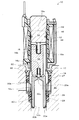
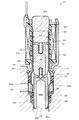
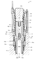
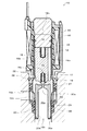
図1は、本実施の形態に係る常閉型電磁弁10の第1の閉弁状態を示す縦断面図である。図2は、本実施の形態に係る常閉型電磁弁10の第2の閉弁状態を示す縦断面図である。図3は、本実施の形態に係る常閉型電磁弁10の第1の開弁状態を示す縦断面図である。図4は、本実施の形態に係る常閉型電磁弁10の第2の開弁状態を示す縦断面図である。
FIG. 1 is a longitudinal sectional view showing a first closed state of a normally closed
本実施の形態に係る常閉型電磁弁10は、例えば、車両用アンチロックブレーキ制御装置等の液圧制御機器に組み付けられ、ブレーキの作動液の液圧制御に用いられる。
The normally closed
常閉型電磁弁10は、例えば、車両用アンチロックブレーキ制御装置等の基体30に設けられた装着孔32に例えば、Oリングからなるシール部材27、28およびストッパ部材29を介して嵌装され、環状の係止部材26により固着されて組み付けられている。基体30には、常閉型電磁弁10の嵌装方向に装着孔32を兼用する第1液路30aが設けられ、シール部材27、28の間には第2液路30bが設けられている。
The normally closed
この常閉型電磁弁10が組み付けられた車両用アンチロックブレーキ制御装置では、基体30の第1液路30a側からブレーキの作動液が流入し、開弁状態において第1液路30aと第2液路30bとが連通し、作動液が第2液路30b側へ流出する構造となっている。そして、この車両用アンチロックブレーキ制御装置においては、第1液路30aと第2液路30bとの間に介在する常閉型電磁弁10が作動液流路の一部を担っている。
In the antilock brake control device for a vehicle in which the normally closed
より具体的には、作動液は、ボディ部材12の弁座20側の流入口12bから流入して、第2開口部20bから第1開口部20aに至る連通孔20cを介して、ボディ部材12の収容空間12a内に流入し、ボディ部材12の側面に設けられた流出口12cおよびストッパ部材29の開口部を介して第2液路30b側へ流出する。そして、この常閉型電磁弁10の弁座20においては、弁体18による弁座20の第1開口部20aの開閉が行われて、作動液の液圧や流量が制御される。
More specifically, the hydraulic fluid flows in from the
次に、本実施の形態に係る常閉型電磁弁10の内部構造を具体的に説明する。
Next, the internal structure of the normally closed
常閉型電磁弁10は、円筒状の非磁性体からなるボディ部材12を有する。このボディ部材12は、一端から他端にかけて貫通した収容空間12aを有し、その一端側が閉塞されるように、例えば、溶接などにより磁性体からなる固定コア14が固着されている。ボディ部材12は、円筒状のものに限られず、後述する可動コア16と弁座20を収容するための収容空間12aを有しているものであれば貫通孔を有するハウジングであってもよい。ただし、常閉型電磁弁10の小型化の観点からは、肉薄の筒状のものが好適である。このようなボディ部材12は、例えば、絞り加工により形成することができる。
The normally closed
また、ボディ部材12の収容空間12a内には、磁性体からなる可動コア16が嵌装されている。可動コア16には、可動コア16と弁座体20との間に作動液が閉じ込められることで可動コア16の固定コア14側と弁座20側との間に生じる差圧をなくして、可動コア16を円滑に作動させるために作動液の通孔16aが設けられている。
A
また可動コア16は、固定コア14に対して縮設される第1のばね部材15を、固定コア14側の端部に有底筒状で形成された第1ばね収容部16bに収容する。可動コア16は、第1のばね部材15のばね荷重により固定コア14に対向して収容空間12a内を弁座20側に付勢されながら摺動することができる。
The
また、可動コア16は、弁座20側の端部に有底筒状に形成された第2ばね収容部16cを有する。第2ばね収容部16cには、閉弁状態において第1のばね部材15よりもばね荷重が低い第2のばね部材17が収容されている。第2のばね部材17は、球状の弁体18と当接して、弁体18を弁座20側へ付勢するためのものである。弁体18は、第2ばね収容部16cの開口部に当接保持され、かつ第2のばね部材17の圧縮伸張に伴って進退移動可能に設けられ、弁座20の第1開口部20a側の端部に当接して連通孔20cを閉塞する。このように本実施の形態では、弁体18が第2ばね収容部16cの開口部に当接保持されて、径方向の移動が規制されるため、弁座20への着座性を確実なものとすることができる。
Moreover, the
弁座20は、ボディ部材12の収容空間12a内において、固定コア14により閉塞された端部と反対側の開口端部に圧入固定されている。また弁座20は、第1開口部20aと第2開口部20bとを有し、第1開口部20aから第2開口部20bに至る連通孔20cが作動液の流動経路の一部を構成する。第1開口部20aは、弁体18により開閉される。第2開口部20bは、基体30の第1液路30a側に常時開口している。
The
また、ボディ部材12と固定コア14との外周には、コイルケース42が嵌装されている。このコイルケース42は主として磁性体から構成され、その内部にコイル46を巻装したボビン44が収納されている。コイル46に通電を行うと、固定コア14が励磁されて、固定コア14と可動コア16との間に電磁吸引力を発生する。
A
以下、本実施の形態に係る常閉型電磁弁10の動作について説明する。常閉型電磁弁10は、図1に示す第1の閉弁状態と、図2に示す第2の閉弁状態と、図3に示す第1の開弁状態と、図4に示す第2の開弁状態という動作状態をとり得る。
Hereinafter, the operation of the normally closed
図1は、常閉型電磁弁10の第1の閉弁状態を示す。第1の閉弁状態においては、コイル46が非通電状態であって、固定コア14と可動コア16との間には電磁吸引力は働いていない。このとき可動コア16は、第1のばね部材15により弁座20側に付勢され、また弁体18も第2のばね部材17により弁座20側に付勢されるとともに、可動コア16の第2ばね収容部16cの開口部に当接保持されて、弁座20の第1開口部20a側の端部に当接して連通孔20cを閉塞している。このとき弁体18は弁座20の連通孔20c側から弁内部に流入しようとする作動液の液圧反力を受けているが、本実施の形態ではコイル46への非通電状態における第1のばね部材15のばね荷重が少なくとも第2のばね部材17のばね荷重よりも大きいものとされている。これにより、閉弁状態において第2のばね部材17のばね荷重と作動液の液圧反力とによって可動コア16が固定コア14側へ押し上げられてしまうような事態が起こらず、確実に閉弁状態を維持することができる。
FIG. 1 shows a first closed state of the normally closed
次に、図2は、常閉型電磁弁10の第2の閉弁状態を示す。第2の閉弁状態においては、コイル46へ通電が行われて可動コア16が電磁吸引力により固定コア14側へ引き寄せられているが、弁体18は第2のばね部材17のばね荷重により弁座20側に押しつけられていることにより閉弁状態が保たれている。なお、この時点では第2のばね部材17のばね荷重が作動液の液圧反力よりも大きいものであるため、弁体18が弁座20から離間することはない。
Next, FIG. 2 shows a second closed state of the normally closed
次に、図3は、常閉型電磁弁10の第1の開弁状態を示す。図2に示す第2の閉弁状態からコイル46への通電量を増していくと、可動コア16に働く固定コア側への電磁吸引力が増していき、可動コア16が固定コア14側へ移動していくのに伴って第2のばね部材17も伸張していき、第2のばね部材17が弁体18を付勢するばね荷重は徐々に弱まっていく。やがて、第2のばね部材17が弁体18に与えるばね荷重が弁座20の連通孔20c側から流入する作動液が弁体18に与える液圧反力以下になったところで、図3に示すように、弁体18が徐々に弁座20から離間していき、弁座20の連通孔20cが第1開口部20a側において開放され、作動液が弁内部へと流入しはじめる。この弁体18が弁座20から離間した際においては、作動液の液圧反力が急減少するが、弁体18は、第2のばね部材17が自由長まで伸張するまでは弁座20への当接方向にばね荷重を受けているため、弁体18が弁座20から一気に離間することがない。このため本実施の形態の常閉型電磁弁10によれば、弁座20の第1開口部20aのオリフィスによる流量制限の影響を受けにくく、必要な流量を確保して細かな調圧や流量制御が可能となる。
Next, FIG. 3 shows a first valve open state of the normally closed
ここで、本実施の形態に係る常閉型電磁弁10のコイル46への通電状態においては、少なくとも可動コア16が固定コア14と当接する前に、第2のばね部材17が自由長まで伸張することが好ましい。このようにすれば、閉弁状態においては第2のばね部材17によって弁体18が閉弁方向に付勢されていても、可動コア16が固定コア14側へ移動するのに伴って第2のばね部材17が自由長になった時点で第2のばね部材17が弁体18に与える付勢荷重が消滅するため、これにより確実に開弁状態とすることができる。
Here, in the energized state of the
次に、図4は、常閉型電磁弁10の第2の開弁状態を示す。図3に示す第1の開弁状態では、第2のばね部材17のばね荷重が弁体18にかかっていたが、上述したように第2のばね部材17が可動コア16の固定コア14側への後退により自由長まで伸びきると、弁体18には弁座20の連通孔20c側から流入する作動液の液圧のみがかかることになるため、これにより弁体18は、可動コア16の移動に伴って弁座20から大きく離間して全開状態となる。
Next, FIG. 4 shows a second valve open state of the normally closed
本実施の形態では、上述したようにコイル46の非通電状態から通電状態にかけて図1から図4に示す4つの動作状態を持つことにより作動液の調圧性や流量制御性を微細なものとすることができる。 In the present embodiment, as described above, the pressure adjustment property and flow rate controllability of the hydraulic fluid are made fine by having the four operation states shown in FIGS. be able to.
以上に本発明に好適な実施の形態について説明したが、本発明は、上述した態様に限られるものではなく、発明の要旨の範囲内で種々の変形態様により実施することができる。例えば、本実施の形態に係る常閉型電磁弁10は、車両用アンチロックブレーキ制御装置に限らず、各種液圧制御機器に適用することが可能である。
Although the preferred embodiment of the present invention has been described above, the present invention is not limited to the above-described embodiment, and can be implemented by various modified embodiments within the scope of the gist of the invention. For example, the normally closed
10 常閉型電磁弁、12 ボディ部材、12a 収容空間、12b 流入口、12c 流出口、14 固定コア、15 第1のばね部材、16 可動コア、16b 第1ばね収容部、16c 第2ばね収容部、17 第2のばね部材、18 弁体、20 弁座、20a 第1開口部、20b 第2開口部、20c 連通孔
DESCRIPTION OF
Claims (4)
前記収容空間の一方の端部側を閉塞するように設けられる固定コアと、
前記収容空間の他方の端部側に固定して設けられ、作動液流路を連通させる連通孔を有する弁座と、
前記固定コアに対向して前記収容空間内を摺動可能な可動コアと、
前記可動コアを前記固定コア側から前記弁座側に付勢する第1のばね部材と、
前記弁座に当接して前記連通孔を閉塞可能な弁体と、
通電により前記固定コアを励磁して前記固定コアと前記可動コアとの間に電磁吸引力を発生させるコイルと、
を備えた常閉型電磁弁において、
前記可動コアの前記弁座側の端部に前記弁体を前記可動コア側から前記弁座側に付勢するように設けられた第2のばね部材を含み、
作動液の流入口を前記弁座の連通孔側に有し、前記コイルの通電状態において前記可動コアが前記固定コア側へ移動するのに伴って、前記第2のばね部材が前記弁体に与えるばね荷重が前記弁座の連通孔側から流入する作動液が前記弁体に与える液圧反力以下となった際に前記弁体が前記弁座から離間して開弁することを特徴とする常閉型電磁弁。 A body member having a housing space therethrough;
A fixed core provided to close one end side of the accommodation space;
A valve seat fixedly provided on the other end side of the housing space, and having a communication hole for communicating the hydraulic fluid flow path;
A movable core that is slidable in the accommodation space facing the fixed core;
A first spring member for urging the movable core from the fixed core side to the valve seat side;
A valve body capable of contacting the valve seat and closing the communication hole;
A coil for energizing the fixed core by energization to generate an electromagnetic attractive force between the fixed core and the movable core;
In the normally closed solenoid valve with
A second spring member provided at the end of the movable core on the valve seat side so as to bias the valve body from the movable core side to the valve seat side;
An inflow port for hydraulic fluid is provided on the communication hole side of the valve seat, and the second spring member is attached to the valve body as the movable core moves to the fixed core side when the coil is energized. The valve body opens away from the valve seat when the hydraulic load applied from the communication hole side of the valve seat becomes less than the hydraulic reaction force applied to the valve body. Normally closed solenoid valve.
前記コイルへの非通電状態における前記第1のばね部材のばね荷重が少なくとも前記第2のばね部材のばね荷重よりも大きいことを特徴とする常閉型電磁弁。 The normally closed solenoid valve according to claim 1,
A normally closed solenoid valve, wherein a spring load of the first spring member in a non-energized state of the coil is at least larger than a spring load of the second spring member.
前記コイルへの通電状態において、少なくとも前記可動コアが前記固定コアと当接する前に、前記第2のばね部材が自由長まで伸張することを特徴とする常閉型電磁弁。 The normally closed solenoid valve according to claim 1 or 2,
The normally closed solenoid valve, wherein the second spring member extends to a free length at least before the movable core contacts the fixed core in the energized state of the coil.
前記可動コアは、前記弁座側の端部に有底筒状に形成された前記第2のばね部材の収容部を有し、
前記弁体は、前記第2のばね部材の収容部の開口部に当接保持可能とされ、かつ前記第2のばね部材の圧縮伸張に伴って進退移動することを特徴とする常閉型電磁弁。 In the normally closed solenoid valve according to any one of claims 1 to 3,
The movable core has a housing portion for the second spring member formed in a bottomed cylindrical shape at an end on the valve seat side,
The normally closed electromagnetic wave characterized in that the valve body can be held in contact with the opening of the accommodating portion of the second spring member, and is moved forward and backward as the second spring member is compressed and expanded. valve.
Priority Applications (1)
| Application Number | Priority Date | Filing Date | Title |
|---|---|---|---|
| JP2004107069A JP2005291361A (en) | 2004-03-31 | 2004-03-31 | Normally closed solenoid valve |
Applications Claiming Priority (1)
| Application Number | Priority Date | Filing Date | Title |
|---|---|---|---|
| JP2004107069A JP2005291361A (en) | 2004-03-31 | 2004-03-31 | Normally closed solenoid valve |
Publications (1)
| Publication Number | Publication Date |
|---|---|
| JP2005291361A true JP2005291361A (en) | 2005-10-20 |
Family
ID=35324518
Family Applications (1)
| Application Number | Title | Priority Date | Filing Date |
|---|---|---|---|
| JP2004107069A Withdrawn JP2005291361A (en) | 2004-03-31 | 2004-03-31 | Normally closed solenoid valve |
Country Status (1)
| Country | Link |
|---|---|
| JP (1) | JP2005291361A (en) |
Cited By (1)
| Publication number | Priority date | Publication date | Assignee | Title |
|---|---|---|---|---|
| US9366354B2 (en) | 2012-06-12 | 2016-06-14 | Toyota Jidosha Kabushiki Kaisha | Normally closed solenoid valve |
-
2004
- 2004-03-31 JP JP2004107069A patent/JP2005291361A/en not_active Withdrawn
Cited By (1)
| Publication number | Priority date | Publication date | Assignee | Title |
|---|---|---|---|---|
| US9366354B2 (en) | 2012-06-12 | 2016-06-14 | Toyota Jidosha Kabushiki Kaisha | Normally closed solenoid valve |
Similar Documents
| Publication | Publication Date | Title |
|---|---|---|
| JP4232563B2 (en) | solenoid valve | |
| US6663194B2 (en) | Solenoid valve for brake systems | |
| JP4209281B2 (en) | Normally closed solenoid valve | |
| JP5421059B2 (en) | solenoid valve | |
| CA1040182A (en) | Electromagnetic two-way valve | |
| US20100051839A1 (en) | Magnet valve | |
| CN108027077B (en) | Damping valve and buffer | |
| JP2004504566A (en) | Proportional pressure control valve | |
| JP2010505066A (en) | Direct acting pilot pressure control solenoid | |
| JP2004360748A (en) | Normally open solenoid valve | |
| JP2005291361A (en) | Normally closed solenoid valve | |
| JP4491284B2 (en) | Hydraulic shock absorber | |
| JP2005291383A (en) | Normally closed solenoid valve | |
| JP4721819B2 (en) | Pyro-type valve | |
| JP2007051780A (en) | Relief valve | |
| JP2005282683A (en) | Normally open solenoid valve | |
| JP2005289216A (en) | Normally closed solenoid valve | |
| EP0769645A1 (en) | Proportional valve | |
| WO2011049177A1 (en) | Solenoid valve | |
| JP2005282681A (en) | Normally closed solenoid valve | |
| JP2005282747A (en) | solenoid valve | |
| JP3307696B2 (en) | Pilot operated solenoid valve | |
| JP4158038B2 (en) | solenoid valve | |
| JP4217647B2 (en) | Normally open solenoid valve | |
| JPH06700Y2 (en) | solenoid valve |
Legal Events
| Date | Code | Title | Description |
|---|---|---|---|
| RD04 | Notification of resignation of power of attorney |
Free format text: JAPANESE INTERMEDIATE CODE: A7424 Effective date: 20051213 |
|
| A300 | Withdrawal of application because of no request for examination |
Free format text: JAPANESE INTERMEDIATE CODE: A300 Effective date: 20070605 |