JP2005291318A - Coupling - Google Patents
Coupling Download PDFInfo
- Publication number
- JP2005291318A JP2005291318A JP2004105772A JP2004105772A JP2005291318A JP 2005291318 A JP2005291318 A JP 2005291318A JP 2004105772 A JP2004105772 A JP 2004105772A JP 2004105772 A JP2004105772 A JP 2004105772A JP 2005291318 A JP2005291318 A JP 2005291318A
- Authority
- JP
- Japan
- Prior art keywords
- pair
- locking
- insertion hole
- female member
- male member
- Prior art date
- Legal status (The legal status is an assumption and is not a legal conclusion. Google has not performed a legal analysis and makes no representation as to the accuracy of the status listed.)
- Pending
Links
- 230000008878 coupling Effects 0.000 title claims abstract description 8
- 238000010168 coupling process Methods 0.000 title claims abstract description 8
- 238000005859 coupling reaction Methods 0.000 title claims abstract description 8
- 230000002093 peripheral effect Effects 0.000 claims abstract description 11
- 238000003780 insertion Methods 0.000 claims description 55
- 230000037431 insertion Effects 0.000 claims description 55
- 230000000717 retained effect Effects 0.000 claims 1
- 229910052751 metal Inorganic materials 0.000 abstract description 17
- 239000002184 metal Substances 0.000 abstract description 17
- 230000004048 modification Effects 0.000 description 5
- 238000012986 modification Methods 0.000 description 5
- 238000005452 bending Methods 0.000 description 4
- 210000000078 claw Anatomy 0.000 description 3
- 238000000034 method Methods 0.000 description 3
- 210000003739 neck Anatomy 0.000 description 3
- DMFGNRRURHSENX-UHFFFAOYSA-N beryllium copper Chemical compound [Be].[Cu] DMFGNRRURHSENX-UHFFFAOYSA-N 0.000 description 1
- 230000015572 biosynthetic process Effects 0.000 description 1
- 230000001771 impaired effect Effects 0.000 description 1
- 238000009434 installation Methods 0.000 description 1
- 239000000463 material Substances 0.000 description 1
- 238000000926 separation method Methods 0.000 description 1
- 229920001187 thermosetting polymer Polymers 0.000 description 1
- 239000013585 weight reducing agent Substances 0.000 description 1
Images


Landscapes
- Snaps, Bayonet Connections, Set Pins, And Snap Rings (AREA)
- Adornments (AREA)
Abstract
Description
この発明は、ネックレス、腕環(ブレスレット)等の紐又はくさり状の装身具や、他の紐又はくさり状の部材の両端を連結するための連結具に関する。 The present invention relates to a necklace, arm ring (bracelet) or other string or wedge-shaped accessory, or a connector for connecting both ends of another string or wedge-shaped member.
一般に、ネックレスやブレスレット等の紐又はくさり状の装身具は環状にして首や腕に装着されるが、着脱の度にその両端を結び付けたりほどいたりするのはとても煩雑であるため、両端を容易に連結および離間できるようにするための種々の連結具が従来より提供されている。
そしてそれら連結具のうちで、挿入穴部を有するメス型部材と、その挿入穴部に挿脱可能な突起部を有するオス型部材との組み合わせからなるピン挿脱タイプの連結具がある。このタイプのものは連結するための操作が容易で、また連結した状態でも全体のサイズを比較的小さくすることができるという利点がある。
Generally, a necklace or bracelet string or wedge-shaped accessory is attached to the neck or arm in a ring shape. Various connectors have been provided in the past to enable connection and separation.
Among these connectors, there is a pin insertion / removal type connector composed of a combination of a female member having an insertion hole and a male member having a protrusion that can be inserted into and removed from the insertion hole. This type has the advantage that the operation for connection is easy and the overall size can be made relatively small even in the connected state.
そこで従来では、このようなピン挿脱タイプの連結具として、次のような構成のものが提案されている。
例えば、特許文献1には、オス型部材の突起部である棒体の外周に係止溝部が全周にわたって形成されており、またメス型部材である筒体にスプリングによって付勢された開閉レバーが回動可能に設けられ、棒体を筒体に挿入した際には開閉レバーの先端に形成されている係止爪部が係止溝部に嵌合して棒体と筒体を連結し、開閉レバーを付勢力に抗して回動させることによって棒体に対する嵌合を外して棒体を筒体から離脱可能にする構成の連結具が開示されている。
Therefore, conventionally, as such a pin insertion / removal type coupler, one having the following configuration has been proposed.
For example,
また、例えば、特許文献2には、オス型部材であるオス金具の胴部の外周に係合溝部が全周にわたって形成されており、またメス型部材であるメス金具が蓋体とその内側で回動可能に設けられたレバー状の底体とで構成され、蓋体の側壁部に形成した挿入部にオス金具を挿入した際に、底体の回動端部に形成した係止部が係合溝部に係合してオス金具とメス金具を連結し、底体をばねによる付勢力に抗して回動させることによってオス金具に対する係合を外して、オス金具をメス金具から離脱可能にする連結具が開示されている。
しかしながら、上記特許文献1および特許文献2に記載の従来の連結具は、共通して以下のような問題がある。例えば、どちらの連結具もレバー状の可動部を有する複雑な構成となるため、連結した状態の全体のサイズが比較的大きくなってしまうとともに故障や損傷が生じしやすく、またコスト高となってしまう問題がある。また、メス型部材には連結を外すための操作部を外部に露出させる必要があるため、装身具の一部として外観のデザイン性が損なわれるという問題もある。
However, the conventional couplers described in
この発明は、これらの問題を解決するためになされたものであり、可動部を設けない簡易な構成であって、外部に露出する操作部を設けずに容易かつ確実な連結と離脱が可能な連結具を提供することを目的とする。 The present invention has been made to solve these problems, and has a simple configuration in which no movable part is provided, and can be easily and reliably connected and detached without providing an operation part exposed to the outside. An object is to provide a connector.
この発明による連結具は、挿入穴部を備えたメス型部材と、上記挿入穴部に挿脱可能な突起部を備えたオス型部材とからなる連結具であって、上記メス型部材は、上記挿入穴部の中心軸線に対して対称な位置に互いに接近する方向に付勢された一対の係止片を備え、上記オス型部材の突起部は、上記メス型部材の挿入穴部に挿入した状態でその挿入方向の中心軸線の回りに回転可能であり、外周面における該中心軸線に対して対称な位置に上記一対の係止片と係合可能な段差又はくぼみによる一対の係止部が形成されている。
上記オス型部材の突起部は、少なくともその先端部側の所定長部分が先端方向に先細り形状で外周面の上記一対の係止部を除く部分が滑らかな面に形成されているのが望ましい。
The connector according to the present invention is a connector composed of a female member having an insertion hole and a male member having a protrusion that can be inserted into and removed from the insertion hole. A pair of locking pieces biased in directions approaching each other at positions symmetrical to the center axis of the insertion hole, and the protrusion of the male member is inserted into the insertion hole of the female member In this state, the pair of locking portions can be rotated around the central axis in the insertion direction and can be engaged with the pair of locking pieces at a position symmetrical to the central axis on the outer peripheral surface. Is formed.
It is desirable that the protrusion of the male member has at least a predetermined length portion on the tip end side tapering in the tip direction and a smooth surface on the outer peripheral surface excluding the pair of locking portions.
また、上記オス型部材の突起部の、上記メス型部材の挿入穴部に挿入する際に上記一対の係止片と接触する部分を四角柱状又は四角錐状に形成し、その外周面を構成する4面のうちの上記挿入方向の中心軸線に対して対称な一対の面にのみ上記一対の係止部を形成するとよい。
さらに、上記メス型部材の一対の係止片は、上記挿入穴部の内壁面に沿ってU字状に折り曲げた帯状の板バネの両端部を上記挿入穴部の挿入口側で抜け止め係止させ、その各自由端側を該挿入穴部の奥側へ折り返して形成するとよい。
またさらに、上記オス型部材と上記メス型部材が、一体の形状物を切断した形状の外観をなす一対の本体部を備え、その各本体部は、上記突起部が上記挿入穴部に挿入されて上記係止部と上記係止片とが係合した状態で、互いの接触面の形状が一致するようにするとよい。
Further, when the projection of the male member is inserted into the insertion hole of the female member, the portion that contacts the pair of locking pieces is formed in a quadrangular prism shape or a quadrangular pyramid shape, and the outer peripheral surface is configured. Of the four surfaces, the pair of locking portions may be formed only on a pair of surfaces that are symmetrical with respect to the central axis in the insertion direction.
Further, the pair of locking pieces of the female-type member is configured to prevent both end portions of the belt-like leaf springs bent in a U shape along the inner wall surface of the insertion hole at the insertion opening side of the insertion hole. It is good to stop and to form each free end side by folding back to the back side of the insertion hole.
Still further, the male member and the female member each have a pair of main body portions that are formed by cutting an integrally formed object, and each of the main body portions has the protruding portion inserted into the insertion hole portion. Thus, it is preferable that the shapes of the contact surfaces coincide with each other in a state where the locking portion and the locking piece are engaged.
この発明による連結具は、オス型部材の突起部をメス型部材の挿入穴部に挿入して係止部を係止片に係合させることにより、オス型部材とメス型部材とを確実に連結させることができる。その際、突起部を挿入方向の中心軸線の回りで、係止部と係止片の角度位置を一致させて挿入穴部に挿入すれば係止部と係止片を係合させることができ、あるいは係止部と係止片の角度位置がずれた状態で突起部を挿入穴部に挿入しても、オス型部材とメス型部材を上記中心軸線の回りに相対回転させることによって両者を係合させることができる。
オス型部材をメス型部材から離脱させる場合には、オス型部材とメス型部材を上記中心軸線の回りに約90°相対回転させれば、係止部と係止片の係合が外れ、容易に離脱できる。したがって可動部や外部に露出する操作部を設けずに容易かつ確実な連結と離脱が可能となる。
The connector according to the present invention reliably connects the male member and the female member by inserting the protruding portion of the male member into the insertion hole of the female member and engaging the engaging portion with the engaging piece. Can be linked. At that time, the locking portion and the locking piece can be engaged with each other by inserting the protrusion around the central axis in the insertion direction and matching the angular position of the locking portion and the locking piece into the insertion hole. Alternatively, even if the protrusion is inserted into the insertion hole with the angular position of the locking portion and the locking piece shifted, both the male member and the female member can be rotated relative to each other around the central axis. Can be engaged.
When the male member is detached from the female member, if the male member and the female member are relatively rotated about 90 ° around the central axis, the engagement between the locking portion and the locking piece is released. Easy to leave. Therefore, it is possible to easily and surely connect and disconnect without providing a movable part or an operation part exposed to the outside.
以下、この発明の好ましい実施の形態を図面を参照して具体的に説明する。
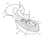
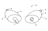
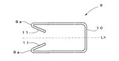
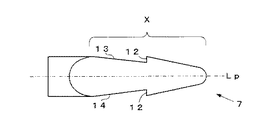
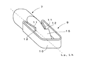
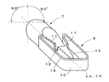
図2は、この発明による連結具の一実施形態である装身具用連結具を構成するオス型部材とメス型部材の斜視図であり、図1はそのメス型部材を水平断面にし、オス型部材の突起部がそれに挿入される前の配置で示す斜視図であり、図3はメス型部材に設けられる係止金具を図1中の矢示A方向から見た平面図、図4はオス型部材の突起部を図1中の矢示B方向から見た平面図、図5は同じくそれを図1中の矢示C方向から見た側面図である。
Preferred embodiments of the present invention will be specifically described below with reference to the drawings.
FIG. 2 is a perspective view of a male member and a female member constituting a coupling tool for jewelry that is an embodiment of the connector according to the present invention. FIG. 1 is a horizontal sectional view of the female member, and FIG. FIG. 3 is a perspective view showing the arrangement of the protrusions of FIG. 3 before being inserted therein, FIG. 3 is a plan view of the locking fitting provided on the female member, as viewed from the direction of arrow A in FIG. 1, and FIG. The top view which looked at the projection part of the member from the arrow B direction in FIG. 1, FIG. 5 is the side view which similarly saw it from the arrow C direction in FIG.
図2において、連結具1はオス型部材2とメス型部材3の2つの部材から構成されており、それらは楕円球状の形状物を長手方向に2つに切断した形状の外観をなす本体部4,5を備えている。各本体部4,5には、切断面と反対側の端部に装身具の紐又はくさり等の端部を結び付けるための連結リング6が設けられている。そしてオス型部材2は本体部4の切断面の中心位置に金属製の突起部7を設けており、メス型部材3は本体部5の切断面の中心位置に挿入穴部8が形成されている。
In FIG. 2, the
さらに、図1に示すように挿入穴部8の内部には係止金具9が設けられている。その係止金具9は、図3にも示すように、金属製の帯状の板バネを折り曲げて形成したものであり、本体部5の挿入穴部8の内壁に沿ってU字状に折り曲げられたフレーム部10と、そのフレーム部10の両端部が折曲部9aで内側へ折り曲げられ、自由端側が挿入穴部8の奥側へ折り返されて形成された一対の係止片部11とからなる。
この係止金具9を図1に示すようにメス型部材3の挿入穴部8内に装着すると、その折曲部9aが挿入穴部8の挿入口側壁面5aに当接して抜け止め係止される。そして、一対の係止片部11は、挿入穴部8の中心軸線(穴軸線Lhという)に対して対称な位置に互いに接近する方向に付勢された状態で配置され、一対の係止片として機能する。
Further, as shown in FIG. 1, a
As shown in FIG. 1, when the
一方、オス型部材2の突起部7は、図4及び図5に示すように、全体が棒状の突起部であり、その挿入方向の先端部側の所定長部分Xは先端が先細りで外周面が滑らかな面の四角錐状に形成されており、その外周面を構成する4面のうちの挿入方向の中心軸線(突起軸線Lpという)に対して対称な一対の面13,14(図4における上下の側面)にのみ一対の係止部12が形成されている。この一対の係止部12は、突起部7がメス型部材3の挿入穴部8に完全に挿入した状態で、係止金具9の一対の係止片部11と係合して抜け止めされる段差を有する形状に形成されている。他の2面15,16(図5参照)は滑らかな滑り面となっている。
On the other hand, the
また、この突起部7は、メス型部材3の挿入穴部8に挿入した状態でその突起軸線Lp(この場合は穴軸線Lhと一致する)の回りに回転可能であり、なお係止金具9と突起部7は共に熱硬化処理により強度を高くできるベリリウム銅によって形成するとよい。
また、突起部7及び係止金具9のそれぞれの本体部4,5に対する設置状態としては、後述するように突起部7が挿入穴部8に挿入されて係止部12と係止片部11とが係合した場合に、各本体部4,5の接触面の形状が一致するような角度位置で突起部7と係止金具9とを各本体部4,5に設置している。
In addition, the
In addition, as a state of installation of the
次に、以上のように構成されたこの実施形態の連結具1の連結操作について説明する。まず、この連結具1を連結させるための基本的な操作は、オス型部材2の突起部7をメス型部材3の挿入穴部8に挿入し、各係止部12を各係止片部11に係合させることによって確実に連結させることができるが、そのための具体的な操作方法としては以下に示すような2通りの方法がある。
Next, the connection operation of the
一番簡単な方法は、オス型部材2とメス型部材3の本体部4と5の接触面の楕円方向を一致させて、突起部7を挿入穴部8に矢示D方向に挿入すれば、突起軸線Lpと穴軸線Lhの回りで係止部12と係止片部11の角度位置が一致しているので、突起部7の先端部が係止金具9の一対の係止片部11をその付勢力に抗して径方向に押し分けて挿入し、係止部12を過ぎると、係止片部11がその付勢力によって突起部7の低段部に入り込み、図6に示すように係止部12を係止して突起部7の引き抜きを阻止する。したがって、オス型部材2とメス型部材3とが連結状態となる。
The simplest method is to make the elliptical directions of the contact surfaces of the
別の方法としては、オス型部材2とメス型部材3の本体部4と5の接触面の楕円方向を直交させて、突起部7を挿入穴部8に図7に示すように完全に挿入した後、オス型部材2とメス型部材3とを軸線Lp、Lhの回りに右回りでも左回りでも90度回転させることによって、係止部12と係止金具9の係止片部11とを係合させて、オス型部材2とメス型部材3とを連結させることができる。この場合には、あまり押しこむ力をかけなくても円滑に挿入することができる。そして、突起部7を突起軸線Lp回りに回転させて係止部12と係止片部11とを係合させる際には、突起部7の四角錐状の部分の外周面に係止片部11が当接しているため、90度回転したときにクリック感が得られる。
As another method, the elliptical directions of the contact surfaces of the
ここで図6に示した連結状態では、係止金具9の一対の係止片部11がそれぞれ自由端で突起部7の係止部12を係止しつつその付勢力によって突起部7を挟み込んでいるため、突起部7と係止金具9とは軸線方向に引っ張り力が作用しても外れることなく、確実に連結状態を保持する。
そして、この連結状態を解除して突起部7を係止金具9から離脱させるには、突起部7を突起軸線Lp回りに90度回転させることにより、突起部7の側面15,16が係止片部11を付勢力に抗して押し開き、係止部12が係止片部11と係合しない図7に示す状態になり、突起部7をメス型部材3の挿入穴部8から容易に引き抜くことができる。この場合にも、係止片部11の突起部7の四角錐状の外周面への当接によりクリック感が得られる。
Here, in the connected state shown in FIG. 6, the pair of locking pieces 11 of the locking
In order to release the connected state and release the protruding
また、突起部7の係止部12と係止金具9の係止片部11は、いずれも中心軸線に対称な2箇所の位置に設けているため、上記のような連結あるいは離脱のための回転操作は、左右どちらかの回転方向に90度回転させればよいことになる。
このように、この実施形態の装身具用連結具によれば、本体部内部に可動部を設けたり、レバー部のような外部に露出する操作部を設けることなく、容易かつ確実な連結と離脱が可能になる。
Moreover, since the latching | locking
As described above, according to the coupling tool for accessory of this embodiment, easy and reliable connection and disconnection can be performed without providing a movable part inside the main body part or an operation part exposed to the outside such as a lever part. It becomes possible.
さらに、この実施形態における係止金具は、1枚の板バネの両端部を折り曲げて一対の係止片部を一体的に形成しているので、部品点数が少なく組み付けが容易で耐久性が高く、軽量化及び低コスト化を効果的に図れる。
また、オス型部材とメス型部材の本体部が、それぞれ一体形状物を切断した形状のものであることにより、係止部と係止片部とを係合させた連結状態では互いの接触面の形状が一致し、連結具全体が元の一体形状物の形状そのままの外観をなし、他にレバーなどの操作部を露出させることがないため外観のデザイン性に優れた構成となっている。
Furthermore, since the locking metal fittings in this embodiment are formed by integrally bending a pair of leaf springs to form a pair of locking pieces, the number of parts is small and assembly is easy and durability is high. Thus, weight reduction and cost reduction can be effectively achieved.
In addition, since the main body part of the male member and the female member are of a shape obtained by cutting the integrally formed object, the contact surfaces of each other in the connected state in which the locking part and the locking piece part are engaged. The shape of the connector is the same, and the entire connector has the same appearance as that of the original one-piece, and the operation part such as a lever is not exposed.
また特に、この実施形態のように、オス型部材2とメス型部材3の本体部の外形を楕円球形状(直方体形状でもよい)を切断した形状のように、その切断面が真円ではなく中心軸線回りに方向性を有する形状(この実施形態の例では長径と短径で異なる半径を有する楕円形状)にすれば、その両本体部の接触面の形状を一致させるようにするだけで自然に係止部12と係止片部11の角度位置を合わせることができる。このため、例えばネックレスの両端部を自分の首の後ろ側で連結操作する場合のように、操作者の目の届かない所での手探りによる操作でも容易かつ確実に連結させることができる。
また上述した連結操作時に得られるクリック感もまた、手探りにより操作する場合には連結状態の切り替わりを知ることができるため非常に有効である。
In particular, as in this embodiment, the cut surface is not a perfect circle like the shape obtained by cutting the outer shape of the main body of the
Further, the click feeling obtained at the time of the connecting operation described above is also very effective because it is possible to know the switching of the connecting state when operating by groping.
なお、この発明による連結具において、メス型部材内に設ける係止片や、オス型部材の突起部の外周面に設ける係止部は、上述の実施形態の形状や構成に限られるものではない。少なくとも、中心軸線回りの係止片と係止部の角度を合わせてオス型部材の突起部をメス型部材の挿入穴部に挿入することによって係止片と係止部を係合させることができ、突起部を挿入穴部に挿入しきった状態で突起部をその軸線回りに回転させることにより、係止片と係止部との係合状態と非係合状態とを切り換えられる構成であればよい。 In the connector according to the present invention, the locking piece provided in the female member and the locking portion provided on the outer peripheral surface of the protrusion of the male member are not limited to the shape and configuration of the above-described embodiment. . At least the locking piece and the locking portion can be engaged by inserting the projection of the male member into the insertion hole of the female member so that the angle between the locking piece and the locking portion around the central axis is matched. It is possible to switch between the engagement state and the non-engagement state of the engagement piece and the engagement portion by rotating the projection portion around its axis while the projection portion is completely inserted into the insertion hole. That's fine.
例えば、メス型部材に設ける係止片は、図8に示す変形例のように、板バネを折り曲げて形成した係止金具19の一対の自由端部の内面に一対の係止爪21を設けたものとし、それを本体部5の段付の挿入穴部18に抜け止めさせて装着するようにしてもよい。オス型部材に設ける突起部7も、その先端側の所定長部分が四角錐状に限らず、図9に示す先端を半球状にした四角柱状、図10に示す先端を半球状にした円柱状、図11に示す円錐状などでもよい。また、その係止部12も段差によるものに限らず図9〜図11に示すような一対のくぼみ(溝)によって形成してもよい。なお、図9〜図11において、突起部及び係止部には図1〜図7と同じ符号を付している。
For example, the locking piece provided on the female member is provided with a pair of locking
また、突起部7の係止部12を形成している以外の側面を滑らかな面に形成することによって、係止片がその面に当接していても突起部を円滑に挿脱させることができる。
その他種々の変更が可能である。
なお、図1〜図7に示したこの実施形態の連結具は、ネックレス等の紐又はくさり状の装身具の両端を連結するのに適したものであり、両端の連結リング間に大きな引張り荷重を付加しないことを前提としている。しかし、突起部および係止金具などの引っ張り荷重を受ける部分の材料や形状、寸法などを任意に設計することにより、装身具以外にも電気機器などのコード類の連結部やその他日用品等への利用も可能である。
In addition, by forming the side surfaces other than the formation of the locking
Various other changes are possible.
1 to 7 is suitable for connecting both ends of a string such as a necklace or a wedge-shaped accessory, and a large tensile load is applied between the connecting rings at both ends. It is assumed that it will not be added. However, by arbitrarily designing the material, shape, dimensions, etc. of the parts that receive tensile loads such as protrusions and locking brackets, in addition to jewelry, it can be used for connecting parts of cords such as electrical equipment and other daily necessities Is also possible.
この発明は、ネックレス、腕環(ブレスレット)等の紐又はくさり状の装身具、又はペンダントなどを首にかけるための紐又はくさり状の部材の両端を連結させる連結具に好適である。その他、電気機器の給電コードや信号線コード、もしくは他日用品等における紐またはくさり状のものの両端を連結させる連結具にも利用できる。 The present invention is suitable for a string or necklace such as a necklace or an arm ring (bracelet), or a connector for connecting both ends of a string or a wedge-shaped member for hanging a pendant or the like on the neck. In addition, the present invention can also be used for a power supply cord or a signal line cord of an electric device, or a connecting tool that connects both ends of a string or a wedge-shaped object in other daily necessities.
1:連結具 2:オス型部材
3:メス型部材 4,5:本体部
6:連結リング 7:突起部
8,18:挿入穴部 9,19:係止金具
10:フレーム部 11:係止片部(係止片)
12:係止部 21:係止爪(係止片)
1: Connecting tool 2: Male member 3:
12: Locking portion 21: Locking claw (locking piece)
Claims (5)
前記メス型部材は、前記挿入穴部の中心軸線に対して対称な位置に互いに接近する方向に付勢された一対の係止片を備え、
前記オス型部材の突起部は、前記メス型部材の挿入穴部に挿入した状態でその挿入方向の中心軸線の回りに回転可能であり、外周面における該中心軸線に対して対称な位置に前記一対の係止片と係合可能な段差又はくぼみによる一対の係止部が形成されていることを特徴とする連結具。 A connector comprising a female member provided with an insertion hole and a male member provided with a projection that can be inserted into and removed from the insertion hole,
The female member includes a pair of locking pieces biased in a direction approaching each other at positions symmetrical to the center axis of the insertion hole,
The protrusion of the male member is rotatable around the central axis in the insertion direction in a state of being inserted into the insertion hole of the female member, and the protrusion on the outer peripheral surface is symmetric with respect to the central axis. A coupling tool, wherein a pair of locking portions are formed by steps or depressions engageable with the pair of locking pieces.
前記オス型部材の突起部は、少なくともその先端部側の所定長部分が先端方向に先細り形状で前記外周面の前記一対の係止部を除く部分が滑らかな面に形成されていることを特徴とする連結具。 The connector according to claim 1, wherein
The protruding portion of the male member is characterized in that at least a predetermined length portion on the tip side is tapered in the tip direction and a portion excluding the pair of locking portions on the outer peripheral surface is formed on a smooth surface. Connecting tool.
前記オス型部材の突起部の、前記メス型部材の挿入穴部に挿入する際に前記一対の係止片と接触する部分が四角柱状又は四角錐状に形成されており、その外周面を構成する4面のうちの前記挿入方向の中心軸線に対して対称な一対の面にのみ前記一対の係止部が形成されていることを特徴とする連結具。 The connector according to claim 1 or 2,
The portion of the projection of the male member that contacts the pair of locking pieces when inserted into the insertion hole of the female member is formed in a quadrangular prism shape or a quadrangular pyramid shape and constitutes the outer peripheral surface thereof The coupling tool, wherein the pair of locking portions are formed only on a pair of surfaces symmetrical with respect to the central axis in the insertion direction among the four surfaces.
前記メス型部材の一対の係止片は、前記挿入穴部の内壁面に沿ってU字状に折り曲げられた帯状の板バネの両端部が前記挿入穴部の挿入口側で抜け止め係止され、その各自由端側が該挿入穴部の奥側へ折り返されて形成されていることを特徴とする連結具。 The connector according to any one of claims 1 to 3,
The pair of locking pieces of the female-type member is provided with both ends of a belt-shaped leaf spring bent in a U shape along the inner wall surface of the insertion hole, and are retained and locked on the insertion port side of the insertion hole. And each free end side is formed by being folded back to the back side of the insertion hole.
前記オス型部材と前記メス型部材が、一体の形状物を切断した形状の外観をなす一対の本体部を備え、その各本体部は、前期突起部が前記挿入穴部に挿入されて前記係止部と前記係止片とが係合した状態で、互いの接触面の形状が一致することを特徴とする連結具。
The connector according to any one of claims 1 to 4,
The male member and the female member each have a pair of main body portions that have a shape obtained by cutting an integrally formed object, and each main body portion has a protrusion portion inserted into the insertion hole portion and the engagement member. The shape of the contact surface of each other is the same in a state where the stopper and the locking piece are engaged.
Priority Applications (1)
| Application Number | Priority Date | Filing Date | Title |
|---|---|---|---|
| JP2004105772A JP2005291318A (en) | 2004-03-31 | 2004-03-31 | Coupling |
Applications Claiming Priority (1)
| Application Number | Priority Date | Filing Date | Title |
|---|---|---|---|
| JP2004105772A JP2005291318A (en) | 2004-03-31 | 2004-03-31 | Coupling |
Publications (1)
| Publication Number | Publication Date |
|---|---|
| JP2005291318A true JP2005291318A (en) | 2005-10-20 |
Family
ID=35324483
Family Applications (1)
| Application Number | Title | Priority Date | Filing Date |
|---|---|---|---|
| JP2004105772A Pending JP2005291318A (en) | 2004-03-31 | 2004-03-31 | Coupling |
Country Status (1)
| Country | Link |
|---|---|
| JP (1) | JP2005291318A (en) |
Cited By (5)
| Publication number | Priority date | Publication date | Assignee | Title |
|---|---|---|---|---|
| JP2007307066A (en) * | 2006-05-17 | 2007-11-29 | Seberu Piko:Kk | Clasp for personal ornament |
| JP2008530479A (en) * | 2005-02-17 | 2008-08-07 | アルクティウム エーエス | Connecting device |
| WO2010148475A1 (en) * | 2009-06-24 | 2010-12-29 | Deanna Zavattin | Ornament, system including the ornament and arrangement and method |
| JP2011094736A (en) * | 2009-10-30 | 2011-05-12 | Toyoda Gosei Co Ltd | Cover |
| WO2025001149A1 (en) * | 2023-06-29 | 2025-01-02 | 致欧家居科技股份有限公司 | Female connector, male connector, connecting device, article, and article assembly |
-
2004
- 2004-03-31 JP JP2004105772A patent/JP2005291318A/en active Pending
Cited By (5)
| Publication number | Priority date | Publication date | Assignee | Title |
|---|---|---|---|---|
| JP2008530479A (en) * | 2005-02-17 | 2008-08-07 | アルクティウム エーエス | Connecting device |
| JP2007307066A (en) * | 2006-05-17 | 2007-11-29 | Seberu Piko:Kk | Clasp for personal ornament |
| WO2010148475A1 (en) * | 2009-06-24 | 2010-12-29 | Deanna Zavattin | Ornament, system including the ornament and arrangement and method |
| JP2011094736A (en) * | 2009-10-30 | 2011-05-12 | Toyoda Gosei Co Ltd | Cover |
| WO2025001149A1 (en) * | 2023-06-29 | 2025-01-02 | 致欧家居科技股份有限公司 | Female connector, male connector, connecting device, article, and article assembly |
Similar Documents
| Publication | Publication Date | Title |
|---|---|---|
| US7128595B2 (en) | Electrical connector with positive lock | |
| US5938465A (en) | Machined dual spring ring connector for coaxial cable | |
| US9666973B1 (en) | Self-locking connector coupling | |
| US7632130B2 (en) | Electrical connector and connector assembly having inner and outer plug housings | |
| EP1666783B1 (en) | Pipe joint and socket for pipe joint | |
| US20130137287A1 (en) | Electrical plug connection, in particular circular plug connector | |
| US8419462B2 (en) | Lever type connector | |
| US10263367B2 (en) | Electrical connector with rotary connector position assurance device | |
| CN101127423B (en) | Electrical connector with cam lever retainer | |
| US8591249B2 (en) | Flexible breakaway connector | |
| EP0994531A3 (en) | Connector latch | |
| JP2008288052A (en) | Lever type connector | |
| EP1130691A3 (en) | Lever-type connector | |
| US20040209503A1 (en) | Connector, set of connectors and method of connecting a connector | |
| US4530559A (en) | Locking means for a plug and receptacle connector | |
| JP2005291318A (en) | Coupling | |
| JP3917603B2 (en) | Connector | |
| EP0676830B1 (en) | Electrical connector housing assembly with improved locking means | |
| KR101417704B1 (en) | Connector joining jig and low insertion force connector | |
| JP5091983B2 (en) | Lever fitting type connector | |
| JPH0611274U (en) | Lever type connector | |
| EP1085615B1 (en) | Connector system | |
| US6227891B1 (en) | Retractable handle for power connector | |
| TWI905615B (en) | Electrical connecting device with automatic reset function during plug and unplug | |
| WO1994023473A1 (en) | Extension plug-in unit |
Legal Events
| Date | Code | Title | Description |
|---|---|---|---|
| A131 | Notification of reasons for refusal |
Effective date: 20070220 Free format text: JAPANESE INTERMEDIATE CODE: A131 |
|
| A977 | Report on retrieval |
Free format text: JAPANESE INTERMEDIATE CODE: A971007 Effective date: 20070226 |
|
| A02 | Decision of refusal |
Free format text: JAPANESE INTERMEDIATE CODE: A02 Effective date: 20070703 |