JP2005291311A - Deep sea water composite pumping pipe - Google Patents
Deep sea water composite pumping pipe Download PDFInfo
- Publication number
- JP2005291311A JP2005291311A JP2004105624A JP2004105624A JP2005291311A JP 2005291311 A JP2005291311 A JP 2005291311A JP 2004105624 A JP2004105624 A JP 2004105624A JP 2004105624 A JP2004105624 A JP 2004105624A JP 2005291311 A JP2005291311 A JP 2005291311A
- Authority
- JP
- Japan
- Prior art keywords
- pipe
- driving fluid
- inner support
- pumping
- composite
- Prior art date
- Legal status (The legal status is an assumption and is not a legal conclusion. Google has not performed a legal analysis and makes no representation as to the accuracy of the status listed.)
- Withdrawn
Links
Images
Landscapes
- Supports For Pipes And Cables (AREA)
- Rigid Pipes And Flexible Pipes (AREA)
- Quick-Acting Or Multi-Walled Pipe Joints (AREA)
Abstract
Description
本発明は、深層水複合揚水管の組立て工法に関する。詳しくは、海中に設置した流体ジェットポンプと陸上施設との接続に必要な揚水管と駆動流体送水管を一体化して迅速に施工できることを目的とし、また揚水管内に収容することで駆動流体送水管を保護することも目的の一つであり、複数に分けて作業に適した長さに製作した複合揚水管ユニットを、最後に一本の深層水複合揚水管に組立て駆動流体送水管の接続部を保護するために防護カバーを取付けて完成する深層水複合揚水管の組立て製作の技術に関するものである。 The present invention relates to a method for assembling a deep water composite pumped pipe. Specifically, the purpose is to integrate the pumping pipe and the driving fluid water pipe necessary for connection between the fluid jet pump installed in the sea and the land facility, and to construct it quickly, and the driving fluid water pipe is accommodated in the pumping pipe. One of the objectives is to protect the water, and divide the composite pumping pipe unit, which is divided into a plurality of lengths suitable for work, into a single deep water composite pumping pipe, and assemble the connecting part of the driving fluid water pipe. It is related with the technique of the assembly manufacture of the deep water compound pumped-up pipe completed by attaching a protective cover in order to protect the water.
「深層水取水管」に関して、特開2003−301484号(以下、特許文献1という)に、「すなわち、取水基地1に連結される取水管2を水中に敷設する方法であって、合成樹脂製管3を陸上において複数本接続して単位長管4とする工程、この単位長管4に所定間隔でコンクリート製のバラスト5を取り付けるとともに、水上において複数の台船6を直列に配列させて単位長管4のバラスト取り付け部分を積載し、単位長管4を水上輸送する工程、この単位長管4を水底7に敷設する工程、単位長管4の先端をアンカー8に仮固定し、次の単位長管4を敷設済みの単位長管4の先端に接続して順次水底に敷設して取水管2とする工程、を含む方法である。」の記載がある。
「深層水取水管」に関して、特開2002−147339号(以下、特許文献2という)に、「この深層水取水管30は、ポリエチレン管等からなる取水管本体32を有しており、この取水管本体32の外周には、ゴム引き布テープ等からなる座床用テープ巻き層34を設けた上で、外装線36とエア注入管38が同じ層にロングピッチでらせん巻きされている。エア注入管38の外径は外装線36の外径とほぼ同じにしてある。」の記載がある。
Regarding “deep water intake pipe”, Japanese Patent Application Laid-Open No. 2003-301484 (hereinafter referred to as Patent Document 1) states that “that is, a method of laying the
Regarding “deep water intake pipe”, Japanese Patent Application Laid-Open No. 2002-147339 (hereinafter referred to as Patent Document 2) states that “this deep
しかしながら、特許文献1には、一般規格の樹脂単管を連続接続して長尺単管を組立てて、敷設時にこれらを連結して取水管とする方法のみで、流体ジェットポンプを駆動するための駆動流体送水管を取水管または揚水管に収容固定するような技術および方法についての解決策がないなどの問題がある。
また、特許文献2には、複合管であるが対象がエアーでありエア注入管が取水管にロングピッチで螺旋巻きにされており、もし此を水の高速流体とした場合には螺旋管を旋回しながら流れることと流路長が長くなるために流体損失が大きくなり実用的でないなどの問題点がある。
However,
本発明は、深層水の取水に於いて、流体ジェットポンプを海中に設置するとき、陸上の動力用高圧ポンプから海中の流体ジェットポンプを結ぶ駆動流体送水管を揚水管に複合させることと、任意の長さに分割して組立て可能であり設置の簡便性を備え駆動流体送水管を損傷から保護することを可能とした深層水複合揚水管ユニットと、さらに該ユニットを連結接続して接続部に保護カバーを装着した深層水複合揚水管を提供することを目的とする。 In the intake of deep water, when the fluid jet pump is installed in the sea, the present invention combines a driving fluid water supply pipe connecting a land-use high-pressure pump with a fluid jet pump in the sea into a pumping pipe, and an optional A deep water composite pumped-pipe unit that can be assembled and divided into two lengths and that can protect the drive fluid water pipe from damage, and the unit is connected and connected to the connecting portion. The purpose is to provide a deep-water composite pumped pipe equipped with a protective cover.
本願発明者は、鋭意研究の結果、複合揚水管ユニットの設計製作条件を大幅に緩和し、任意の長さに分割製造でき、揚水管の管径の違いや、駆動流体送水管の管径および条数への変更にも柔軟に対応できる、組み立て式の深層水複合揚水管においてインナーサポートを考案することにより発明を完成し、上記課題を解決した。すなわち、
本発明は、所定の長さに単管を組立てて両側にホース引き出し用エクステンションパイプを取付け長尺管ユニットを製作する工程と、駆動流体送水管とインナーサポートを組付けながら長尺管ユニットに挿入する工程と、インナーサポートのC構造部切離し用コードに取ってインナーサポートを揚水管内に固定する工程と、駆動流体送水管をホース引き出し用エクステンションパイプから引出して止水処理をしてジョイントのためのカップリング取付の工程と、からなる一連の工程により組み立てた複合揚水管ユニットを連結接続し駆動流体送水管を接続して接続部に防護カバーを装着して完成する新規な深層水複合揚水管を実現したものである。
As a result of earnest research, the inventor of the present application greatly relaxed the design and manufacturing conditions of the composite pumping pipe unit and can be divided and manufactured to an arbitrary length, the difference in pipe diameter of the pumping pipe, the pipe diameter of the driving fluid feed pipe and The invention was completed by devising an inner support in an assembly-type deep water composite pumped-up pipe that can flexibly cope with changes to the number of strips, and solved the above problems. That is,
The present invention includes a step of assembling a single pipe to a predetermined length and attaching an extension pipe for hose drawing on both sides to produce a long pipe unit, and inserting the drive fluid water supply pipe and the inner support into the long pipe unit. A process for cutting the C structure part of the inner support, fixing the inner support in the pumping pipe, and pulling out the driving fluid water supply pipe from the extension pipe for pulling out the hose to stop the water. A new deep-water composite pumping pipe completed by connecting and connecting a composite pumping pipe unit assembled by a series of processes consisting of coupling and connecting a driving fluid water pipe and attaching a protective cover to the connection part It has been realized.
本発明は前記課題を解決するために次のように構成される。
本発明にいう深層水複合揚水管とは、海中の先端部分に流体ジェットポンプを装着して、深層水を揚水するときに用いる揚水管で、内部において駆動流体を送る駆動流体送水管を適切に固定してあり、敷設作業時には普通の硬質樹脂管を用いて作業するのと同様な作業性を提供するものをいう。
本発明にいうインナーサポートとは、駆動流体送水管の固定保持器具であり、揚水管内面に密着して駆動流体送水管を保持するものをいう。
本発明にいう駆動流体送水管収容溝とは、インナーサポートに設けた複数条の溝であり、保持固定する凹部をいう。
The present invention is configured as follows to solve the above-described problems.
The deep water composite pumping pipe referred to in the present invention is a pumping pipe used when pumping deep water by attaching a fluid jet pump to the tip of the sea. It is fixed and provides the same workability as working with ordinary hard resin pipes during laying work.
The inner support referred to in the present invention is a fixing / holding device for the driving fluid water pipe, and means an instrument that holds the driving fluid water pipe in close contact with the inner surface of the pumping pipe.
The driving fluid water supply pipe accommodation groove referred to in the present invention is a plurality of grooves provided in the inner support, and refers to a recess to be held and fixed.
本発明にいう嵌合連結部とは、インナーサポートの連結部であり、嵌合して接続のできる構造を持つ、延長の為の凹凸部をいう。
本発明にいうC形構造部切離し用コードとは、製造時に板バネをC形に丸めて一体成形して先端同士が突合わせされた部分を切離す為に埋め込まれたコードであり、連結器具のリングとフックが両端に各々付けられた切離し用コードのことをいう。
樹脂素材は、プラスチック、弾性体(ゴム、ウレタンラバーなど)またはこれらの複合体である。
The fitting connecting portion referred to in the present invention is a connecting portion of the inner support, and means an uneven portion for extension having a structure that can be fitted and connected.
The C-shaped structure parting cord referred to in the present invention is a cord embedded in order to separate the part where the tips are butted together by rounding the leaf spring into a C shape at the time of manufacture. This is a cutting cord with a ring and a hook attached to both ends.
The resin material is a plastic, an elastic body (rubber, urethane rubber, etc.) or a composite thereof.
本発明にいうホース引き出しエクステンションとは、長尺管の両端に取付けて長尺管の接続の為に駆動流体送水管を外部へ引出すための引出し部をもつエクステンションパイプであり、引出し部と駆動流体送水管との防水加工が容易にできる構造を持つものをいう。
本発明にいう流体ジェットポンプとは、機構部を持たない受動ポンプであり、高圧駆動流体の供給によって動作するものをいい、高圧ジェット噴流が作り出す負圧によって連行される水塊によってポンプ作用を行うものをいう。
The hose drawer extension referred to in the present invention is an extension pipe that is attached to both ends of a long pipe and has a drawer part for drawing out a driving fluid water supply pipe to connect the long pipe to the outside. It has a structure that can be easily waterproofed with the water pipe.
The fluid jet pump referred to in the present invention is a passive pump that does not have a mechanism, and operates by supplying a high-pressure driving fluid, and performs a pumping action by a water mass entrained by a negative pressure generated by the high-pressure jet jet. Say things.
本発明の深層水複合揚水管は、直列接続とする、適数本の複合揚水管ユニットと、該ユニット接続部に装着した防護カバーとを含む。
本発明の深層水複合揚水管は、複合揚水管ユニットが揚水管とするポリエチレン樹脂管適数と、両端に接続するホース引出エクステンションパイプと、適数条の駆動流体送水管と、適数のインナーサポートとを含むものから主として構成される。
The deep water composite pumped pipe of the present invention includes an appropriate number of composite pumped pipe units connected in series, and a protective cover attached to the unit connecting portion.
The deep water composite pumping pipe of the present invention includes an appropriate number of polyethylene resin pipes that the composite pumping pipe unit uses as a pumping pipe, hose extension pipes connected to both ends, an appropriate number of driving fluid water supply pipes, and an appropriate number of inner pipes. Mainly composed of support.
また、本発明の深層水複合揚水管は、インナーサポートが樹脂素材を用いる、駆動流体送水管用の必要条数の収容溝を持つC型構造体と、C型構造体の内部にモールドされた圧接用バネ板と、その両端に凹凸嵌合連結部を有し、C接合部に装着されたリングとフックの付いたC接合部切離し用コードとを含むものから主として構成される。
さらに、本発明の深層水複合揚水管は、ホース引出エクステンションパイプが駆動流体送水管を外部へ引出すための貫通孔と、クランプ金具と、貫通孔カバーとを含むものから主として構成される。
本発明の深層水複合揚水管の設置する方法は、所定の長さに単管を組立てて両側にホース引き出し用エクステンションパイプを取付け長尺管ユニットを製作する工程と、駆動流体送水管とインナーサポートを組付けながら長尺管ユニットに挿入する工程と、インナーサポートのC構造部切離し用コードに取ってインナーサポートを揚水管内に固定する工程と、駆動流体送水管をホース引き出し用エクステンションパイプから引出して止水処理をしてジョイントのためのカップリング取付の工程とからなる一連の工程により組み立てた複合揚水管ユニットを順次連結接続し、駆動流体送水管を接続し、該接続部に防護カバーを装着することにより行う。
In addition, the deep water composite pumped pipe of the present invention has a C-type structure having a required number of grooves for a driving fluid water pipe, the inner support using a resin material, and molded inside the C-type structure. It is mainly composed of a pressure contact spring plate and a concave and convex fitting connecting portion at both ends thereof, including a ring attached to the C joint portion and a C joint portion separation cord with a hook.
Furthermore, the deep water composite pumped pipe according to the present invention is mainly composed of a hose pull-out extension pipe that includes a through hole for pulling out the driving fluid water pipe to the outside, a clamp fitting, and a through hole cover.
The method of installing the deep water composite pumped pipe according to the present invention includes the steps of assembling a single pipe to a predetermined length and attaching hose extension pipes on both sides to produce a long pipe unit, a driving fluid feed pipe and an inner support Inserting into the long tube unit while assembling, taking the cord for detaching the C structure part of the inner support and fixing the inner support in the pumping pipe, and pulling out the driving fluid water supply pipe from the extension pipe for pulling out the hose Composite pumping pipe units assembled through a series of processes consisting of a water stop treatment and a coupling mounting process for joints are sequentially connected and connected, a drive fluid water pipe is connected, and a protective cover is attached to the connecting part. To do.
以上説明したように本発明により、駆動流体送水管を保護する為に揚水管の内部に駆動流体送水管インナーサポートによって一体にして複合ユニットとし、その両端に駆動流体送水管引き出しエクステンションを取付て駆動流体送水管複合揚水管ユニットとして、完成したユニットの揚水管部分を連結接続して、次に駆動流体送水管を相互に接続して、接続部の防護カバーを取り付けて揚水管路全体を組み立てることにより、要求される長さに迅速に組立ることが可能であり、施工時の作業性も向上させることができる。
また、揚水管は合成樹脂製が可撓性・防食性・施工性において適しており、特に高密度ポリエチレン管は機械的強度も高く接続作業などの施工性も良いので本発明の実施に最適であり、流体ジェットポンプの設置に本発明を適用することにより、迅速かつ適切に装着でき海洋深層水取水システムを設置する場所や条件の制約が少なくなり、施工を容易に実施することが可能となる。
As described above, according to the present invention, in order to protect the driving fluid water pipe, it is integrated with the driving fluid water pipe inner support inside the pumping pipe to form a composite unit, and the driving fluid water pipe drawing extension is attached to both ends of the combined unit. As a fluid feed pipe combined pumping pipe unit, connect the pumping pipe parts of the completed unit, then connect the driving fluid feed pipes to each other, attach the protective cover of the connecting part, and assemble the entire pumping pipe Thus, it is possible to quickly assemble to the required length, and workability during construction can also be improved.
In addition, the water pumping pipe is made of synthetic resin and is suitable for flexibility, anticorrosion, and workability. Particularly, the high-density polyethylene pipe has high mechanical strength and good workability such as connection work. Yes, by applying the present invention to the installation of a fluid jet pump, it is possible to install it quickly and appropriately, and there are less restrictions on the location and conditions for installing the deep sea water intake system, and the construction can be carried out easily. .
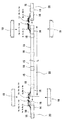
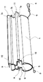
本発明の実施の形態を本発明装置に基づいて説明する。本発明の実施例の装置を図1に示す。複合揚水管ユニット20は、揚水管単管15複数本をジョイントソケット18を用いて直列接続し、その両端にホース引出しエクステンション16を接続し、その内部に駆動流体送水管を通しその両端をホース引出しエクステンション16から外部へ引出してホースカップリング・メス12a、12b、12c、12dとホースカップリング・オス13a、13b、13c、13dを装着する。該ユニットの全長については、作業を行う現場の状況や作業性を考慮し、一例として1本あたり50mから200m程度に揃えて製作する。
この複合揚水管ユニット20を複数本用意して、連結接続しホースカップリング・メス12a、12b、12c、12dとホースカップリング・オス13a、13b、13c、13dも同様に接続して、連結部は防護カバー19を用いてカバーし取付バンド(図示せず)によって固定することにより深層水複合揚水管を製作する。
An embodiment of the present invention will be described based on the apparatus of the present invention. An apparatus according to an embodiment of the present invention is shown in FIG. In the composite
A plurality of the combined
この深層水複合揚水管を用いることにより、大水深地点に流体ジェットポンプを設置するための技術的制約が大幅に緩和され、普通の大口径の合成樹脂管とほぼ変わらずに作業性もよく、物理的な強度に劣るような露出部がないので海底に設置したあと、底引き網のような漁具が通過することがあっても殆ど損傷を受けることがないことも特徴である。
また陸上の取水基地から深層水複合揚水管を流体ジェットポンプ設置水深である−30mから−100mくらいまで、次に流体ジェットポンプ装着し、そして取水管は流体ジェットポンプから取水地点まで延び、先端には大型生物の侵入を防止するカゴ付の取水口を取付けた構成の揚水ジェットポンプシステムを提供する。
By using this deep water composite pumping pipe, technical restrictions for installing a fluid jet pump at a deep water depth point are greatly relaxed, and workability is also good, almost unchanged from ordinary large diameter synthetic resin pipes, Since there is no exposed part that is inferior in physical strength, it is also characterized in that it is hardly damaged even if fishing gear such as a bottom net passes after it is installed on the seabed.
Also, from the water intake base on the ground, the deep water composite pumping pipe is installed from the fluid jet pump depth of -30m to -100m, and then the fluid jet pump is installed, and the intake pipe extends from the fluid jet pump to the intake point, and at the tip Provides a pumped-up pumping system that is equipped with a water intake with a cage that prevents the invasion of large organisms.
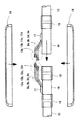
本発明の実施例の装置を図2に示す。複合揚水管ユニット20を互いに接続する部分を拡大した図であり、ホース引出しエクステンション16は予め駆動流体送水管8a、8b、8c、8dを外部に引出すための加工がなされており、ホース引出し部のカバー19が装着されるようになっている。この部分は、カバーを装着するときにシールの為のコーキング材を充填して完全な防水処理が行われる。そしてホース引出しエクステンション16同士をジョイントソケット18を介して相互に接続して駆動流体送水管8a、8b、8c、8dもホースカップリング・メス12a、12b、12c、12dホースカップリング・オス13a、13b、13c、13dも相互に接続して後に、防護カバー19を装着してハードカバーで全てを覆って駆動流体送水管が外部よりの損傷を受けにくくする。
このように、接続部分は外部からの損傷を受けにくい構造とし、長期間にわたって通常の使用では破損することがないように考慮されており、流体ジェットポンプも修理不可能であるので冗長設計を行っており、深層水揚水システムを構成するのに全体としてのバランスのとれた設計を行っている。
An apparatus according to an embodiment of the present invention is shown in FIG. It is the figure which expanded the part which connects the composite
In this way, the connection part is designed to be resistant to damage from the outside, and is considered not to be damaged under normal use over a long period of time. The fluid jet pump cannot be repaired, so a redundant design is performed. As a whole, a well-balanced design is carried out to construct a deep water pumping system.
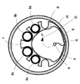
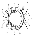
本発明の実施例の装置を図3に示す。揚水管の断面図であり、インナーサポート1が駆動流体送水管8a、8b、8c、8dを保持して管内壁に圧着している状態を示しており、深層水は流路14の部分を流れて揚水される。
高速流体のある管内にホースを裸の状態で収容すると、流れによって渦が生じたりホースに働く力で動きを生じたりすることがあり、これによって流体損失が大きくなったり、長期にわたると駆動流体送水管に損傷を生じることも考えられる。そこでインナーサポート1によりしっかりと固定することでこれらの問題を解消し、流体損失の少ない深層水複合揚水管を提供することができる。
An apparatus according to an embodiment of the present invention is shown in FIG. FIG. 5 is a cross-sectional view of a pumping pipe, showing a state in which the
If a hose is housed in a pipe with high-speed fluid in a bare state, vortices may occur due to the flow, or movement may occur due to the force acting on the hose. It is also possible to cause damage to the water pipe. Therefore, by fixing firmly with the
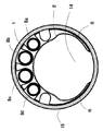
本発明の実施例の装置を図4に示す。揚水管の断面図であり、インナーサポート1が駆動流体送水管8a、8b、8c、8dを保持して深層水揚水管内に挿入された状況を示す。
切離しコード5を手前から奥方向に引くことで、接続部等を切離して揚水管路内面に固定することができる。
An apparatus according to an embodiment of the present invention is shown in FIG. It is sectional drawing of a pumping pipe, and shows the condition where the
By pulling the
本発明の実施例の装置を図5に示す。これは、インナーサポートの図であり、駆動流体送水管収容部7a、7b、7c、7d、7e、7fと連結凸部11と連結凹部10を持つものであり、切離しコード5と連結部3と5からなっている。
An apparatus according to an embodiment of the present invention is shown in FIG. This is a diagram of the inner support, which has driving fluid water
1 インナーサポート
2 スプリングプレート
3 リング
4 フック
5 コード
6 固定用ウイング
7a、7b、7c、7d、7e、7f 駆動流体送水管収容部
8a、8b、8c、8d 駆動流体送水管
9 連結バー
10 連結凹部
11 連結凸部
12、12a、12b、12c、12d ホースカップリング・メス
13、13a、13b、13c、13d ホースカップリング・オス
14 流路
15 揚水管単管
16 ホース引出しエクステンション
17 ホース引出し部カバー
18 ジョイントソケット
19 防護カバー
20 複合揚水管ユニット
30 拡がり方向
31 引抜き方向
DESCRIPTION OF
14
Claims (5)
A step of assembling a single pipe to a predetermined length, attaching a hose pull-out extension pipe on both sides to manufacture a long pipe unit, a process of inserting the drive fluid water supply pipe and the inner support into the long pipe unit, Taking the cord for separating the C structure part of the inner support and fixing the inner support in the pumping pipe, and pulling out the driving fluid water supply pipe from the extension pipe for pulling out the hose to stop the water, and installing the coupling for the joint A method of installing a new deep water composite pumped pipe in which a composite pumped pipe unit assembled by a series of processes consisting of processes is sequentially connected and connected, a driving fluid feed pipe is connected, and a protective cover is attached to the connecting part.
Priority Applications (1)
| Application Number | Priority Date | Filing Date | Title |
|---|---|---|---|
| JP2004105624A JP2005291311A (en) | 2004-03-31 | 2004-03-31 | Deep sea water composite pumping pipe |
Applications Claiming Priority (1)
| Application Number | Priority Date | Filing Date | Title |
|---|---|---|---|
| JP2004105624A JP2005291311A (en) | 2004-03-31 | 2004-03-31 | Deep sea water composite pumping pipe |
Publications (1)
| Publication Number | Publication Date |
|---|---|
| JP2005291311A true JP2005291311A (en) | 2005-10-20 |
Family
ID=35324479
Family Applications (1)
| Application Number | Title | Priority Date | Filing Date |
|---|---|---|---|
| JP2004105624A Withdrawn JP2005291311A (en) | 2004-03-31 | 2004-03-31 | Deep sea water composite pumping pipe |
Country Status (1)
| Country | Link |
|---|---|
| JP (1) | JP2005291311A (en) |
Cited By (1)
| Publication number | Priority date | Publication date | Assignee | Title |
|---|---|---|---|---|
| JP2010241161A (en) * | 2009-04-01 | 2010-10-28 | ▲海▼洋能源科技股▲分▼有限公司 | Water intake system of sea-bed cold water pipe of ocean thermal energy conversion power plant |
-
2004
- 2004-03-31 JP JP2004105624A patent/JP2005291311A/en not_active Withdrawn
Cited By (1)
| Publication number | Priority date | Publication date | Assignee | Title |
|---|---|---|---|---|
| JP2010241161A (en) * | 2009-04-01 | 2010-10-28 | ▲海▼洋能源科技股▲分▼有限公司 | Water intake system of sea-bed cold water pipe of ocean thermal energy conversion power plant |
Similar Documents
| Publication | Publication Date | Title |
|---|---|---|
| US10352110B2 (en) | Mounted downhole fiber optics accessory carrier body | |
| CN110073058A (en) | It is positioned against the ring sealing part of the wall elements of Offshore Structures | |
| US9534706B2 (en) | Subsea system for mounting a cable to a pipeline | |
| US6513597B2 (en) | Method for installing a water well pump | |
| US20240077163A1 (en) | Lined mainline service sealing and reinforcement insert and method of installation thereof | |
| EP3306169A1 (en) | Irrigation pipe connector | |
| KR200475423Y1 (en) | Cable protecting pipe | |
| US20190383425A1 (en) | Pullhead device and method of use | |
| CA2517980A1 (en) | A pipe assembly and a method for installation in a borehole | |
| JP2002369326A (en) | Pipe laying pressure feed head and pipe laying method using the same | |
| MY159512A (en) | Anchoring collar | |
| JP4750610B2 (en) | Rehabilitation of existing pipes | |
| KR200449411Y1 (en) | Jointing tube for water inside cable | |
| BRPI0902852B1 (en) | device and process for mounting a flexible duct end tip in a frame and method for mounting a flexible duct by a guide tube in a frame | |
| CN217519387U (en) | Indoor waterproof construction of water purification plant | |
| KR102541496B1 (en) | Underground buried pipe non-excavation replacement method | |
| JP5760216B2 (en) | Foundation buried drain pipe and method for adjusting the length of the foundation buried drain pipe | |
| CN216555910U (en) | Anti-drop pipe connecting structure | |
| CN1810104A (en) | Hollow rod used guide sleeve and hollow rod | |
| JP3708043B2 (en) | Sewer main repair method | |
| CN215575858U (en) | Optical cable walks line and uses fixer | |
| KR20050078400A (en) | The pipe of cable for mending and connector | |
| AU2013204202B2 (en) | Irrigation pipe connector | |
| JPH11198231A (en) | Rehabilitation method for laying optical fiber and rehabilitation construction materials | |
| KR100618111B1 (en) | Coupling Structure of Multi-Layer Resin Sewer Pipe |
Legal Events
| Date | Code | Title | Description |
|---|---|---|---|
| A300 | Withdrawal of application because of no request for examination |
Free format text: JAPANESE INTERMEDIATE CODE: A300 Effective date: 20070605 |