JP2005291288A - Controller for proportional solenoid valve - Google Patents
Controller for proportional solenoid valve Download PDFInfo
- Publication number
- JP2005291288A JP2005291288A JP2004104721A JP2004104721A JP2005291288A JP 2005291288 A JP2005291288 A JP 2005291288A JP 2004104721 A JP2004104721 A JP 2004104721A JP 2004104721 A JP2004104721 A JP 2004104721A JP 2005291288 A JP2005291288 A JP 2005291288A
- Authority
- JP
- Japan
- Prior art keywords
- valve
- signal
- proportional solenoid
- solenoid valve
- drive signal
- Prior art date
- Legal status (The legal status is an assumption and is not a legal conclusion. Google has not performed a legal analysis and makes no representation as to the accuracy of the status listed.)
- Granted
Links
- 238000006243 chemical reaction Methods 0.000 claims abstract description 10
- 239000012530 fluid Substances 0.000 claims description 14
- 238000001514 detection method Methods 0.000 claims description 3
- 230000003321 amplification Effects 0.000 abstract 3
- 238000003199 nucleic acid amplification method Methods 0.000 abstract 3
- 238000004519 manufacturing process Methods 0.000 description 11
- 238000010586 diagram Methods 0.000 description 8
- XLYOFNOQVPJJNP-UHFFFAOYSA-N water Substances O XLYOFNOQVPJJNP-UHFFFAOYSA-N 0.000 description 3
- 238000007689 inspection Methods 0.000 description 2
- 238000012423 maintenance Methods 0.000 description 2
- 230000006835 compression Effects 0.000 description 1
- 238000007906 compression Methods 0.000 description 1
- 239000007789 gas Substances 0.000 description 1
- 239000011261 inert gas Substances 0.000 description 1
- 239000007788 liquid Substances 0.000 description 1
- 238000012986 modification Methods 0.000 description 1
- 230000004048 modification Effects 0.000 description 1
- 230000007935 neutral effect Effects 0.000 description 1
- 239000003921 oil Substances 0.000 description 1
- 239000000126 substance Substances 0.000 description 1
Images
Classifications
-
- F—MECHANICAL ENGINEERING; LIGHTING; HEATING; WEAPONS; BLASTING
- F16—ENGINEERING ELEMENTS AND UNITS; GENERAL MEASURES FOR PRODUCING AND MAINTAINING EFFECTIVE FUNCTIONING OF MACHINES OR INSTALLATIONS; THERMAL INSULATION IN GENERAL
- F16K—VALVES; TAPS; COCKS; ACTUATING-FLOATS; DEVICES FOR VENTING OR AERATING
- F16K31/00—Actuating devices; Operating means; Releasing devices
- F16K31/02—Actuating devices; Operating means; Releasing devices electric; magnetic
- F16K31/06—Actuating devices; Operating means; Releasing devices electric; magnetic using a magnet, e.g. diaphragm valves, cutting off by means of a liquid
- F16K31/0644—One-way valve
- F16K31/0655—Lift valves
- F16K31/0658—Armature and valve member being one single element
-
- F—MECHANICAL ENGINEERING; LIGHTING; HEATING; WEAPONS; BLASTING
- F16—ENGINEERING ELEMENTS AND UNITS; GENERAL MEASURES FOR PRODUCING AND MAINTAINING EFFECTIVE FUNCTIONING OF MACHINES OR INSTALLATIONS; THERMAL INSULATION IN GENERAL
- F16K—VALVES; TAPS; COCKS; ACTUATING-FLOATS; DEVICES FOR VENTING OR AERATING
- F16K27/00—Construction of housing; Use of materials therefor
- F16K27/02—Construction of housing; Use of materials therefor of lift valves
- F16K27/029—Electromagnetically actuated valves
-
- F—MECHANICAL ENGINEERING; LIGHTING; HEATING; WEAPONS; BLASTING
- F16—ENGINEERING ELEMENTS AND UNITS; GENERAL MEASURES FOR PRODUCING AND MAINTAINING EFFECTIVE FUNCTIONING OF MACHINES OR INSTALLATIONS; THERMAL INSULATION IN GENERAL
- F16K—VALVES; TAPS; COCKS; ACTUATING-FLOATS; DEVICES FOR VENTING OR AERATING
- F16K31/00—Actuating devices; Operating means; Releasing devices
- F16K31/02—Actuating devices; Operating means; Releasing devices electric; magnetic
- F16K31/06—Actuating devices; Operating means; Releasing devices electric; magnetic using a magnet, e.g. diaphragm valves, cutting off by means of a liquid
- F16K31/0675—Electromagnet aspects, e.g. electric supply therefor
-
- H—ELECTRICITY
- H01—ELECTRIC ELEMENTS
- H01F—MAGNETS; INDUCTANCES; TRANSFORMERS; SELECTION OF MATERIALS FOR THEIR MAGNETIC PROPERTIES
- H01F7/00—Magnets
- H01F7/06—Electromagnets; Actuators including electromagnets
- H01F7/08—Electromagnets; Actuators including electromagnets with armatures
- H01F7/16—Rectilinearly-movable armatures
Landscapes
- Engineering & Computer Science (AREA)
- General Engineering & Computer Science (AREA)
- Mechanical Engineering (AREA)
- Physics & Mathematics (AREA)
- Electromagnetism (AREA)
- Power Engineering (AREA)
- Magnetically Actuated Valves (AREA)
Abstract
Description
本発明は比例電磁弁の制御装置に関し、特に、比例電磁弁に対して駆動信号を出力する制御装置において手動操作により比例電磁弁の制御装置の初期設定を行い得るようにした制御装置に関する。 The present invention relates to a control device for a proportional solenoid valve, and more particularly to a control device that can perform initial setting of the control device for a proportional solenoid valve by manual operation in a control device that outputs a drive signal to the proportional solenoid valve.
工業製品のような量産品を製造する製造ラインには、流体の流量や圧力を制御するために多数の比例電磁弁が使用されており、例えば特許文献1には、ダイシング装置の加工部への切削水の供給量を制御するために比例電磁弁が使用されている。比例電磁弁により制御される流体には、空気、不活性ガスおよび蒸気などの気体や、水、温水、薬液および油などの液体があり、比例電磁弁は流体流路のバルブ開度を調整する弁体と、コイルに供給される駆動信号に比例して電磁力を発生させるソレノイドとを有し、弁体にはばね部材により流体流路を閉じる方向のばね力が加えられており、ばね力に抗してソレノイドに発生する電磁力により弁体が流体流路を開くとともに電磁力の大きさに比例してバルブ開度を無段階に変化させることができる。 Many proportional solenoid valves are used in production lines for manufacturing mass-produced products such as industrial products in order to control the flow rate and pressure of fluid. Proportional solenoid valves are used to control the amount of cutting water supplied. The fluid controlled by the proportional solenoid valve includes gases such as air, inert gas and steam, and liquids such as water, hot water, chemicals and oil. The proportional solenoid valve adjusts the valve opening of the fluid flow path. A valve body and a solenoid that generates an electromagnetic force in proportion to a drive signal supplied to the coil, and a spring force is applied to the valve body in a direction to close the fluid flow path by a spring member. The valve body can open the fluid flow path by the electromagnetic force generated in the solenoid against this, and the valve opening can be changed steplessly in proportion to the magnitude of the electromagnetic force.
駆動信号を制御するためのバルブコントローラが比例電磁弁の近傍に設置されており、このバルブコントローラから比例電磁弁のコイルに供給される駆動信号が制御される。比例電磁弁が量産品を製造するための製造ラインに使用される場合には、パソコンやコンピュータなどのメインコントローラから出力されるバルブ開度に対応する指令信号に基づいて、比例電磁弁の弁体が全閉から全開までの間の任意の開度となるように、バルブコントローラから駆動信号を送るようにしており、多数の比例電磁弁が使用され製造ラインにおいては、例えば1つのメインコントローラからそれぞれの比例電磁弁のバルブコントローラに対応させて指令信号が出力され、それぞれの比例電磁弁は別々に駆動されるようになっている。 A valve controller for controlling the drive signal is installed in the vicinity of the proportional solenoid valve, and the drive signal supplied from this valve controller to the coil of the proportional solenoid valve is controlled. When the proportional solenoid valve is used in a production line for manufacturing mass-produced products, the proportional solenoid valve valve body is based on the command signal corresponding to the valve opening output from the main controller such as a personal computer or computer. A drive signal is sent from the valve controller so that the opening becomes an arbitrary opening from fully closed to fully open, and a large number of proportional solenoid valves are used. A command signal is output in correspondence with the valve controller of the proportional solenoid valve, and each proportional solenoid valve is driven separately.
メインコントローラからそれぞれのバルブコントローラに対しては、メインコントローラの特性により、例えば、4〜20mAの範囲の電流信号を指令信号として出力する場合と、0〜10Vの範囲の電圧信号を指令信号として出力する場合とがある。そのため、いずれの指令信号がバルブコントローラに入力されても、指令信号に対応したバルブ開度の駆動信号を比例電磁弁に出力するように、バルブコントローラには入力信号切換スイッチが設けられている。したがって、例えばメインコントローラからバルブ開度を全閉に設定するための指令信号として4mAの電流信号が入力された場合にはバルブ全閉に対応する駆動信号がバルブコントローラから比例電磁弁のコイルに出力され、20mAの電流信号が入力された場合にはバルブ全開に対応する駆動信号がバルブコントローラから比例電磁弁に出力される。同様に、全閉に設定するための指令信号として0Vの電圧信号が入力された場合には、バルブ全閉に対応する駆動信号がコイルに出力され、10Vの電圧信号が入力された場合にはバルブ全開に対応する駆動信号がコイルに出力されることになる。
ところで、比例電磁弁のバルブ開度はコイルに供給される駆動信号によって設定されるので、比例電磁弁により制御される流体の圧力を標準的な圧力を基準として、コントローラの製造時には4〜20mAまたは0〜10Vに対応させた標準的な駆動信号を出力するように設定されている。しかしながら、製造ラインにおいて比例電磁弁が使用される際には、比例電磁弁の入力ポートに供給される一次側圧力に応じてバルブ開度と駆動信号との関係が変化することがある。たとえば、コイルに供給される駆動信号が一定でも流体の圧力によってはバルブの開度が変化することがある。したがって、製造ラインに比例電磁弁を据え付けたり、新たな比例電磁弁に交換したり、さらには比例電磁弁の保守点検を行った後に製造ラインを立ち上げる際には、コイルに供給される駆動信号の値と実際のバルブ開度との関係を確認してバルブコントローラからコイルに出力される駆動信号の値を初期設定する必要がある。この初期設定の操作は、比例電磁弁のバルブ開度が全閉となるときと全開となるときの駆動信号を設定することにより行われており、全閉と全開の駆動信号値が設定されればその中間の値の駆動信号をメインコントローラからの指令信号の値に基づいて出力することによりバルブを任意の開度に制御することができる。 By the way, since the valve opening of the proportional solenoid valve is set by a drive signal supplied to the coil, the pressure of the fluid controlled by the proportional solenoid valve is set to 4 to 20 mA at the time of manufacture of the controller based on the standard pressure. It is set to output a standard drive signal corresponding to 0 to 10V. However, when a proportional solenoid valve is used in the production line, the relationship between the valve opening degree and the drive signal may change depending on the primary pressure supplied to the input port of the proportional solenoid valve. For example, even if the drive signal supplied to the coil is constant, the opening of the valve may change depending on the fluid pressure. Therefore, when installing a proportional solenoid valve in the production line, replacing it with a new proportional solenoid valve, or starting up the production line after maintenance and inspection of the proportional solenoid valve, the drive signal supplied to the coil It is necessary to initialize the value of the drive signal output from the valve controller to the coil by confirming the relationship between the value of and the actual valve opening. This initial setting operation is performed by setting a drive signal when the valve opening of the proportional solenoid valve is fully closed and when it is fully open, and the drive signal values for fully closed and fully open are set. For example, the valve can be controlled to an arbitrary opening degree by outputting a drive signal having an intermediate value based on the value of the command signal from the main controller.
製造ラインには上述したように多数の比例電磁弁が使用されており、1つのメインコントローラから例えば48個程度の多数の比例電磁弁に指令信号を出力してそれぞれを別々に作動させることがあり、いずれかの比例電磁弁の保守点検や交換が行われた後の初期設定操作を行うには、メインコントローラからバルブ開度を全閉に指令する信号を出力してそのときに比例電磁弁が全閉となるか否かを確認し、さらにバルブ開度を全開に指令する信号を出力してそのときに比例電磁弁が全開となるか否かを確認し、比例電磁弁が全閉となる時の駆動信号の値と全開となる時の駆動信号の値を調整している。全閉時と全開時の駆動信号が調整されれば、中間開度の駆動信号は指令信号の値に対応した中間値に設定される。 As described above, a large number of proportional solenoid valves are used in the production line, and command signals may be output from one main controller to a large number of proportional solenoid valves, for example, about 48, and each may be operated separately. In order to perform the initial setting operation after maintenance inspection or replacement of any proportional solenoid valve, the main controller outputs a signal commanding the valve opening to be fully closed, and the proportional solenoid valve is Check whether or not the valve is fully closed, and then output a signal that instructs the valve opening to be fully open, then check whether the proportional solenoid valve is fully open, and the proportional solenoid valve is fully closed. The value of the driving signal at the time and the value of the driving signal when fully opened are adjusted. If the drive signals at the time of full close and full open are adjusted, the drive signal of the intermediate opening is set to an intermediate value corresponding to the value of the command signal.
しかしながら、このような比例電磁弁の制御装置の初期設定操作は、メインコントローラから全閉時の指令信号と全開時の指令信号とを送って行う必要があるので、メインコントローラを作動させながら行う必要があり、操作性が悪いという問題点がある。 However, the initial setting operation of the control device for the proportional solenoid valve needs to be performed while the main controller is in operation because the main controller needs to send the command signal when fully closed and the command signal when fully opened. There is a problem that operability is bad.
本発明の目的は、比例電磁弁を制御するバルブコントローラの初期設定操作を容易に行い得るようにすることにある。 An object of the present invention is to facilitate an initial setting operation of a valve controller that controls a proportional solenoid valve.
本発明の比例電磁弁の制御装置は、弁体を駆動するソレノイドに指令信号に応じた駆動信号を出力して前記弁体による流体流路の開度を制御する比例電磁弁の制御装置であって、バルブ全閉に対応する前記制御信号に基づく駆動信号の全閉値を設定する全閉用の可変抵抗と、バルブ全開に対応する前記制御信号に基づく駆動信号の全開値を設定する全開用の可変抵抗とを有し、バルブ開度に対応する前記制御信号を前記駆動信号に変換して前記比例電磁弁に供給する駆動信号制御回路と、前記制御信号を前記駆動信号に変換して前記比例電磁弁に供給するオートモード位置と、前記比例電磁弁の全閉位置に対応した全閉マニュアル信号を前記駆動信号制御回路に供給する全閉マニュアル位置と、前記比例電磁弁の全開位置に対応した全開マニュアル信号を前記駆動信号制御回路に供給する全開マニュアル位置とに作動するモード切換スイッチとを有し、前記モード切換スイッチが前記全閉マニュアル位置に切り換えられた状態のもとで前記全閉用の可変抵抗によりバルブ全閉時の前記駆動信号値を補正し、前記モード切換スイッチが前記全開マニュアル位置に切り換えられた状態のもとで前記全開用の可変抵抗によりバルブ全開時の前記駆動信号値を補正することを特徴とする。 The control device for a proportional solenoid valve of the present invention is a control device for a proportional solenoid valve that outputs a drive signal corresponding to a command signal to a solenoid that drives a valve body to control the opening of a fluid flow path by the valve body. A fully-closed variable resistor for setting the fully-closed value of the drive signal based on the control signal corresponding to the valve fully closed, and a fully-open value for setting the fully-open value of the drive signal based on the control signal corresponding to the valve fully open A drive signal control circuit that converts the control signal corresponding to a valve opening to the drive signal and supplies the drive signal to the proportional solenoid valve; and converts the control signal to the drive signal and Corresponding to the auto mode position supplied to the proportional solenoid valve, the fully closed manual position supplying the drive signal control circuit with the fully closed manual signal corresponding to the fully closed position of the proportional solenoid valve, and the fully open position of the proportional solenoid valve Fully open manifold A mode changeover switch that operates to a fully open manual position for supplying an AL signal to the drive signal control circuit, and the full changeover switch is operated under the state where the mode changeover switch is switched to the fully closed manual position. The drive signal value when the valve is fully closed is corrected by a variable resistor, and the drive signal value when the valve is fully opened by the fully open variable resistor under the state where the mode switch is switched to the fully open manual position. It is characterized by correcting.
本発明の比例電磁弁の制御装置は、外部からの指令信号に基づいて当該指令信号のレベルを変換して制御信号を生成するレベル変換部を有することを特徴とする。また、本発明の比例電磁弁の制御装置は、外部からの指令信号が電流信号である場合と電圧信号である場合とのいずれの場合においても、バルブ開度に対応した共通信号に変換して前記レベル変換部に共通信号を出力する入力切換部を有することを特徴とする。さらに、本発明の比例電磁弁の制御装置は、前記比例電磁弁に供給される駆動信号を、前記比例電磁弁からのソレノイド電流検出値に基づいてフィードバック制御する演算部を有することを特徴とする。 The proportional solenoid valve control device according to the present invention includes a level conversion unit that converts a level of the command signal based on a command signal from the outside to generate a control signal. Further, the proportional solenoid valve control device of the present invention converts the command signal from the outside into a common signal corresponding to the valve opening in both cases where the signal is a current signal and a voltage signal. The level conversion unit includes an input switching unit that outputs a common signal. Furthermore, the control device for a proportional solenoid valve according to the present invention includes a calculation unit that feedback-controls a drive signal supplied to the proportional solenoid valve based on a solenoid current detection value from the proportional solenoid valve. .
本発明によれば、比例電磁弁に駆動信号を出力する駆動信号出力回路に設けられたモード切換スイッチを全閉マニュアル位置に切り換えた状態のもとで全閉用の可変抵抗によりバルブ開度を全閉状態に設定するための制御信号を補正することができ、モード切換スイッチを全開マニュアル位置に切り換えた状態のもとで全開用の可変抵抗によりバルブ開度を全開状態に設定するための制御信号を補正することができる。これにより、メインコントローラから指令信号を出力することなく、比例電磁弁を全閉位置に設定するための制御信号と全開位置に設定するための制御信号とを制御装置に初期設定することができる。 According to the present invention, the valve opening is set by the fully-closed variable resistor under the state where the mode selector switch provided in the drive signal output circuit that outputs the drive signal to the proportional solenoid valve is switched to the fully-closed manual position. The control signal for setting the fully closed state can be corrected, and the control for setting the valve opening to the fully open state by the fully open variable resistor when the mode selector switch is switched to the fully open manual position. The signal can be corrected. Thereby, without outputting a command signal from the main controller, a control signal for setting the proportional solenoid valve to the fully closed position and a control signal for setting to the fully open position can be initialized in the control device.
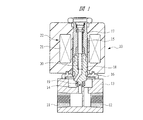
以下、本発明の実施の形態を図面に基づいて詳細に説明する。図1は比例電磁弁の一例を示す一部切り欠き正面図であり、この比例電磁弁10は一次側ポート11と二次側ポート12とが形成されたジョイントブロック13を有し、ジョイントブロック13には一次側ポート11と二次側ポート12とを連通させる連通穴14が形成されている。ジョイントブロック13には連通穴14を閉塞するようにアーマチュアガイドチューブ15が固定フランジ16により取り付けられており、ガイドチューブ15内にはストッパ17が固定されるとともに、プランジャ18が軸方向に移動自在に組み込まれている。プランジャ18の先端にはジョイントブロック13に設けられた弁座に接触して連通穴14を開閉するゴム製の弁体19が取り付けられ、弁体19の弁座に対する閉塞力を加えるために、プランジャ18内には圧縮コイルばね20が組み込まれている。ガイドチューブ15の外側にはコイル21が巻き付けられたソレノイド22が取り付けられており、コイル21に駆動信号を供給すると、ばね力に抗してプランジャ18が弁座から離れる方向に移動して弁体19は弁座からはなれて一次側ポート11と二次側ポート12とが連通穴14を介して連通状態となる。
Hereinafter, embodiments of the present invention will be described in detail with reference to the drawings. FIG. 1 is a partially cutaway front view showing an example of a proportional solenoid valve. This
図1は弁体19が弁座に接触して連通穴14が閉じられた状態つまりバルブ全閉の状態を示しており、コイル21に対する駆動信号の値により、弁体19はバルブ全閉状態と全開状態とこれらの間の任意の中間開度の位置に作動する。したがって、この比例電磁弁10が流体の流量を制御するために使用されると、一次側ポート11から二次側ポート12に向けて流れる流体の流量がバルブ開度に応じて制御され、流体の圧力を制御するために使用されると二次側ポート12に向けて吐出する流体の圧力がバルブ開度に応じて制御される。
FIG. 1 shows a state in which the
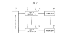
図2は工業製品の製造ラインに使用されている比例電磁弁10の制御回路を示すブロック図であり、多数の比例電磁弁10のそれぞれにはバルブコントローラ31から駆動信号がコイル21に供給されるようになっており、それぞれのバルブコントローラ31にはメインコントローラ32から指令信号が送られるようになっている。メインコントローラ32からはそれぞれの比例電磁弁10に対してバルブ全閉、バルブ全開およびバルブ中間開度の位置に対応する指令信号が出力され、この指令信号としては、メインコントローラ32の種類によって、4〜20mAの電流信号の場合と、0〜10Vの電圧信号の場合とがある。
FIG. 2 is a block diagram showing a control circuit of the
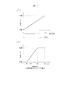
図3(A)は指令信号とバルブ開度との関係を示すバルブ特性線図であり、メインコントローラ32が電流信号を指令信号として出力する場合には、バルブを全閉させるときには4mAが指令信号として出力され、全開させるときには20mAが出力され、これらの間の任意の電流信号が出力されるとバルブは指令信号に対応した任意の開度となる。また、メインコントローラ32が電圧信号を指令信号として出力する場合には、バルブを全閉させるときには0Vが指令信号として出力され、全開させるときには10Vが出力され、これらの間の任意の電圧信号が出力されるとバルブは指令信号に対応した任意の開度となる。
FIG. 3A is a valve characteristic diagram showing the relationship between the command signal and the valve opening. When the
図3(B)は、比例電磁弁10に供給される駆動信号とバルブ開度の一例を示す特性線図であり、比例電磁弁10のバルブ開度は、比例電磁弁10のサイズなどによって相違するが、たとえば、図3(B)に示すように、比例電磁弁10のコイル21に50mA以下の駆動信号が供給されると、バルブ開度は全閉になりこれを超える駆動信号が供給されるとバルブ開度は全閉状態から開き始め、200mAの駆動信号が供給されると全開状態となる。
FIG. 3B is a characteristic diagram showing an example of the drive signal supplied to the
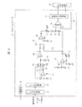
図4は図2に示されたバルブコントローラ31の内部構造を示す制御回路図であり、バルブコントローラ31は外部の電源ユニットから電源部30に供給される電力により作動するようになっている。バルブコントローラ31には、前述のように、メインコントローラ32から指令信号として電圧信号が送られてくる場合と電流信号が送られてくる場合とがあり、入力信号の種類に応じて図2に示すようにバルブコントローラ31に設けられた入力切換スイッチ33が作業者により操作される。バルブコントローラ31内には、入力切換スイッチ33の操作により作動する入力切換部34が組み込まれており、指令信号として電圧信号が入力されても電流信号が入力されても、この入力切換部34によりそれぞれバルブ開度に対応した電圧値の準正規化信号が生成される。
FIG. 4 is a control circuit diagram showing the internal structure of the
準正規化信号はレベル変換部35に送られて、準正規化信号がバルブ開度に対応した制御信号に変換される。レベル変換部35は指令信号がバルブ全閉の信号であるときには制御信号として0Vの制御信号を出力し、指令信号がバルブ全開の信号であるときには制御信号として例えば1Vの制御信号を出力し、全閉と全開の間の任意の開度の信号であるときにはバルブ開度に対応した制御信号を出力する。 The quasi-normalized signal is sent to the level converting unit 35, and the quasi-normalized signal is converted into a control signal corresponding to the valve opening. The level conversion unit 35 outputs a control signal of 0V as a control signal when the command signal is a valve fully closed signal, and outputs a control signal of, for example, 1V as a control signal when the command signal is a valve fully open signal. When it is a signal of an arbitrary opening between closed and fully open, a control signal corresponding to the valve opening is output.
バルブコントローラ31はレベル変換部35からの制御信号の値に応じて比例電磁弁10のコイル21にバルブ開度に対応した駆動信号を供給するための駆動信号制御回路36を有している。この駆動信号制御回路36の接続部37は演算部38を介して駆動信号増幅部39に接続されており、比例電磁弁のコイル21には指令信号のバルブ開度に対応した駆動信号が出力される。コイル21に流れる電流は温度によって変化するので温度変化を補償するため、比例電磁弁10からはソレノイド電流検出値のフィードバック信号が信号線40により演算部38に送られ、駆動信号はフィードバック制御される。
The
駆動信号制御回路36は、接続部37を介して直列に接続された2つの固定抵抗41,42と、バルブ全開時の駆動信号値を補正する全開設定用の可変抵抗43とバッファ44とを有する回路45を有しており、回路45にはバッファ46を介してレベル変換部35に接続されるとともに、バルブ全閉時の駆動信号値を補正する全閉設定用の可変抵抗47を有するオペアンプ48が接続されている。したがって、レベル変換部35からバルブ開度に対応した制御信号が出力されると、制御信号は固定抵抗41,42を含めて可変抵抗43,47によりバルブ開度に対応する駆動信号に変換されて演算部38に出力される。
The drive
バルブコントローラ31には、レベル変換部35から出力される全閉のバルブ開度の制御信号に対応した全閉マニュアル信号を駆動信号制御回路36に供給する0V電位が全閉マニュアル信号入力部51として設けられて駆動信号制御回路36に接続されている。また、バルブコントローラ31には、レベル変換部35から出力される全開のバルブ開度の制御信号に対応した全開マニュアル信号を駆動信号制御回路36に供給する全開マニュアル信号入力部52が設けられている。
In the
バルブコントローラ31にはモード切換スイッチ53が設けられ、このモード切換スイッチ53は作業者によりオートモード位置53aと、全開マニュアル位置53bと、これらの2位置以外の中立位置である全閉マニュアル位置53cとの3位置に操作される。オートモード位置53aに操作されると、レベル変換部35は駆動信号制御回路36に接続され、制御信号は駆動信号に変換されて比例電磁弁10にはメインコントローラ32からの指令信号のバルブ開度に対応した駆動信号が送られる。
The
モード切換スイッチ53が全閉マニュアル位置53cに操作されると、駆動信号制御回路36の入力部は全閉マニュアル信号入力部51の0Vが入力され、駆動信号制御回路36にはバルブ開度全閉が指令されたときにレベル変換部35から出力される制御信号と同一値の全閉マニュアル信号が入力される。一方、モード切換スイッチ53が全開マニュアル位置53bに操作されると、駆動信号制御回路36の入力部は全開マニュアル信号入力部52に接続され、駆動信号制御回路36にはバルブ開度全開が指令されたときにレベル変換部35から出力される制御信号と同一値の全開マニュアル信号が入力される。
When the
比例電磁弁10に対してバルブコントローラ31を初期設定するには、モード切換スイッチ53を全閉マニュアル位置53cに切り換えた状態のもとで可変抵抗47を調整し、次に、モード切換スイッチ53を全開マニュアル位置53bに切り換えた状態のもとで可変抵抗43を調整する。これにより、バルブ全閉と全開に対応する指令信号がメインコントローラ32から送られてきたときにおける駆動信号のバルブ全閉時と全開時との接続部37の分圧が変化し、演算部38を介して駆動信号増幅部39に供給される駆動信号の電流値が補正される。
In order to initially set the
したがって、例えば、コイル21に50mAの駆動信号が供給されるとバルブが全閉状態から開き始め、200mAの駆動信号が供給されるとバルブが全開状態になるという特性に予め設定されていた比例電磁弁10を実際に製造ラインで使用する場合には、一次側ポート11に供給される流体の圧力などによってバルブが全閉状態から開き始めるとき、およびバルブが全開状態となるときの駆動信号の値が設定値と相違することになることがある。その場合には、可変抵抗43,47をマニュアル操作してバルブ全閉とバルブ全開の指令信号によって比例電磁弁10が全閉位置と全開位置とに作動するように、比例電磁弁10をバルブ全閉状態と全開状態とに設定するための駆動信号の値を補正する。これらの駆動信号の値が補正されれば、バルブ中間開度に対応する指令信号に対しては、指令信号に対応した駆動信号がコイル21に供給されてバルブ開度が指令値に対応した開度に設定される。
Therefore, for example, the proportional electromagnetic that has been set in advance has a characteristic that the valve starts to open from a fully closed state when a 50 mA drive signal is supplied to the
このように、バルブコントローラ31には全閉マニュアル信号入力部51と全開マニュアル信号入力部52とが組み込まれ、モード切換スイッチ53によりバルブコントローラ31をオートモードとマニュアルモードとに切り換えることができるので、メインコントローラ32から初期設定用として全閉用の指令信号と全開用の指令信号とを出力することなく、バルブコントローラ31の作動特性を初期設定することができる。初期設定する場合には、モード切換スイッチ53を全閉マニュアル位置53cに切り換えると、メインコントローラ32から指令信号が出力されているときであっても出力されていないときであっても、メインコントローラ32から全閉用の指令信号が出力されたときと同じ値の全閉マニュアル信号が全閉マニュアル信号入力部51から駆動信号制御回路36に送られる。一方、モード切換スイッチ53を全開マニュアル位置53bに切り換えると、メインコントローラ32から全開用の指令信号が出力されたときと同じ値の全開マニュアル信号が全開マニュアル信号入力部52から駆動信号制御回路36に送られるので、メインコントローラ32から独立させて比例電磁弁10に対応するバルブコントローラ31を初期設定することができる。これにより、メインコントローラ32から指令信号をバルブコントローラ31に入力させなくとも、比例電磁弁に合わせてバルブコントローラ31の初期設定操作を容易に行うことができる。
As described above, the
本発明は前記実施の形態に限定されるものではなく、その要旨を逸脱しない範囲で種々変更可能である。比例電磁弁10としては、図1に示すタイプに限定されることなく、コイル21に供給される駆動信号によりバルブ開度を任意の開度に変化させることができるものであれば、図示するものに限定されることない。また、標準的な駆動信号としては、上述した50〜200mAに限定されることなく、制御される流体の流量や圧力に応じて任意の駆動信号により作動する比例電磁弁を制御することができる。
The present invention is not limited to the above-described embodiment, and various modifications can be made without departing from the scope of the invention. The
10 比例電磁弁
11 一次側ポート
12 二次側ポート
13 ジョイントブロック
14 連通穴
21 コイル
31 バルブコントローラ
32 メインコントローラ
33 入力切換スイッチ
34 入力切換部
35 レベル変換部
36 駆動信号制御回路
37 接続部
38 演算部
39 駆動信号増幅部
43 可変抵抗(全開用の可変抵抗)
47 可変抵抗(全閉用の可変抵抗)
51 全閉マニュアル信号入力部
52 全開マニュアル信号入力部
53 モード切換スイッチ
53a オートモード位置
53b 全開マニュアル位置
53c 全閉マニュアル位置
DESCRIPTION OF
47 Variable resistance (variable resistance for full closure)
51 Fully closed manual signal input unit 52 Fully open manual
Claims (4)
バルブ全閉に対応する前記制御信号に基づく駆動信号の全閉値を設定する全閉用の可変抵抗と、バルブ全開に対応する前記制御信号に基づく駆動信号の全開値を設定する全開用の可変抵抗とを有し、バルブ開度に対応する前記制御信号を前記駆動信号に変換して前記比例電磁弁に供給する駆動信号制御回路と、
前記制御信号を前記駆動信号に変換して前記比例電磁弁に供給するオートモード位置と、前記比例電磁弁の全閉位置に対応した全閉マニュアル信号を前記駆動信号制御回路に供給する全閉マニュアル位置と、前記比例電磁弁の全開位置に対応した全開マニュアル信号を前記駆動信号制御回路に供給する全開マニュアル位置とに作動するモード切換スイッチとを有し、
前記モード切換スイッチが前記全閉マニュアル位置に切り換えられた状態のもとで前記全閉用の可変抵抗によりバルブ全閉時の駆動信号値を補正し、前記モード切換スイッチが前記全開マニュアル位置に切り換えられた状態のもとで前記全開用の可変抵抗によりバルブ全開時の前記駆動信号値を補正することを特徴とする比例電磁弁の制御装置。 A control device for a proportional electromagnetic valve that outputs a drive signal corresponding to a command signal to a solenoid that drives a valve body to control an opening of a fluid flow path by the valve body,
Fully closed variable resistor for setting the fully closed value of the drive signal based on the control signal corresponding to the valve fully closed, and fully open variable for setting the fully open value of the drive signal based on the control signal corresponding to the valve fully open A drive signal control circuit that has a resistance and converts the control signal corresponding to a valve opening to the drive signal and supplies the drive signal to the proportional solenoid valve;
An auto mode position that converts the control signal into the drive signal and supplies it to the proportional solenoid valve, and a fully closed manual signal that supplies a fully closed manual signal corresponding to the fully closed position of the proportional solenoid valve to the drive signal control circuit A mode changeover switch that operates to a position and a fully open manual position that supplies a fully open manual signal corresponding to the fully open position of the proportional solenoid valve to the drive signal control circuit;
Under the state where the mode switch is switched to the fully closed manual position, the drive signal value when the valve is fully closed is corrected by the fully closed variable resistor, and the mode switch is switched to the fully opened manual position. A control device for a proportional solenoid valve, wherein the drive signal value when the valve is fully opened is corrected by the fully open variable resistor under the state of being applied.
Priority Applications (7)
| Application Number | Priority Date | Filing Date | Title |
|---|---|---|---|
| JP2004104721A JP3814277B2 (en) | 2004-03-31 | 2004-03-31 | Control device for proportional solenoid valve |
| US11/547,148 US7389968B2 (en) | 2004-03-31 | 2005-03-03 | Proportional solenoid valve control device |
| CNB2005800102894A CN100432511C (en) | 2004-03-31 | 2005-03-03 | Proportional solenoid valve control device |
| EP05719943.2A EP1734296B1 (en) | 2004-03-31 | 2005-03-03 | Controller of proportional solenoid valve |
| KR1020067022313A KR100824864B1 (en) | 2004-03-31 | 2005-03-03 | Proportional solenoid valve control device |
| PCT/JP2005/003639 WO2005098295A1 (en) | 2004-03-31 | 2005-03-03 | Controller of proportional solenoid valve |
| TW094107442A TWI299385B (en) | 2004-03-31 | 2005-03-11 | Control device for proportional solenoid valve |
Applications Claiming Priority (1)
| Application Number | Priority Date | Filing Date | Title |
|---|---|---|---|
| JP2004104721A JP3814277B2 (en) | 2004-03-31 | 2004-03-31 | Control device for proportional solenoid valve |
Publications (2)
| Publication Number | Publication Date |
|---|---|
| JP2005291288A true JP2005291288A (en) | 2005-10-20 |
| JP3814277B2 JP3814277B2 (en) | 2006-08-23 |
Family
ID=35125153
Family Applications (1)
| Application Number | Title | Priority Date | Filing Date |
|---|---|---|---|
| JP2004104721A Expired - Fee Related JP3814277B2 (en) | 2004-03-31 | 2004-03-31 | Control device for proportional solenoid valve |
Country Status (7)
| Country | Link |
|---|---|
| US (1) | US7389968B2 (en) |
| EP (1) | EP1734296B1 (en) |
| JP (1) | JP3814277B2 (en) |
| KR (1) | KR100824864B1 (en) |
| CN (1) | CN100432511C (en) |
| TW (1) | TWI299385B (en) |
| WO (1) | WO2005098295A1 (en) |
Cited By (1)
| Publication number | Priority date | Publication date | Assignee | Title |
|---|---|---|---|---|
| JP2024010427A (en) * | 2022-07-12 | 2024-01-24 | Ckd株式会社 | Proportional valve control device and proportional valve control method |
Families Citing this family (15)
| Publication number | Priority date | Publication date | Assignee | Title |
|---|---|---|---|---|
| EP2345355B1 (en) * | 2006-12-06 | 2013-04-24 | RHEAVENDORS SERVICES S.p.A. | Beverage preparing and dispensing machine and method |
| US8378249B2 (en) * | 2008-05-29 | 2013-02-19 | Illinois Tool Works Inc. | Method and apparatus for proportional valve actuation in a plasma cutter |
| KR101859631B1 (en) | 2010-05-11 | 2018-06-27 | 파커-한니핀 코포레이션 | Pressure compensated hydraulic system having differential pressure control |
| CN102170287B (en) * | 2010-12-23 | 2014-03-12 | 西安航空动力控制科技有限公司 | Control method for position servo system based on high-speed switch valve |
| NL2007191C2 (en) * | 2011-03-25 | 2012-09-26 | Daf Trucks Nv | Suspension system for a driver's compartment of a vehicle. |
| EP2584570A1 (en) * | 2011-10-21 | 2013-04-24 | Metso Paper Inc. | Booster for a digital hydraulic controller and method for using a booster in connection with a digital hydraulic controller |
| US9360870B2 (en) | 2012-07-18 | 2016-06-07 | Lynch Fluid Controls Inc. | Digital proportional wireless control |
| JP5641447B2 (en) * | 2012-08-20 | 2014-12-17 | Smc株式会社 | Solenoid valve control device |
| NL2009504C2 (en) * | 2012-09-24 | 2014-03-25 | Daf Trucks Nv | Suspension system for a driver's compartment of a vehicle. |
| CN106932666A (en) * | 2015-12-31 | 2017-07-07 | 沪东重机有限公司 | Multiple-way valve control function method of testing |
| JP2018072291A (en) * | 2016-11-04 | 2018-05-10 | 株式会社デンソーウェーブ | Water leakage detection system |
| JP7084240B2 (en) * | 2018-07-27 | 2022-06-14 | アズビル株式会社 | Positioner operation mode determination device and method |
| CN113007181A (en) * | 2019-12-20 | 2021-06-22 | 中国科学院沈阳自动化研究所 | Underwater hydraulic system control and data acquisition device |
| CN111726721B (en) * | 2020-06-17 | 2023-07-07 | 佛山博易听集成科技有限公司 | Adjustable over-ear sound isolation |
| CN119001280B (en) * | 2024-08-09 | 2026-01-20 | 中国船舶集团有限公司第七〇八研究所 | An electro-hydraulic control proportional valve amplifier condition monitoring test bench and its monitoring method |
Citations (7)
| Publication number | Priority date | Publication date | Assignee | Title |
|---|---|---|---|---|
| JPH07243640A (en) * | 1994-03-08 | 1995-09-19 | Toto Ltd | Combustion controller |
| JPH07310918A (en) * | 1994-05-17 | 1995-11-28 | Gastar Corp | Combustion appliance with proportional valve and its proportional valve adjusting device |
| JPH08303629A (en) * | 1995-04-27 | 1996-11-22 | Samsung Electronics Co Ltd | Proportional solenoid valve control system |
| JP2000081914A (en) * | 1998-06-30 | 2000-03-21 | Yamatake Corp | Flow control device |
| JP2001159333A (en) * | 1999-12-03 | 2001-06-12 | Nissan Motor Co Ltd | Electromagnetic valve device for internal combustion engine |
| JP2002313753A (en) * | 2001-04-19 | 2002-10-25 | Tokyo Seimitsu Co Ltd | Cutting water supply controller for dicing device |
| JP2004138178A (en) * | 2002-10-18 | 2004-05-13 | Ckd Corp | Fluid supply control device |
Family Cites Families (18)
| Publication number | Priority date | Publication date | Assignee | Title |
|---|---|---|---|---|
| DE1295896B (en) * | 1962-09-29 | 1969-05-22 | Weisheit Georg | Control device for the regulation of flowing media |
| US3469590A (en) * | 1966-10-17 | 1969-09-30 | Monsanto Co | Modulating control valve |
| US3517680A (en) * | 1968-03-14 | 1970-06-30 | Foxboro Co | Control apparatus and method for processes having long time lags |
| US3946284A (en) * | 1974-08-19 | 1976-03-23 | Rexnord, Inc. | Circuit for controlling damp shock loading |
| US3949278A (en) * | 1974-12-31 | 1976-04-06 | International Business Machines Corporation | Document transfer device drive |
| US4017056A (en) * | 1976-02-23 | 1977-04-12 | Westinghouse Electric Corporation | Servo control system for electro-hydraulic inlet valves |
| KR890008499A (en) * | 1987-11-20 | 1989-07-10 | 고가 요시네 | Solenoid valve drive control circuit |
| US4967781A (en) * | 1989-04-05 | 1990-11-06 | Borg-Warner Automotive Electronic & Mechanical Systems Corporation | Proportional solenoid valve |
| DE3911259C2 (en) * | 1989-04-07 | 1994-03-17 | Rexroth Mannesmann Gmbh | Control electronics for an electrically adjustable control valve |
| DE4201652C2 (en) * | 1992-01-22 | 1997-11-06 | Rexroth Mannesmann Gmbh | Proportional valve with control circuit and mains voltage operation |
| KR950013136B1 (en) * | 1993-04-16 | 1995-10-25 | 삼성중공업주식회사 | Amplifier for electromagnetic proportional valve |
| KR100279416B1 (en) * | 1996-12-31 | 2001-02-01 | 정몽규 | Proportional control valve drive |
| US5787915A (en) * | 1997-01-21 | 1998-08-04 | J. Otto Byers & Associates | Servo positioning system |
| JP3349958B2 (en) * | 1998-06-25 | 2002-11-25 | サーパス工業株式会社 | Coupling device for liquid transfer |
| US6364281B1 (en) * | 2000-03-22 | 2002-04-02 | Eaton Corporation | Method of energizing solenoid operated valves |
| US6850402B2 (en) * | 2002-03-01 | 2005-02-01 | Honeywell International Inc. | Circuit and method for controlling current flow through a solenoid |
| JP3706601B2 (en) * | 2002-07-30 | 2005-10-12 | 三菱重工業株式会社 | Flow control device |
| US7076997B2 (en) * | 2004-05-12 | 2006-07-18 | Honda Motor Co., Ltd. | Apparatus for testing automatic transmission solenoid valves |
-
2004
- 2004-03-31 JP JP2004104721A patent/JP3814277B2/en not_active Expired - Fee Related
-
2005
- 2005-03-03 WO PCT/JP2005/003639 patent/WO2005098295A1/en not_active Ceased
- 2005-03-03 CN CNB2005800102894A patent/CN100432511C/en not_active Expired - Fee Related
- 2005-03-03 US US11/547,148 patent/US7389968B2/en not_active Expired - Fee Related
- 2005-03-03 KR KR1020067022313A patent/KR100824864B1/en not_active Expired - Fee Related
- 2005-03-03 EP EP05719943.2A patent/EP1734296B1/en not_active Ceased
- 2005-03-11 TW TW094107442A patent/TWI299385B/en not_active IP Right Cessation
Patent Citations (7)
| Publication number | Priority date | Publication date | Assignee | Title |
|---|---|---|---|---|
| JPH07243640A (en) * | 1994-03-08 | 1995-09-19 | Toto Ltd | Combustion controller |
| JPH07310918A (en) * | 1994-05-17 | 1995-11-28 | Gastar Corp | Combustion appliance with proportional valve and its proportional valve adjusting device |
| JPH08303629A (en) * | 1995-04-27 | 1996-11-22 | Samsung Electronics Co Ltd | Proportional solenoid valve control system |
| JP2000081914A (en) * | 1998-06-30 | 2000-03-21 | Yamatake Corp | Flow control device |
| JP2001159333A (en) * | 1999-12-03 | 2001-06-12 | Nissan Motor Co Ltd | Electromagnetic valve device for internal combustion engine |
| JP2002313753A (en) * | 2001-04-19 | 2002-10-25 | Tokyo Seimitsu Co Ltd | Cutting water supply controller for dicing device |
| JP2004138178A (en) * | 2002-10-18 | 2004-05-13 | Ckd Corp | Fluid supply control device |
Cited By (2)
| Publication number | Priority date | Publication date | Assignee | Title |
|---|---|---|---|---|
| JP2024010427A (en) * | 2022-07-12 | 2024-01-24 | Ckd株式会社 | Proportional valve control device and proportional valve control method |
| JP7805885B2 (en) | 2022-07-12 | 2026-01-26 | Ckd株式会社 | Proportional valve control device and proportional valve control method |
Also Published As
| Publication number | Publication date |
|---|---|
| CN100432511C (en) | 2008-11-12 |
| CN1938539A (en) | 2007-03-28 |
| KR100824864B1 (en) | 2008-04-23 |
| EP1734296A4 (en) | 2012-01-18 |
| US7389968B2 (en) | 2008-06-24 |
| TW200532129A (en) | 2005-10-01 |
| US20070215826A1 (en) | 2007-09-20 |
| WO2005098295A1 (en) | 2005-10-20 |
| EP1734296B1 (en) | 2014-05-07 |
| KR20070009643A (en) | 2007-01-18 |
| EP1734296A1 (en) | 2006-12-20 |
| TWI299385B (en) | 2008-08-01 |
| JP3814277B2 (en) | 2006-08-23 |
Similar Documents
| Publication | Publication Date | Title |
|---|---|---|
| JP3814277B2 (en) | Control device for proportional solenoid valve | |
| KR102012116B1 (en) | Fluid Valve Assemblies and Process Valve Positioners | |
| CN102650349B (en) | Effectively controlling the method and apparatus of bypass substitution device in circulation | |
| JPH10339301A (en) | Control method of automatically controlled pneumatic device and automatically controlled pneumatic device | |
| US11131399B2 (en) | Diaphragm control valve | |
| CN101755243A (en) | Adjustment device for an open-close valve | |
| US8439329B2 (en) | Method and device for operating an electropneumatic valve | |
| WO2001081802A3 (en) | Electric actuator for fluid control valves | |
| TWI782483B (en) | Digital proportional pressure controller | |
| KR20190032273A (en) | Use of fluid valve assemblies in control of fluid valve assemblies, process valve positioners and process valves | |
| CN1488040A (en) | Multiple-input multiple-output control method and apparatus for a valve/actuator device | |
| US5526838A (en) | Method and valve assembly for controlling a pilot signal | |
| US6945507B2 (en) | Gas flow control | |
| EP3022448B1 (en) | Discrete pilot stage valve arrangement with fail freeze mode | |
| CA2608686C (en) | Fluid regulation control | |
| US7406910B2 (en) | Device and method for controlling the position of a pneumatic actuator | |
| JP2020037948A (en) | Hydraulic circuit and process of manufacturing control valve | |
| WO2014131427A1 (en) | Pilot stage with pulse width modulation for the valve of an electro-pneumatic positioner | |
| KR101990505B1 (en) | Apparatus for inspecting driving valve of pneumatic control valve | |
| JP2916847B2 (en) | Positioner | |
| JP2017141926A (en) | Hydraulic control device |
Legal Events
| Date | Code | Title | Description |
|---|---|---|---|
| A621 | Written request for application examination |
Free format text: JAPANESE INTERMEDIATE CODE: A621 Effective date: 20060221 |
|
| A871 | Explanation of circumstances concerning accelerated examination |
Free format text: JAPANESE INTERMEDIATE CODE: A871 Effective date: 20060412 |
|
| A975 | Report on accelerated examination |
Free format text: JAPANESE INTERMEDIATE CODE: A971005 Effective date: 20060510 |
|
| TRDD | Decision of grant or rejection written | ||
| A521 | Request for written amendment filed |
Free format text: JAPANESE INTERMEDIATE CODE: A821 Effective date: 20060413 |
|
| A01 | Written decision to grant a patent or to grant a registration (utility model) |
Free format text: JAPANESE INTERMEDIATE CODE: A01 Effective date: 20060523 |
|
| A61 | First payment of annual fees (during grant procedure) |
Free format text: JAPANESE INTERMEDIATE CODE: A61 Effective date: 20060602 |
|
| R150 | Certificate of patent or registration of utility model |
Ref document number: 3814277 Country of ref document: JP Free format text: JAPANESE INTERMEDIATE CODE: R150 Free format text: JAPANESE INTERMEDIATE CODE: R150 |
|
| FPAY | Renewal fee payment (event date is renewal date of database) |
Free format text: PAYMENT UNTIL: 20100609 Year of fee payment: 4 |
|
| R250 | Receipt of annual fees |
Free format text: JAPANESE INTERMEDIATE CODE: R250 |
|
| S531 | Written request for registration of change of domicile |
Free format text: JAPANESE INTERMEDIATE CODE: R313531 |
|
| FPAY | Renewal fee payment (event date is renewal date of database) |
Free format text: PAYMENT UNTIL: 20100609 Year of fee payment: 4 |
|
| R350 | Written notification of registration of transfer |
Free format text: JAPANESE INTERMEDIATE CODE: R350 |
|
| FPAY | Renewal fee payment (event date is renewal date of database) |
Free format text: PAYMENT UNTIL: 20100609 Year of fee payment: 4 |
|
| FPAY | Renewal fee payment (event date is renewal date of database) |
Free format text: PAYMENT UNTIL: 20110609 Year of fee payment: 5 |
|
| R250 | Receipt of annual fees |
Free format text: JAPANESE INTERMEDIATE CODE: R250 |
|
| FPAY | Renewal fee payment (event date is renewal date of database) |
Free format text: PAYMENT UNTIL: 20110609 Year of fee payment: 5 |
|
| FPAY | Renewal fee payment (event date is renewal date of database) |
Free format text: PAYMENT UNTIL: 20120609 Year of fee payment: 6 |
|
| R250 | Receipt of annual fees |
Free format text: JAPANESE INTERMEDIATE CODE: R250 |
|
| FPAY | Renewal fee payment (event date is renewal date of database) |
Free format text: PAYMENT UNTIL: 20120609 Year of fee payment: 6 |
|
| FPAY | Renewal fee payment (event date is renewal date of database) |
Free format text: PAYMENT UNTIL: 20130609 Year of fee payment: 7 |
|
| R250 | Receipt of annual fees |
Free format text: JAPANESE INTERMEDIATE CODE: R250 |
|
| FPAY | Renewal fee payment (event date is renewal date of database) |
Free format text: PAYMENT UNTIL: 20140609 Year of fee payment: 8 |
|
| R250 | Receipt of annual fees |
Free format text: JAPANESE INTERMEDIATE CODE: R250 |
|
| R250 | Receipt of annual fees |
Free format text: JAPANESE INTERMEDIATE CODE: R250 |
|
| R250 | Receipt of annual fees |
Free format text: JAPANESE INTERMEDIATE CODE: R250 |
|
| R250 | Receipt of annual fees |
Free format text: JAPANESE INTERMEDIATE CODE: R250 |
|
| R250 | Receipt of annual fees |
Free format text: JAPANESE INTERMEDIATE CODE: R250 |
|
| R250 | Receipt of annual fees |
Free format text: JAPANESE INTERMEDIATE CODE: R250 |
|
| LAPS | Cancellation because of no payment of annual fees |