JP2005291274A - Cooling device for belt-type continuously variable transmission - Google Patents
Cooling device for belt-type continuously variable transmission Download PDFInfo
- Publication number
- JP2005291274A JP2005291274A JP2004104271A JP2004104271A JP2005291274A JP 2005291274 A JP2005291274 A JP 2005291274A JP 2004104271 A JP2004104271 A JP 2004104271A JP 2004104271 A JP2004104271 A JP 2004104271A JP 2005291274 A JP2005291274 A JP 2005291274A
- Authority
- JP
- Japan
- Prior art keywords
- belt
- pulley
- air
- fin
- fixed sheave
- Prior art date
- Legal status (The legal status is an assumption and is not a legal conclusion. Google has not performed a legal analysis and makes no representation as to the accuracy of the status listed.)
- Pending
Links
Images


Classifications
-
- F—MECHANICAL ENGINEERING; LIGHTING; HEATING; WEAPONS; BLASTING
- F16—ENGINEERING ELEMENTS AND UNITS; GENERAL MEASURES FOR PRODUCING AND MAINTAINING EFFECTIVE FUNCTIONING OF MACHINES OR INSTALLATIONS; THERMAL INSULATION IN GENERAL
- F16H—GEARING
- F16H57/00—General details of gearing
- F16H57/04—Features relating to lubrication or cooling or heating
- F16H57/0412—Cooling or heating; Control of temperature
- F16H57/0415—Air cooling or ventilation; Heat exchangers; Thermal insulations
-
- F—MECHANICAL ENGINEERING; LIGHTING; HEATING; WEAPONS; BLASTING
- F16—ENGINEERING ELEMENTS AND UNITS; GENERAL MEASURES FOR PRODUCING AND MAINTAINING EFFECTIVE FUNCTIONING OF MACHINES OR INSTALLATIONS; THERMAL INSULATION IN GENERAL
- F16H—GEARING
- F16H57/00—General details of gearing
- F16H57/04—Features relating to lubrication or cooling or heating
- F16H57/048—Type of gearings to be lubricated, cooled or heated
- F16H57/0487—Friction gearings
- F16H57/0489—Friction gearings with endless flexible members, e.g. belt CVTs
Abstract
Description
本発明はベルト式無段変速機の冷却装置、特に乾式ベルトを用いた無段変速機において、ベルトを空冷するための構造に関するものである。 The present invention relates to a cooling device for a belt-type continuously variable transmission, and more particularly to a structure for air-cooling a belt in a continuously variable transmission using a dry belt.
従来より種々の形式の無段変速機が提案され、一部が実用化されている。無段変速機は、駆動プーリと従動プーリと両プーリ間に巻き掛けられたベルトとを備えており、駆動プーリと従動プーリのプーリ溝幅を逆方向に変化させることにより、変速比を無段階に可変としたものである。そのため、変速ショックがなく、燃費向上を図ることができるという利点がある。 Various types of continuously variable transmissions have been proposed and some of them have been put into practical use. The continuously variable transmission includes a driving pulley, a driven pulley, and a belt wound around both pulleys. By changing the width of the pulley groove of the driving pulley and the driven pulley in the reverse direction, the transmission ratio is continuously variable. Is variable. Therefore, there is an advantage that there is no shift shock and fuel consumption can be improved.
無段変速機には、湿式ベルト(金属ベルト)を用いたタイプと、乾式ベルトを用いたタイプとがある。前者はベルトを油で潤滑しながら駆動するものであるのに対し、後者はベルトを潤滑せず、プーリとの間に働く摩擦力を利用して駆動するものであり、前者に比べて伝達効率がよい。しかし、後者の場合には、ベルトがプーリとの摩擦熱やベルトの屈曲によって発熱するので、プーリ室内を常時空冷する必要がある。 The continuously variable transmission includes a type using a wet belt (metal belt) and a type using a dry belt. The former is driven while lubricating the belt with oil, while the latter is driven by using the frictional force acting between the pulley without lubricating the belt, and transmission efficiency compared to the former. Is good. However, in the latter case, since the belt generates heat due to frictional heat with the pulley and bending of the belt, it is necessary to always air-cool the pulley chamber.
特許文献1には、ベルトケースに吸気口と排気口とを設け、駆動プーリおよび従動プーリの背面にフィンを設け、フィンによって気流を発生させ、吸気口から吸気し排気口から排気することで、ベルトケース内部の冷却を行うベルト式無段変速機が開示されている。
In
ところが、上記のようなフィンによって気流を発生させても、駆動プーリおよび従動プーリの固定シーブの背面側、特にその内径部は空気の澱みが発生しやすく、ベルトの温度上昇の原因になる。
その理由は、フィンは空気をかき回す攪拌作用を有するが、それ自体には半径方向の気流を発生させる遠心ポンプの作用がなく、しかも固定シーブは可動シーブとは異なり軸方向に変位しないため、固定シーブの背面側の内径部での空気の出入りが少なく、空気の澱みが発生しやすいからである。
さらに、従動プーリの固定シーブの背面側に油で潤滑されたギヤ室がレイアウトされている場合、ギヤ室内の油温上昇に伴ってベルトケース内の温度も上昇してしまう。上記のように固定シーブの背面側は空気が澱みやすいので、固定シーブの背面側に位置するギヤ室の隔壁の温度上昇を抑制できず、ベルトケース内の温度上昇、ひいてはベルトの温度上昇を招くこととなる。
The reason is that the fin has a stirring action that stirs the air, but it does not have the action of a centrifugal pump that generates a radial airflow, and the fixed sheave is not displaced in the axial direction unlike the movable sheave. This is because air is less likely to enter and exit from the inner diameter portion on the back side of the sheave, and air stagnation is likely to occur.
Furthermore, when a gear chamber lubricated with oil is laid out on the back side of the fixed sheave of the driven pulley, the temperature in the belt case also increases as the oil temperature in the gear chamber increases. As described above, since air tends to stagnate on the back side of the fixed sheave, the temperature rise of the partition wall of the gear chamber located on the back side of the fixed sheave cannot be suppressed, leading to an increase in the temperature inside the belt case, and thus the belt temperature. It will be.
そこで、本発明の目的は、プーリの固定シーブの背面側に内径部から外径部への気流を発生させ、固定シーブの背面側の温度上昇を抑制できるベルト式無段変速機の冷却装置を提供することにある。 Accordingly, an object of the present invention is to provide a cooling device for a belt-type continuously variable transmission that can generate an air flow from an inner diameter portion to an outer diameter portion on the back side of a fixed sheave of a pulley and suppress a temperature rise on the back side of the fixed sheave. It is to provide.
上記目的を達成するため、請求項1に記載の発明は、駆動プーリおよび従動プーリと、両プーリ間に巻き掛けられたVベルトとを覆うケーシングに吸気口と排気口とを設け、上記両プーリの回転に伴って吸気口から空気を吸入し、排気口から空気を排出するベルト式無段変速機において、上記駆動プーリおよび従動プーリのうち少なくとも一方のプーリの固定シーブの背面には、気流を発生させるフィンが設けられており、上記フィンと、上記固定シーブの背面と対向するケーシングの側壁との間には隙間が設けられ、上記隙間には上記フィンに近接して案内板が配置され、上記案内板と上記側壁との間の空間は、上記フィンより内径側に開口していることを特徴とするベルト式無段変速機の冷却装置を提供する。 In order to achieve the above object, according to the first aspect of the present invention, an intake port and an exhaust port are provided in a casing that covers a drive pulley and a driven pulley, and a V-belt wound between both pulleys. In the belt-type continuously variable transmission that sucks air from the intake port and exhausts air from the exhaust port as the motor rotates, airflow is generated on the back of the stationary sheave of at least one of the drive pulley and the driven pulley. A fin to be generated is provided, a gap is provided between the fin and a side wall of the casing facing the back surface of the fixed sheave, and a guide plate is disposed in the gap in the vicinity of the fin; The space between the guide plate and the side wall is opened to the inner diameter side from the fin, and provides a cooling device for a belt type continuously variable transmission.
プーリの回転に伴い、固定シーブの背面に設けられたフィンによって空気が攪拌され、外気は吸気口から入り、ケーシング内を流れて排気口から排出される。固定シーブの背面にフィンを設けても、フィンは空気をかき回すだけであり、固定シーブの背面側の空気の澱みが解消されず、温度上昇を効果的に抑制できない。そこで、フィンに近接して案内板を配置し、案内板と側壁との空間をフィンより内径側に開口させると、遠心ポンプの作用によって内径側から外径側への空気の流れが発生する。つまり、空気は案内板と側壁との間の空間に入り、空間の中を通ってフィンの内径側へ導かれ、さらに固定シーブの内径側から外径側へと流れる。そのため、固定シーブの背面側の空気の澱みが解消され、温度上昇を抑制できる。
ケーシング内に案内板を取り付けるだけで、遠心ポンプの作用により半径方向の気流を発生させるので、簡単な構造で冷却効率を高めることができる。
As the pulley rotates, the air is stirred by the fins provided on the back surface of the fixed sheave, the outside air enters from the intake port, flows through the casing, and is discharged from the exhaust port. Even if fins are provided on the back surface of the fixed sheave, the fins only stir the air, air stagnation on the back surface side of the fixed sheave is not eliminated, and temperature rise cannot be effectively suppressed. Therefore, when a guide plate is disposed in the vicinity of the fin and the space between the guide plate and the side wall is opened to the inner diameter side from the fin, an air flow from the inner diameter side to the outer diameter side is generated by the action of the centrifugal pump. That is, air enters the space between the guide plate and the side wall, passes through the space, is guided to the inner diameter side of the fin, and further flows from the inner diameter side of the fixed sheave to the outer diameter side. Therefore, air stagnation on the back side of the fixed sheave is eliminated, and temperature rise can be suppressed.
Since only a guide plate is installed in the casing to generate a radial air flow by the action of the centrifugal pump, the cooling efficiency can be increased with a simple structure.
本発明において、案内板を設ける位置は、駆動プーリおよび従動プーリの何れの固定シーブの背面側でもよい。ただし、従動プーリはベルト発熱量が最も大きなHigh走行時に高速回転するので、従動プーリの固定シーブにフィンを設け、このフィンに近接して案内板を設けるのが冷却効果の点で最も効果的である。 In the present invention, the position where the guide plate is provided may be on the back side of any fixed sheave of the driving pulley and the driven pulley. However, since the driven pulley rotates at high speed when the belt generates the largest amount of heat, the most effective cooling effect is to provide a fin on the fixed sheave of the driven pulley and provide a guide plate near the fin. is there.
請求項2のように、側壁の裏側に、油で潤滑されたギヤ室が設けられている場合に本発明は好適である。
すなわち、固定シーブの背面側に側壁を介してギヤ室が設けられている場合、ギヤ室内の油温上昇により側壁が熱せられ、その影響でプーリ室の温度も上昇する。ところが、上記のようにフィンに近接して案内板を配置すれば、遠心ポンプの作用によって固定シーブの背面側に空気の流れが生じるため、側壁が冷却される。その結果、プーリ室の温度上昇を抑制でき、ひいてはベルトの温度上昇を抑制できる。
As in the second aspect, the present invention is suitable when a gear chamber lubricated with oil is provided on the back side of the side wall.
That is, when the gear chamber is provided on the back side of the fixed sheave via the side wall, the side wall is heated due to the oil temperature rise in the gear chamber, and the temperature of the pulley chamber also increases due to the influence. However, if the guide plate is disposed close to the fin as described above, the side wall is cooled because the air flow is generated on the back side of the fixed sheave by the action of the centrifugal pump. As a result, an increase in the temperature of the pulley chamber can be suppressed, and as a result, an increase in the temperature of the belt can be suppressed.
本発明によれば、固定シーブの背面に設けられたフィンに近接して案内板を配置し、案内板と側壁との空間をフィンより内径側に開口させたので、遠心ポンプの作用によって固定シーブの背面側に内径側から外径側への空気の流れを発生させることができる。そのため、固定シーブの背面側の空気の澱みが解消され、固定シーブは勿論、プーリ室全体の温度上昇を抑制できる。 According to the present invention, the guide plate is arranged in the vicinity of the fin provided on the back surface of the fixed sheave, and the space between the guide plate and the side wall is opened to the inner diameter side from the fin. It is possible to generate an air flow from the inner diameter side to the outer diameter side on the back side. Therefore, air stagnation on the back side of the fixed sheave is eliminated, and the temperature rise of the entire pulley chamber can be suppressed as well as the fixed sheave.
以下に、本発明の実施の形態を、実施例を参照して説明する。 Embodiments of the present invention will be described below with reference to examples.
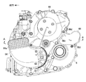
図1〜図6は本発明にかかる無段変速機の一例の具体的構造を示し、図7はその骨格構造を示す。
この実施例の無段変速機はFF横置き式の自動車用変速機であり、大略、エンジン出力軸1によりトーショナルダンパ2を介して駆動される入力軸3、駆動プーリ11を支持する駆動軸10、従動プーリ21を支持する従動軸20、駆動プーリ11と従動プーリ21に巻き掛けられた乾式のVベルト15、第1減速軸30、第2減速軸31、車輪と連結された出力軸32、変速用モータ40(図7参照)、テンショナ装置50などで構成されている。入力軸3,駆動軸10,従動軸20,第1減速軸30、第2減速軸31および出力軸32はいずれも非同軸で、かつ平行に配置されている。図1,図4では駆動プーリ11が従動プーリ21より上方に描かれているが、実際には図3に示すように駆動プーリ11が従動プーリ21より下方に配置されている。
この実施例で用いられるVベルト15は、一対の無端状張力帯と、これら張力帯に長さ方向に係止された多数のブロックとで構成された公知の複合ベルトである。
1 to 6 show a specific structure of an example of a continuously variable transmission according to the present invention, and FIG. 7 shows its skeleton structure.
The continuously variable transmission of this embodiment is an FF horizontal type automobile transmission, which is roughly an
The V-
入力軸3は軸受を介して変速機ケース6によって回転自在に支持され、入力軸3には、駆動軸10のエンジン側端部に設けられたギヤ10aに噛み合う入力ギヤ3aが一体に形成されている。入力ギヤ3aとギヤ10aとの減速比を適切に設定することで、ベルト駆動に適した減速比で駆動軸10を回転させることができる。
The
駆動プーリ11は、駆動軸10上に固定された固定シーブ11aと、駆動軸10上に軸方向移動自在に支持された可動シーブ11bと、可動シーブ11bの背後に設けられたストローク機構12とを備え、可動シーブ11bおよびストローク機構12はVベルト15よりエンジン側に配置されている。この実施例のストローク機構12は、変速用モータ40による回転入力によって可動シーブ11bを軸方向に移動させるボールネジ機構であり、可動シーブ11bに軸受12aを介して相対回転自在に支持された雌ねじ部材12bと、ケース6に固定された雄ねじ部材12cとを備え、雌ねじ部材12bの外周部には変速ギヤ13が固定されている。
The
従動プーリ21は、従動軸20上に固定された固定シーブ21aと、従動軸20上に軸方向移動自在に支持された可動シーブ21bと、可動シーブ21bの背後に設けられたストローク機構22とを備え、可動シーブ21bとストローク機構22はVベルト15より反エンジン側に配置されている。このストローク機構22も駆動プーリ11のストローク機構12と同様の構成を有するボールネジ機構であり、可動シーブ21bに軸受22aを介して相対回転自在に支持された雌ねじ部材22bと、ケース6に固定された雄ねじ部材22cとを備え、雌ねじ部材22bの外周部には変速ギヤ23が固定されている。
The driven
従動軸20の従動プーリ21よりエンジン側の部位には、前後進切替機構24が設けられ、その両側には前進用ギヤ25と後進用ギヤ26とが回転自在に支持されている。前後進切替機構24を図7の左側へシフトすると前進(D)位置になり、右側へシフトすると後進(R)位置となる。従動軸20のエンジン側の軸端部には発進クラッチ27が設けられ、発進クラッチ27は前後進切替機構24のハブ24aを従動軸20に対して断接する。前進用ギヤ25は第1減速軸30のギヤ30aに噛み合い、第1減速軸30のギヤ30bは第2減速軸31のギヤ31aに噛み合い、さらに第2減速軸31のギヤ31bは差動装置33のリングギヤ33aに噛み合っている。また、後進用ギヤ26はアイドラギヤ28を介して第1減速軸30のギヤ30bに噛み合っている。そして、差動装置33を介して車輪に連結された出力軸32を駆動している。
A forward /
上記入力軸3の入力ギヤ3a、駆動軸10のギヤ10a、前後進切替機構24、前進用ギヤ25、後進用ギヤ26、発進クラッチ27、第1減速軸30(ギヤ30a,30b)、第2減速軸31(ギヤ31a,31b)および差動装置33は、ケース6のエンジン側に形成されたギヤ室6a内に収容されている。このギヤ室6aは油で潤滑されている。
一方、駆動プーリ11と従動プーリ21は、ギヤ室6aと隔壁6cで仕切られたケース6のプーリ室6b内に配置されている。プーリ室6bは無潤滑空間であり、空冷されている。
The
On the other hand, the
ケース6の外側部に変速用モータ40(図7参照)が取り付けられている。変速用モータ40の出力ギヤ41は第1変速軸45の一端に設けられた減速ギヤ45aに噛み合っている。第1変速軸45はプーリ室6b内に架け渡して設けられている。第1変速軸45の他端部に設けられたギヤ45bは従動プーリ21の可動シーブ21bの移動ストローク分の長さを有する平歯車であり、従動プーリ21に設けられた変速ギヤ23と噛み合っている。第1変速軸45のギヤ45bを回転させると、変速ギヤ23が追随回転することでボールネジ機構22の作用により、可動シーブ21bを軸方向へ移動させることができる。つまり、変速用モータ40によって従動プーリ21のプーリ溝幅(ベルト巻き掛け径)を連続的に変化させることができる。
A speed change motor 40 (see FIG. 7) is attached to the outer side of the
従動プーリ21の変速ギヤ23は、ケース6に架け渡して設けられた第2変速軸46の第1アイドラギヤ46aとも噛み合い、さらに第2変速軸46の第2アイドラギヤ46bは駆動プーリ11の変速ギヤ13と噛み合っている。これらアイドラギヤ46a,46bも、第1変速軸45のギヤ45bと同様に、可動シーブ11b,21bの移動ストローク分の長さを有する平歯車で構成されている。第2変速軸46は、図3に示すように、駆動プーリ11と従動プーリ21との間であって、かつVベルト15の周回内に配置されている。変速用モータ40の回転力は、第1変速軸45,従動プーリ21の変速ギヤ23,第2変速軸46を介して駆動プーリ11の変速ギヤ13へと伝達される。そのため、駆動プーリ11の可動シーブ11aと従動プーリ21の可動シーブ21aは互いに同期し、かつ互いにプーリ溝幅(ベルト巻き掛け径)を逆方向に変化させながら軸方向へ移動することができる。
The
次に、Vベルト15にベルト張力を与える機構、すなわちテンショナ装置50について説明する。
上記のようにプーリ11,21のプーリ溝幅(ベルト巻き掛け径)は変速用モータ40によって相反方向に可変されるが、それだけでは伝達トルクによってVベルト15とプーリ11,21との間に滑りが発生してしまう。そこで、Vベルト15に滑りを発生させないだけのベルト張力を与えるため、図3に示されるようなテンショナ装置50が設けられている。テンショナ装置50はVベルト15の緩み側を内側に向かって押圧するテンションローラ51と、このテンションローラ51をリンク52を介して支持する揺動自在なテンショナアーム53とを備えている。このように外側から内側に向かってVベルト15を押圧することで、所定のベルト張力を得るとともに、プーリ11,21に対するVベルト15の巻き付け長さを長くし、伝達効率を高めている。
ここでは、テンションローラ51をリンク52を介してテンショナアーム53に取り付けたが、テンションローラ51をテンショナアーム53に直接取り付けてもよいことは勿論である。
また、テンションローラ51はVベルト15に対して外側から圧接するものに限らず、内側から圧接するものでもよい。
Next, a mechanism for applying belt tension to the V-
As described above, the pulley groove width (belt wrapping diameter) of the
Here, the
Further, the
テンショナアーム53の基端部は、軸53aを介して変速機ケース6に揺動自在に取り付けられている。テンショナアーム53の中間部には、軸54を介してピン55の基端部が回転自在に取り付けられている。ピン55の棒状の先端部は、プーリ室6bの下部に設けられた油圧シリンダ56のピストンロッド57の中空部に挿入され、中空部の底部に当接している。油圧シリンダ56の油圧を調整することで、テンショナアーム53の回動付勢力を制御し、ベルト駆動に適した最適なベルト張力に調整することができる。油圧シリンダ56内には圧縮バネ58が配置されており、圧縮バネ58のばね力は、たとえ油圧シリンダ56の油圧がフェールした場合でも、走行に必要な最低限のベルト張力を付与できるばね力に設定されている。
この実施例では、ベルト15に最低限の張力を付与するため、油圧シリンダ56内に圧縮バネ58を配置したが、テンショナアーム53を揺動付勢するためのバネを別に配置してもよい。この場合、バネとしては圧縮ばね以外に、引張バネや捩りバネを用いてもよい。
また、この実施例では、テンションローラ51がVベルト15を外側から内側に向かって押圧する例について説明したが、テンションローラ51がVベルト15を内側から外側に向かって押圧する場合でも適用可能である。
A base end portion of the
In this embodiment, the
In this embodiment, an example in which the
次に、上記無段変速機の冷却装置について説明する。
図1,図4に示すように、ケース6の反エンジン側の側壁を構成するケースカバー60には、駆動軸10の反エンジン側の軸端部を回転自在に支持した第1ベアリング70を保持する保持部61と、従動軸20の反エンジン側の軸端部を回転自在に支持した第2ベアリング71を保持する保持部62とが設けられている。図2に示すように、保持部61の周囲には、駆動軸10を中心として環状に配列された複数の吸気口63が設けられている。
Next, the cooling device for the continuously variable transmission will be described.
As shown in FIGS. 1 and 4, the case bearing 60 that forms the side wall of the
駆動プーリ11の固定シーブ11aおよび可動シーブ11bの外側面(背面)にはフィン11c,11dが形成されており、中でも固定シーブ11aの外側面のフィン11cは広幅に形成されている。吸気口63は固定シーブ11aの外側面に対面しており、フィン11cより内径側に配置されている。そのため、フィン11cによる遠心ポンプの作用により、吸気口63から外気が吸い込まれ、Vベルト15の外側へと送り込まれる。フィン11cは、ケースカバー60の内壁面と近接しているため、ケースカバー60とフィン11cとの隙間が狭くなり、フィン11cの回転による遠心ポンプ作用を効果的に働かせることができる。
ケースカバー60の外側面には、空気取入口64aから取り込んだ外気を吸気口63へ均等に導くための樹脂製の吸気ダクト64が固定されている。この実施例の空気取入口64aは、多量の空気が取り入れられるように広い面積に格子状に形成され、かつ変速機ケース6の側方へ開口している。
A resin-made
ケース6とケースカバー60との接合部であって、従動プーリ21の外周部近傍には、従動プーリ21のほぼ接線方向に開口する排気口65(図3,図5参照)が形成されている。この排気口65には樹脂製の排気ダクト66(図6参照)が接続されている。排気ダクト66には、排気口65に嵌合される筒型の嵌合部66aが形成され、この嵌合部66aのプーリ回転方向下流側には、ケース6内に突出し、その先端が従動プーリ21の外周部に近接する誘導部66bが一体に形成されている。誘導部66bは、ケース6内を流れた空気のケース6内への逆戻りを抑制し、排出方向に誘導する役割を有する。誘導部66bは、最大変速比(Low)の時でも従動プーリ21およびVベルト15と干渉せず、かつプーリ21およびVベルト15の外周にできるだけ近接するように、その外形形状に合わせてアンダーカットされている。
An exhaust port 65 (see FIGS. 3 and 5) that opens in a substantially tangential direction of the driven
排気ダクト66には、排気口65の外側面に当接するフランジ66cが一体に形成され、誘導部66bのケース6内への突出量を規定している。排気ダクト66には取付座66dが2箇所に設けられており、これら取付座66dはケース6の外側面にボルトで締結される。このとき、フランジ部66cが排気口65を塞ぐ形となるので、雨水やシャワー水が排気口65からケース6内に入るのを防止できる。なお、フランジ部66cと排気口65の外側面との間にパッキング等を介装すれば、さらに水入りを確実に防止できる。
The
従動プーリ21の固定シーブ21aおよび可動シーブ21bの外側面(背面)にもフィン21c,21dが形成されている。これらフィン21c,21dの回転により、プーリ室6b内を流れた空気は排気口65から外部へ排出される。このとき、空気の一部は排気口65から排出されずにフィン21c,21dに連れてプーリ室6b内に戻ろうとするが、この空気を排気口65のプーリ回転方向下流側からケース6内に突出した誘導部66bがせき止め、排出方向に誘導するため、空気を排気口65から効率よく排出することができる。
排気ダクト66は、排気口65との接続部近傍で横方向に屈曲しており、中間部がケース6の外側面に沿って横方向へ伸び、その先端には下方へ開口した開口部66eが形成されている(図6参照)。そのため、水等が排気ダクト66を通って排気口65に流れ込むのを防止できる。
The
従動プーリ21の固定シーブ21aの背後には、隔壁6cを介してギヤ室6aが設けられている。ギヤ室6aには潤滑油が封入されているため、油温上昇により、隔壁6cも温度上昇する。固定シーブ21aと隔壁6cとの間の空間であって、特に駆動プーリ11寄りの空間は、新気の流通が少ないため、熱がこもりやすく、その熱でプーリ室6bの室温も上昇してしまう。
そこで、この実施例では図4,図5に示すように、従動プーリ21の固定シーブ21aと対面する隔壁6cの側面に凹部80を設け、この凹部80に案内板81を架け渡して固定してある。案内板81の両端部が隔壁6cの側面にボルト82で固定されている。案内板81は固定シーブ21aのフィン21cとほぼ対向する位置に固定され、案内板81とフィン21cとの隙間は、1〜3mm程度の微小な隙間に設定されている。案内板81で仕切られた凹部80の一方の開口80aはフィン21cの内径側に開口しており、他方の開口80bは駆動プーリ側に開口している。そのため、フィン21cの回転に伴う遠心ポンプの作用により、図4,図5に矢印で示すように、空気は駆動プーリ側の開口80bから凹部80に入り、従動プーリ側の開口80aから固定シーブ21aの内径側に吸い出され、固定シーブ21aの外径側へと流れる。その後、従動プーリ21の回転に伴って排気口65へと排気される。
このように固定シーブ21aと隔壁6cとの間の空間に新気が導かれ、換気流量が増加するため、固定シーブ21aおよび隔壁6cが冷却され、さらにはギヤ室6aに封入された潤滑油の油温も低下する。そのため、プーリ室6b全体の冷却効果を高めることができる。
A
Therefore, in this embodiment, as shown in FIGS. 4 and 5, a
In this way, fresh air is introduced into the space between the fixed
上記凹部80の駆動プーリ側の開口80bの位置は、駆動プーリ11と従動プーリ21との間の領域、特にベルト15の周回領域と重なる領域に設けるのがよい。その理由は、この領域は新気の流通が少なく、空気の澱みが発生しやすいからである。したがって、この領域の空気を吸い込んで、強制的に従動プーリ21の内径側へ送り込むことで、空気の澱みを解消し、ひいてはベルトの温度上昇を抑制できる。
The position of the
上記のように、この無段変速機の冷却装置は、駆動プーリ11のフィン11cとケースカバー60の内壁面との隙間が狭いので、フィン11cの遠心ポンプ作用により、駆動プーリ11の内周側から外周側への空気の流れのみが発生し、吸気口63から空気を効率よく吸い込むことができる。
吸気口63から吸い込まれた空気は、駆動プーリ11の半径方向外側へ押し出され、Vベルト15の外側へと送り込まれる。そして、Vベルト15の動きにつれて従動プーリ21方向へ流れる。
さらに、従動プーリ21のフィン21c,21dの攪拌作用によって、空気はフィン21c,21dの回転につれて回転するが、排気ダクト66に設けられた誘導部66bによってプーリ室6b内に逆戻りする空気量が制限されるので、プーリ室6b内で温められた空気を排気口65から効率よく外部へ排気できる。
上記のように吸気口63からの吸気量および排気口65からの排気量が共に増加するので、プーリ室6bの換気流量が増加し、Vベルト15およびプーリ11,21を効果的に冷却できる。
As described above, the cooling device for the continuously variable transmission has a narrow gap between the
The air sucked from the
Furthermore, the air rotates as the
As described above, both the intake air amount from the
本発明は上記実施例に限定されるものではない。
上記実施例では、吸気口63を駆動プーリ11の近傍に設け、排気口65を従動プーリ21の近傍に設けたが、これとは逆に、吸気口63を従動プーリ21の近傍に設け、排気口65を駆動プーリ11の近傍に設けてもよい。
上記実施例では、吸気口63が駆動プーリ11の固定シーブ11aの背面側であって、固定シーブ11aのフィン11cより内径側に開口しており、かつケースカバー60の内壁面がフィン11cに近接しているため、遠心ポンプの作用によって外気を効率よく吸い込むことができ、ケースカバー60の内面に案内板を取り付ける必要はないが、吸気口63が駆動プーリ11の外周部近傍に設けられている場合には、固定シーブ11aのフィン11cに近接する案内板をケースカバー60の内面に取り付けてもよい。
また、上記実施例では、各プーリに設けられたストローク機構および変速用モータと、Vベルトをテンションローラで押圧してベルト張力を得るテンショナ装置とを組み合わせた無段変速機について説明したが、これに限るものではなく、公知のあらゆる方式の乾式無段変速機に適用できる。
The present invention is not limited to the above embodiments.
In the above embodiment, the
In the above embodiment, the
In the above embodiment, a continuously variable transmission is described in which a stroke mechanism and a speed change motor provided in each pulley are combined with a tensioner device that obtains belt tension by pressing a V belt with a tension roller. The present invention is not limited to this, and can be applied to all known dry-type continuously variable transmissions.
6 ケース(ケーシング)
6a ギヤ室
6b プーリ室
6c 隔壁(側壁)
11 駆動プーリ
15 Vベルト
21 従動プーリ
21a 固定シーブ
21c フィン
60 ケースカバー(ケーシング)
63 吸気口
65 排気口
80 凹部(隙間)
80a 従動プーリ側の開口
80b 駆動プーリ側の開口
81 案内板
6 Case (casing)
11 Drive pulley 15
63
80a Opening on the driven
Claims (2)
上記駆動プーリおよび従動プーリのうち少なくとも一方のプーリの固定シーブの背面には、気流を発生させるフィンが設けられており、
上記フィンと、上記固定シーブの背面と対向するケーシングの側壁との間には隙間が設けられ、
上記隙間には上記フィンに近接して案内板が配置され、
上記案内板と上記側壁との間の空間は、上記フィンより内径側に開口していることを特徴とするベルト式無段変速機の冷却装置。 The casing that covers the driving pulley and the driven pulley and the V belt wound between the pulleys is provided with an intake port and an exhaust port. Air is sucked from the intake port as the pulleys rotate, In belt type continuously variable transmissions that exhaust air,
On the back surface of the fixed sheave of at least one of the driving pulley and the driven pulley, a fin for generating an airflow is provided,
A gap is provided between the fin and the side wall of the casing facing the back surface of the fixed sheave,
In the gap, a guide plate is arranged close to the fin,
A cooling device for a belt-type continuously variable transmission, wherein a space between the guide plate and the side wall opens toward the inner diameter side of the fin.
Priority Applications (1)
| Application Number | Priority Date | Filing Date | Title |
|---|---|---|---|
| JP2004104271A JP2005291274A (en) | 2004-03-31 | 2004-03-31 | Cooling device for belt-type continuously variable transmission |
Applications Claiming Priority (1)
| Application Number | Priority Date | Filing Date | Title |
|---|---|---|---|
| JP2004104271A JP2005291274A (en) | 2004-03-31 | 2004-03-31 | Cooling device for belt-type continuously variable transmission |
Publications (1)
| Publication Number | Publication Date |
|---|---|
| JP2005291274A true JP2005291274A (en) | 2005-10-20 |
Family
ID=35324445
Family Applications (1)
| Application Number | Title | Priority Date | Filing Date |
|---|---|---|---|
| JP2004104271A Pending JP2005291274A (en) | 2004-03-31 | 2004-03-31 | Cooling device for belt-type continuously variable transmission |
Country Status (1)
| Country | Link |
|---|---|
| JP (1) | JP2005291274A (en) |
Cited By (2)
| Publication number | Priority date | Publication date | Assignee | Title |
|---|---|---|---|---|
| CN102889374A (en) * | 2012-10-29 | 2013-01-23 | 浙江信阳实业有限公司 | All-terrain vehicle stepless speed change cooling system device |
| CN103899740A (en) * | 2014-03-25 | 2014-07-02 | 重庆隆鑫发动机有限公司 | CVT (constant-voltage transformer) transmission structure assembly and motorcycle |
-
2004
- 2004-03-31 JP JP2004104271A patent/JP2005291274A/en active Pending
Cited By (2)
| Publication number | Priority date | Publication date | Assignee | Title |
|---|---|---|---|---|
| CN102889374A (en) * | 2012-10-29 | 2013-01-23 | 浙江信阳实业有限公司 | All-terrain vehicle stepless speed change cooling system device |
| CN103899740A (en) * | 2014-03-25 | 2014-07-02 | 重庆隆鑫发动机有限公司 | CVT (constant-voltage transformer) transmission structure assembly and motorcycle |
Similar Documents
| Publication | Publication Date | Title |
|---|---|---|
| US7427248B2 (en) | Continuously variable transmission | |
| US7686123B2 (en) | Straddle-type vehicle with belt type continuously variable transmission having resin-block-type belt | |
| US4631977A (en) | Power transmission casing in motorized two-wheeled vehicle | |
| JP5290029B2 (en) | Internal combustion engine | |
| US7487853B2 (en) | Saddle-type vehicle | |
| WO2003085285A1 (en) | Engine | |
| JP2002104276A (en) | Power unit of motorcycle | |
| JP2005315270A (en) | V-belt type automatic transmission | |
| JP2005291274A (en) | Cooling device for belt-type continuously variable transmission | |
| JP2005291273A (en) | Cooling device for belt-type continuously variable transmission | |
| JP2004360881A (en) | Cooling structure for continuously variable transmission | |
| JP2006029486A (en) | Cooling device for belt type continuously variable transmission | |
| JP2007100815A (en) | Belt transmission device | |
| JPS61274170A (en) | Cooling apparatus for v-belt type automatic transmission | |
| JPH0526328A (en) | Swing case cooling structure of unit swing type engine | |
| JP2004286047A (en) | Cooling structure for continuously variable transmission | |
| JP5436005B2 (en) | Transmission air guide structure | |
| JP2007177689A (en) | Power unit | |
| JPH0321728B2 (en) | ||
| JP2003287110A (en) | Cooling system for continuously variable transmission | |
| JP5303340B2 (en) | Internal combustion engine with kick starter | |
| JPH0314957A (en) | Auxialialy unit drive device for vehicle | |
| JPS6113093B2 (en) | ||
| JPS61282666A (en) | Belt transmission apparatus | |
| JPS58137663A (en) | Cooling device for belt type power transmitting device |