JP2005291230A - Pipe connection connector - Google Patents
Pipe connection connector Download PDFInfo
- Publication number
- JP2005291230A JP2005291230A JP2004102882A JP2004102882A JP2005291230A JP 2005291230 A JP2005291230 A JP 2005291230A JP 2004102882 A JP2004102882 A JP 2004102882A JP 2004102882 A JP2004102882 A JP 2004102882A JP 2005291230 A JP2005291230 A JP 2005291230A
- Authority
- JP
- Japan
- Prior art keywords
- retainer
- pipe
- connector
- retainer holding
- main body
- Prior art date
- Legal status (The legal status is an assumption and is not a legal conclusion. Google has not performed a legal analysis and makes no representation as to the accuracy of the status listed.)
- Pending
Links
Images


Landscapes
- Quick-Acting Or Multi-Walled Pipe Joints (AREA)
Abstract
【課題】 コネクタ本体にパイプを着脱可能に連結するコネクタであって、コネクタ本体のリテーナ保持部に、リテーナを介してパイプを「ガタ」なく連結することができると共にリテーナ保持部内に塵埃などの異物が侵入するのを防止する。
【解決手段】 パイプPを貫通支持するリテーナRを収容保持した、コネクタ本体Cのリテーナ保持部10を弾性ブーツBで被覆し、この弾性ブーツBで、パイプPと、リテーナ保持部10およびリテーナRとの間の「ガタ」をなくした。
【選択図】 図1
PROBLEM TO BE SOLVED: To connect a pipe to a connector body in a detachable manner, the pipe can be connected to a retainer holding part of the connector body through the retainer without "gap" and foreign matter such as dust in the retainer holding part Prevent intrusion.
A retainer holding portion 10 of a connector main body C that accommodates and holds a retainer R that penetrates and supports a pipe P is covered with an elastic boot B. With the elastic boot B, the pipe P, the retainer holding portion 10 and the retainer R are covered. The “back” between them was lost.
[Selection] Figure 1
Description
本発明は、2本の配管の接続用、たとえば、燃料タンクからエンジン本体の燃料供給部に燃料を送給する燃料配管の接続用コネクタに関するものである。 The present invention relates to a connector for connecting two pipes, for example, a connector for connecting a fuel pipe for supplying fuel from a fuel tank to a fuel supply part of an engine body.
従来、一方の配管を接続する雌部材(コネクタ本体)と、他方の配管である雄部材とを着脱可能に接続するにあたり、雄部材に装着した保持部材(リテーナ)を、雌部材の窓部内に軸方向から着脱自在に嵌着するようにしたコネクタが既に知られている。
ところが、この種のコネクタは、雌部材と雄部材との着脱が容易かつ迅速に行われるように構成されるため、雌部材と雄部材との連結状態では、その連結部に径方向および軸方向の「ガタ」が存するのを避けられず、また、前記雌部材に開口される窓部が外部に露出状態となるため、この窓部から連結部内に塵埃などの異物が侵入するのを避けられず、このため、雌部材と雄部材との強固な連結が難しくなるばかりでなく、「ガタ」に起因して異音が発生し、さらに、異物の侵入で両部材の着脱操作に支障を及ぼすなどの問題があった。 However, this type of connector is configured so that the female member and the male member can be easily and quickly attached and detached. Therefore, in the connected state between the female member and the male member, the connecting portion has a radial direction and an axial direction. In addition, since the window portion opened in the female member is exposed to the outside, foreign substances such as dust can be prevented from entering the connecting portion from the window portion. For this reason, not only is it difficult to firmly connect the female member and the male member, but an abnormal noise is generated due to "backlash", and further, the intrusion of the foreign matter impedes the attaching / detaching operation of both members. There were problems such as.
本発明はかかる実情に鑑みてなされたものであり、一方の接続配管を接続したコネクタ本体のリテーナ保持部に、リテーナに装着される他方の配管を「ガタ」なく連結でき、しかもその連結部への異物の侵入を防止するようにした、新規な配管接続用コネクタを提供することを目的とするものである。 The present invention has been made in view of such a situation, and the other pipe attached to the retainer can be connected to the retainer holding part of the connector main body to which one of the connection pipes is connected without any play, and to the connection part. An object of the present invention is to provide a novel connector for pipe connection that prevents intrusion of foreign matter.
上記目的を達成するために、請求項1の発明は、一方の接続配管に接続されるコネクタ本体と、他方の接続配管に装着されて前記コネクタ本体の一端に形成されるリテーナ保持部内に着脱可能に保持されるリテーナと、前記リテーナ保持部を被覆する弾性ブーツとを備え、前記弾性ブーツは、前記リテーナ保持部の外周を被覆する両端開放の筒状胴部と、その胴部の両端より径方向内方に折り返される第1および第2の内向き折返し部とを有し、それらの内向き折返し部は、前記リテーナ保持部の端部およびリテーナの端部にそれぞれ密着係合してそれらを軸方向に弾発挟持すると共に前記第1の内向き折返し部は、前記リテーナに装着される他方の接続配管の外面と、リテーナおよびリテーナ保持部間に弾発挟入されることを特徴としている。 In order to achieve the above object, the invention of claim 1 is detachable into a connector main body connected to one connection pipe and a retainer holding part formed at one end of the connector main body attached to the other connection pipe. And an elastic boot that covers the retainer holding portion. The elastic boot has a cylindrical barrel portion that is open at both ends that covers the outer periphery of the retainer holding portion, and a diameter that is larger than both ends of the barrel portion. First and second inwardly folded portions that are folded inward in the direction, and the inwardly folded portions are in close contact with the end portion of the retainer holding portion and the end portion of the retainer, respectively. The first inward turn-back portion is elastically sandwiched between the outer surface of the other connecting pipe attached to the retainer and the retainer and the retainer holding portion. .
請求項1の発明の特徴によれば、弾性ブーツをコネクタ保持部に被せることで、コネクタ本体のリテーナ保持部に、リテーナを介して接続配管を「ガタ」なく連結することができると共にリテーナ保持部内に塵埃などの異物が侵入するのを防止することができる。 According to the feature of the invention of claim 1, by covering the connector holding portion with the elastic boot, the connecting pipe can be connected to the retainer holding portion of the connector body via the retainer without "backlash" and the retainer holding portion It is possible to prevent foreign matter such as dust from entering the battery.
以下、本発明の実施の形態を、添付図面に示した本発明の実施例に基づいて以下に具体的に説明する。 DESCRIPTION OF THE PREFERRED EMBODIMENTS Embodiments of the present invention will be specifically described below based on examples of the present invention shown in the accompanying drawings.
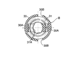
添付図面において、図1は、配管接続用コネクタの縦断側面図、図2は、図1の2−2線に沿う断面図、図3は、配管接続用コネクタの分解縦断側面図、図4は、配管接続用コネクタの分解斜視図、図5は、図3の5線矢視の弾性ブーツの端面図、図6は、図5の6−6線に沿う弾性ブーツの断面図、図7は、図6の7−7線に沿う弾性ブーツの断面図である。
In the attached drawings, FIG. 1 is a longitudinal side view of a connector for pipe connection, FIG. 2 is a sectional view taken along line 2-2 of FIG. 1, FIG. 3 is an exploded side view of the connector for pipe connection, and FIG. FIG. 5 is an exploded perspective view of the connector for pipe connection, FIG. 5 is an end view of the elastic boot taken along
本発明にかかる配管接続用コネクタは、コネクタ本体Cと、これに着脱時自在に連結されるリテーナRと、コネクタ本体Cのリテーナ保持部の外周を被覆する弾性ブーツBとより構成され、合成樹脂製のコネクタ本体Cには、互いに接続される2本の接続配管の一方である、合成樹脂製の可撓性チューブTが接続され、また、同じく合成樹脂製のリテーナRには、互いに接続される2本の接続配管の他方である、金属製のパイプPが貫通装着される。パイプPの外周面には、リテーナRに係合されるフランジ状の係合凸部Pfと、後述する弾性ブーツBの第1の内向き折返し部31が密着されるテーパー面Ptが形成される。
The connector for pipe connection according to the present invention includes a connector main body C, a retainer R that is detachably coupled to the connector main body C, and an elastic boot B that covers the outer periphery of the retainer holding portion of the connector main body C. The connector body C made of plastic is connected to a flexible tube T made of synthetic resin, which is one of two connecting pipes connected to each other, and is also connected to the retainer R made of synthetic resin. A metal pipe P, which is the other of the two connection pipes, is inserted through. On the outer peripheral surface of the pipe P, there is formed a tapered surface Pt in which a flange-like engaging convex portion Pf engaged with the retainer R and a first
前記コネクタ本体Cは、本発明にかかる配管接続用コネクタの主体部分を構成しており、全体として基端側、すなわちリテーナRの保持側から先端側、すなわちチューブTの接続側に向けて漸次小径となる細長い筒状に形成されており、その基端側から先端側に向けてリテーナ保持部10、中間部11、およびチューブ接続部12が順に小径になるように段状に一体に形成されている。そして、リテーナ保持部10と中間部11との間には、本発明にかかる弾性ブーツB(後に詳述)の第2の内向き折返し部32が密着係合される段部13が形成されている。
The connector body C constitutes a main part of the connector for pipe connection according to the present invention, and as a whole gradually decreases in diameter from the proximal end side, that is, the holding side of the retainer R toward the distal end side, that is, the connecting side of the tube T. The
前記リテーナ保持部10は、リテーナRを収容保持すべくソケット状に形成され、その端部にリテーナRと係合し得る係止端部10Aが形成され、また、その中間部に90°の位相差で対をなす四角な窓孔10B,10Bが開口されている。さらに、リテーナ保持部10の内面には、後述のリテーナRの回り止め凹部21Bと係合する回り止め突起10Cが形成されている。リテーナ保持部10の奥部内周面には、ブッシュ15が嵌着される。また、コネクタ本体Cの中間部11は、径大部と径小部とを有して中空円筒状に形成されており、その径大部側の内周面にはスペーサ17を挟んで一対のOリング16,16が嵌着されており、図1,2に示すように、ブッシュ15および一対のOリング16,16は、リテーナ保持部10に挿嵌される、金属製パイプPの外周面を流体密にシールする。
The
コネクタ本体Cのチューブ接続部12は、細長い中空円筒状に形成されていて、前記チューブTが圧入接続される部分であり、その外周面には軸方向に間隔をあけて断面鋸歯状の複数の環状抜止突起12A…が一体に突設され、さらに、その先部には環状溝12Bが形成され、該環状溝12BににOリング19が嵌着されている。図1,2に示すように、コネクタ本体Cは、このチューブ接続部12をチューブT内に圧入することによって、チューブTに接続される。このとき、チューブTは、合成樹脂製であることから、その弾性により膨出変形され、前記複数の環状抜止突起12A…は、チューブTの内面に食い込んで、チューブTの妄りな抜け出しを防止すると共にOリング19はチューブ接続部12と、チューブTとの間を流体密にシールする。
The
前記リテーナRは、中空の截頭円錐形状に形成され、その一側面は面取りされて、その全長に亘って切欠部20が開口されて横断面C字状に形成され、その切欠部20と対面する壁部分を支点として径方向に開閉可能である。図1,2に示すように、リテーナRは、その先部に、金属製パイプPのフランジ状係合凸部Pfを係合固定させるための、一対の係合孔21A,21Aを有する係合凹部21が形成され、また、その基部に、コネクタ本体Cの係止端部10Aに対して径方向内側から嵌合されて軸方向に係止される係止溝22が形成されている。リテーナRは、その係止溝22を、リテーナ保持部10の係止端部10Aに係合させることで、コネクタ本体Cに対して軸方向に移動しないように保持される。また、このリテーナRは、その内周面に雌テーパー面23が形成されると共のその先部外周に雄テーパー面24が形成されており、雌テーパー面23は、パイプPをリテーナR内に軸方向から挿入したとき、その係合凸部Pfと当接してその移動を案内すると共に係合凸部Pfの軸方向の移動に伴ってリテーナRを拡開させて係合凸部Pfの通過を許容する。そして、図1,2に示すように係合凸部Pfが、係合凹部21に至ったところでリテーナRは元に位置に復元して係合凸部Pfは係合凹部21に嵌合して、パイプPは、リテーナRに軸方向の移動を規制されて連結される。一方、前記雄テーパー面24は、リテーナRをコネクタ本体Cのリテーナ保持部10に軸方向から挿入する際に、コネクタ本体Cの係止端部10Aとの当接により、リテーナRを全体的に縮径変形させ、この縮径変形に伴って係止溝22を係止端部10Aに係合させることができる。さらに、リテーナRの係合凹部21の内面には、前記リテーナ保持部10の回り止め突起10Cと係脱可能に係合する回り止め凹部21B(図3参照)が形成されている。
The retainer R is formed in a hollow frustoconical shape, and one side surface thereof is chamfered, and a
リテーナRの基端部には、操作つまみ25が形成されており、この操作つまみ25を径方向内方に加圧することにより、リテーナRを縮径させることができ、これをコネクタ本体Cのリテーナ保持部10に組み付け易くしている。
An
この実施例にかかるコネクタでは、リテーナRをコネクタ本体Cのリテーナ保持部10に保持させてからパイプPをリテーナRの内部にその軸方向から挿入する。このとき、リテーナRはパイプPのフランジ状係合凸部Pfにより、径方向に拡開される。そして、その係合凸部Pfが、リテーナRの係合凹部21に至ったところで、リテーナRは、その弾性で縮径変形して、図1,2に示すように、フランジ状の係合凸部Pfは、リテーナRの係合凹部21に係合され、パイプPは、リテーナRに対して軸方向の移動を規制されて組み付けられる。
In the connector according to this embodiment, the retainer R is held by the
前記ブッシュ15および一対Oリング16,16はシール部材として機能するものであり、図1,2に示すように、コネクタ本体C内に金属製のパイプPが挿入されたとき、ブッシュ15および一対Oリング16,16が、パイプPの挿入端部の外周面に流体密に接触して、コネクタ本体Cと、パイプPとの間を流体密にシールする。
The
コネクタ本体Cのチューブ接続部12には、他の接続配管である、合成樹脂製の可撓性チューブTが、その軸方向から圧入され、このチューブTは、コネクタ本体Cのチューブ接続部12に接続される。そして、この接続状態では、複数の環状抜突起12Aは、チューブTの妄りな抜け出しを防止し、またOリング12は、コネクタ本体Cのチューブ接続部12と、チューブTとの間を流体密にシールする。
A flexible tube T made of synthetic resin, which is another connection pipe, is press-fitted from the axial direction into the
つぎに、図1〜4に、図5〜7を併せ参照して本発明に従う弾性ブーツBについて説明する。 Next, the elastic boot B according to the present invention will be described with reference to FIGS.
弾性ブーツBはゴムもしくは合成樹脂製であって、コネクタ本体Cのリテーナ保持部10の外周面を被覆し、パイプP、リテーナRおよびリテーナ保持部10間に存する「ガタ」を吸収すると共にリテーナ保持部10に開口される窓孔10B,10Bを被覆して、リテーナ保持部10内に塵埃などの異物が進入するのを防止するよにしたものである。 この弾性ブーツBは両端が開放され、コネクタ本体C側に向けて漸次小径となる中空円筒状をなす胴部30と、その胴部30の大径側の端面より径方向内側に略直角に折り返されるフランジ状の第1の内向き折返し部31と、前記胴部30の小径側端面より径方向内側に略直角に折り返される同じくフランジ状の第2の内向き折返し部32とを備え、第1の内向き折返し部31は、第2の内向き折返し部32よりも肉厚で、かつ径方向に長く形成されており、その遊端には玉縁状の膨大部31Aが一体に形成されている。図6,7に明瞭示すように、前記胴部30の径方向に対向す部分には、所定の幅にわたり他の部分よりも肉厚な一対の肉厚部30A,30Aが形成され、これらの肉厚部30A,30Aの両端は、前記第1および第2の内向き折返し部31,32に連続している。また、胴部30の第1の内向き折返し部31側の端部には、前記肉厚部と略90°の位相差を存して対をなす嵌込孔30B,30B2が開口されている。
The elastic boot B is made of rubber or synthetic resin, covers the outer peripheral surface of the
つぎに、この実施例の作用について説明する。 Next, the operation of this embodiment will be described.
コネクタは、たとえば、図1に示すように、車両用燃料タンクに接続されるパイプPと、車両用エンジンの燃料供給部に接続されるチューブTとを接続するのに用いられる。 For example, as shown in FIG. 1, the connector is used to connect a pipe P connected to a vehicle fuel tank and a tube T connected to a fuel supply part of the vehicle engine.
コネクタ本体Cのリテーナ保持部10内に、リテーナRを保持した状態において、それらの軸方向からその小径側端面を前方にしてリテーナ保持部10の外周に弾性ブーツBを挿嵌すれば、図1,2に示すように、前記リテーナRを保持したリテーナ保持部10は、弾性ブーツBにより被覆される。弾性ブーツBの第2の内向き折返し部32は、リテーナ保持部10の内側端縁、すなわち段部13に密着係合すると共にこれに続く弾性ブーツBの内周面がリテーナ保持部10の外周面に密着する。ここで、パイプPを前述したように、リテーナ保持部10に、その軸方向から連結すれば、第1の内向き折返し部31は、リテーナRの端縁に密着係合し、第2の内向き折返し部32と協働してリテーナ保持部10とリテーナRとを軸方向より弾発挟持する。また、膨大部31Aを有する第1の内向き折返し部31の一部分が、図1に示すように、リテーナRの端縁とパイプPのテーパー面Ptの外周間に圧縮されつつ挟入されると同時にその第1の内向き折返し部31の他の部分が、図2に示すように、リテーナ保持部10の端縁とパイプPのテーパー面Ptの外周間に圧縮されつつ挟入され、さらに、弾性ブーツBに開口される一対の嵌込孔30B,30B内には、リテーナRのフランジ状操作つまみ25が嵌め込まれ、弾性ブーツBの第1の内向き折返し部31は、パイプPと、リテーナRおよびリテーナ保持部10間に密に挟入される。以上により、ブーツBは、パイプP、リテーナ保持部10およびリテーナR間に存する、軸方向および径方向の「ガタ」をいずれも吸収することができ、コネクタ本体Cと、パイプPとの連結を一層強固なものとし、また「ガタ」による異音の発生を防止することができる。また、弾性ブーツBはリテーナ保持部10の窓孔10B,10Bを含む外周面を被覆することができるので、コネクタ本体CとパイプPとの連結部内への塵埃などの侵入を防止することができる。
If the retainer R is held in the
また、弾性ブーツBは、その中間部を内方に押圧すれば、第1および第2の内向き折返し部31,32は、リテーナRおよびリテーナ保持部10との連結部から外れて外側に反転されるので、該弾性ブーツBをそれらの連結部から容易に外すことができる。
In addition, if the elastic boot B is pressed inward at its intermediate portion, the first and second inwardly folded
以上、本発明の実施例について説明したが、本発明はその実施例に限定されることなく、本発明の範囲内で種々の実施例が可能である。 As mentioned above, although the Example of this invention was described, this invention is not limited to the Example, A various Example is possible within the scope of the present invention.
10・・・・・リテーナ保持部
30・・・・・胴部
31・・・・・第1の内向き折返し部
32・・・・・第2の内向き折返し部
B・・・・・・弾性ブーツ
C・・・・・・コネクタ本体
P・・・・・・接続配管(パイプ)
R・・・・・・リテーナ
T・・・・・・接続配管(チューブ)
10...
R ··· Retainer T ··· Connection piping (tube)
Claims (1)
前記弾性ブーツ(B)は、前記リテーナ保持部(10)の外周を被覆する両端開放の筒状胴部(30)と、その胴部(30)の両端より径方向内方に折り返される第1および第2の内向き折返し部(31,32)とを有し、それらの内向き折返し部(31,32)は、前記リテーナ保持部(10)の端部およびリテーナ(R)の端部にそれぞれ密着係合してそれらを軸方向に弾発挟持すると共に前記第1の内向き折返し部(31)は、前記リテーナ(R)に装着される他方の接続配管(P)の外面と、リテーナ(R)およびリテーナ保持部(10)間に弾発挟入されることを特徴とする、配管接続用コネクタ。
A connector main body (C) connected to one connection pipe (T) and a retainer holding part (10) attached to the other connection pipe (P) and formed at one end of the connector main body (C) are attached and detached. A retainer (R) that can be held; and an elastic boot (B) that covers the retainer holding portion (10).
The elastic boot (B) includes a cylindrical body part (30) with both ends open covering the outer periphery of the retainer holding part (10), and a first folded back radially inward from both ends of the body part (30). And the second inwardly folded portion (31, 32), and the inwardly folded portion (31, 32) is provided at the end of the retainer holding portion (10) and the end of the retainer (R). The first inward turn-back portion (31) and the retainer (R) are connected to the outer surface of the other connecting pipe (P) and the retainer (R), respectively. (R) and the retainer holding part (10) are elastically inserted between the connectors for pipe connection.
Priority Applications (1)
| Application Number | Priority Date | Filing Date | Title |
|---|---|---|---|
| JP2004102882A JP2005291230A (en) | 2004-03-31 | 2004-03-31 | Pipe connection connector |
Applications Claiming Priority (1)
| Application Number | Priority Date | Filing Date | Title |
|---|---|---|---|
| JP2004102882A JP2005291230A (en) | 2004-03-31 | 2004-03-31 | Pipe connection connector |
Publications (1)
| Publication Number | Publication Date |
|---|---|
| JP2005291230A true JP2005291230A (en) | 2005-10-20 |
Family
ID=35324409
Family Applications (1)
| Application Number | Title | Priority Date | Filing Date |
|---|---|---|---|
| JP2004102882A Pending JP2005291230A (en) | 2004-03-31 | 2004-03-31 | Pipe connection connector |
Country Status (1)
| Country | Link |
|---|---|
| JP (1) | JP2005291230A (en) |
-
2004
- 2004-03-31 JP JP2004102882A patent/JP2005291230A/en active Pending
Similar Documents
| Publication | Publication Date | Title |
|---|---|---|
| CN1322263C (en) | Rotatable quick connector | |
| AU2007240189B2 (en) | Improvements in or relating to tube couplings | |
| JP3724360B2 (en) | connector | |
| US20040066034A1 (en) | Connection verifying device and connection verifying structure for a pipe and a connector | |
| US20060214420A1 (en) | Quick connector | |
| JP2002013684A (en) | Quick connector | |
| JP2004144297A (en) | Anti-rotation device for connector, and anti-rotation structure for connector | |
| JP5027333B2 (en) | Corrugated tube connector | |
| US7547048B2 (en) | Fluid quick connector with integral pivotal retainer | |
| JPH07253185A (en) | Quick connector | |
| US7328922B2 (en) | Quick connector | |
| JP2001074185A (en) | Piping fittings | |
| JP2005291230A (en) | Pipe connection connector | |
| JP2016200159A (en) | Pipe joint | |
| US20060113792A1 (en) | Quick connector fluid coupling | |
| JP4034433B2 (en) | Tube connection structure | |
| JP2006300127A (en) | Stop | |
| JP4842019B2 (en) | Piping connection structure | |
| JP5207906B2 (en) | Fitting for flexible tube | |
| JP2004183703A (en) | Piping joint | |
| JP5784811B1 (en) | Fitting and fitting mounting structure | |
| JP2005054857A (en) | Structure for preventing fall of gasket for pipe fitting | |
| JP5967271B2 (en) | Fitting and fitting mounting structure | |
| JP2008261450A (en) | connector | |
| CN210770891U (en) | Plastic connector |