JP2005291183A - Oil quantity control device for internal combustion engine - Google Patents
Oil quantity control device for internal combustion engine Download PDFInfo
- Publication number
- JP2005291183A JP2005291183A JP2004111415A JP2004111415A JP2005291183A JP 2005291183 A JP2005291183 A JP 2005291183A JP 2004111415 A JP2004111415 A JP 2004111415A JP 2004111415 A JP2004111415 A JP 2004111415A JP 2005291183 A JP2005291183 A JP 2005291183A
- Authority
- JP
- Japan
- Prior art keywords
- lubricating oil
- valve
- internal combustion
- oil
- temperature
- Prior art date
- Legal status (The legal status is an assumption and is not a legal conclusion. Google has not performed a legal analysis and makes no representation as to the accuracy of the status listed.)
- Pending
Links
Images
Landscapes
- Lubrication Of Internal Combustion Engines (AREA)
Abstract
【課題】 内燃機関の全運転領域において、必要とされる量の潤滑油を供給することができる内燃機関の給油量制御装置を提供する。
【解決手段】 給油量制御装置1は、潤滑油をエンジン10のロッカーアーム25,26などに供給する動弁系潤滑油通路29と、動弁系潤滑油通路29に設けられ、ロッカーアーム25,26などに供給される潤滑油の給油量を調節する電磁弁40と、潤滑油の温度を検出する油温センサ52と、エンジン10のエンジン回転数を検出するクランク角センサ51と、油温センサ52により検出された潤滑油温度及びクランク角センサ51により検出されたエンジン回転数に基づいて、電磁弁40を制御するするECU50とを備える。
【選択図】 図1
PROBLEM TO BE SOLVED: To provide an oil supply amount control device for an internal combustion engine capable of supplying a required amount of lubricating oil in the entire operation region of the internal combustion engine.
An oil supply amount control device (1) is provided in a valve operating system lubricant passage (29) for supplying lubricating oil to rocker arms (25, 26) of an engine (10), and the valve operating system lubricant passage (29). An electromagnetic valve 40 that adjusts the amount of lubricating oil supplied to the engine 26, an oil temperature sensor 52 that detects the temperature of the lubricating oil, a crank angle sensor 51 that detects the engine speed of the engine 10, and an oil temperature sensor. ECU 50 for controlling the electromagnetic valve 40 based on the lubricating oil temperature detected by the engine 52 and the engine speed detected by the crank angle sensor 51.
[Selection] Figure 1
Description
本発明は、内燃機関の給油量制御装置に関する。 The present invention relates to an oil supply amount control apparatus for an internal combustion engine.
従来から、潤滑油ポンプで加圧された潤滑油を内燃機関の動弁系に圧送する潤滑装置が知られている(例えば、特許文献1参照)。 2. Description of the Related Art Conventionally, a lubricating device that pressure-feeds lubricating oil pressurized by a lubricating oil pump to a valve operating system of an internal combustion engine is known (see, for example, Patent Document 1).
特許文献1記載の潤滑装置では、潤滑油の圧力に応じて開閉される油圧作動弁が弁軸潤滑油路に設けられている。この油圧作動弁は、油圧が低い場合に開弁側に作動し、油圧が高い場合に閉弁側に作動する。内燃機関の低速回転時には、潤滑ポンプの回転速度が低く油圧が低いため、油圧作動弁が開弁側に作動する。この場合、潤滑油が油圧作動弁を介して圧送され、動弁系を構成する弁軸などが強制潤滑される。一方、内燃機関の高速回転時には、潤滑ポンプの回転速度が高く油圧が高いため、油圧作動弁が閉弁側に作動し、弁軸などの強制潤滑が停止される。このとき、弁軸などは、例えば、ロッカーアームの軸受部から漏れ、バルブスプリングの挙動に煽られて飛散し、飛沫となった潤滑油によってミスト潤滑される。
上記潤滑装置では、油圧作動弁が内燃機関の回転数によって変化する潤滑油の圧力に応じて開閉されるため、内燃機関の暖機が完了する前に内燃機関が高速回転される暖機前加速時や、無負荷状態で内燃機関が高速回転されるレーシング時などでは強制潤滑が停止されミスト潤滑がおこなわれる。 In the above lubricating device, the hydraulically operated valve is opened and closed in accordance with the pressure of the lubricating oil that changes depending on the number of revolutions of the internal combustion engine, so that the internal combustion engine is rotated at a high speed before the warming up of the internal combustion engine is completed. At the time of racing or when the internal combustion engine is rotated at high speed without load, forced lubrication is stopped and mist lubrication is performed.
暖機完了前の低油温時には、潤滑油の粘度が高いため、潤滑油が飛散しにくく、飛沫になりにくい。そのため、ミスト潤滑では暖機前加速時に給油量が不足するおそれがある。また、レーシング時には、信頼性確保の観点から多量の潤滑油が必要とされるが、ミスト潤滑では給油量が不足するおそれがあり、信頼性の確保が困難である。このように、特許文献1記載の潤滑装置では、強制潤滑がおこなわれるべき運転状態においてミスト潤滑がおこなわれることにより、必要とされる量に対して潤滑油の供給量が不足するおそれがある。
At the time of low oil temperature before the completion of warming up, the lubricating oil is high in viscosity, so that the lubricating oil is difficult to splash and splash. Therefore, in mist lubrication, there is a possibility that the amount of oil supply will be insufficient during acceleration before warm-up. In racing, a large amount of lubricating oil is required from the viewpoint of ensuring reliability. However, in mist lubrication, the amount of oil supply may be insufficient, and it is difficult to ensure reliability. As described above, in the lubricating device described in
本発明は、上記問題点を解消する為になされたものであり、内燃機関の全運転領域において、必要とされる量の潤滑油を供給することができる内燃機関の給油量制御装置を提供することを目的とする。 The present invention has been made to solve the above problems, and provides an oil supply amount control device for an internal combustion engine capable of supplying a required amount of lubricating oil in the entire operation region of the internal combustion engine. For the purpose.
本発明に係る内燃機関の給油量制御装置は、潤滑油を内燃機関の動弁系に供給する潤滑油通路と、潤滑油通路に設けられ、動弁系に供給される潤滑油の給油量を調節する調節手段と、内燃機関の運転状態に応じて、調節手段を制御する制御手段とを備えることを特徴とする。 An oil supply amount control apparatus for an internal combustion engine according to the present invention includes a lubricating oil passage that supplies lubricating oil to a valve operating system of the internal combustion engine, and an oil supply amount of the lubricating oil that is provided in the lubricating oil passage and is supplied to the valve operating system. It is characterized by comprising adjusting means for adjusting and control means for controlling the adjusting means in accordance with the operating state of the internal combustion engine.
内燃機関の動弁系で必要とされる潤滑油量は、例えば機関回転数や機関の暖機状態などの運転状態によって変化する。一方、動弁系に供給することができる潤滑油量は、機関回転数や機関の暖機状態によって定まる潤滑油圧力や潤滑油温度に応じて変化する。本発明に係る内燃機関の給油量制御装置によれば、動弁系への給油量を調節する調節手段が内燃機関の運転状態に応じて制御されるので、必要とされる潤滑油量及び供給可能な潤滑油量を考慮して給油量を調節することができる。 The amount of lubricating oil required in the valve train of the internal combustion engine varies depending on the operating state such as the engine speed and the engine warm-up state. On the other hand, the amount of lubricating oil that can be supplied to the valve operating system varies according to the lubricating oil pressure and the lubricating oil temperature determined by the engine speed and the warm-up state of the engine. According to the oil supply amount control apparatus for an internal combustion engine according to the present invention, the adjusting means for adjusting the oil supply amount to the valve operating system is controlled in accordance with the operating state of the internal combustion engine. The amount of oil supply can be adjusted in consideration of the possible amount of lubricating oil.
本発明に係る内燃機関の給油量制御装置は、潤滑油の温度を検出する温度検出手段と、内燃機関の機関回転数を検出する回転数検出手段とを備え、制御手段が、温度検出手段により検出された潤滑油温度及び回転数検出手段により検出された機関回転数に基づいて、調節手段を制御することが好ましい。 An oil supply amount control apparatus for an internal combustion engine according to the present invention comprises temperature detection means for detecting the temperature of lubricating oil and rotation speed detection means for detecting the engine rotation speed of the internal combustion engine, and the control means is controlled by the temperature detection means. It is preferable to control the adjusting means based on the detected lubricating oil temperature and the engine speed detected by the speed detecting means.
上述したように、内燃機関の動弁系で必要とされる潤滑油量は、機関回転数や機関の暖機状態などの運転状態によって変化する。一方、動弁系に供給することができる潤滑油量は、潤滑油温度や潤滑油圧力によって変化する。ここで、潤滑油温度は機関の暖機状態に応じて変化し、潤滑油圧力は、機関回転数や潤滑油温度などによって変化する。したがって、機関回転数及び潤滑油温度から動弁系で必要とされる潤滑油量及び供給可能な潤滑油量を知ることができる。本発明に係る内燃機関の給油量制御装置によれば、機関回転数及び潤滑油温度に基づいて調節手段が制御されるので、必要とされる潤滑油量及び供給可能な潤滑油量を考慮して給油量を調節することができる。 As described above, the amount of lubricating oil required for the valve train of the internal combustion engine varies depending on the operation state such as the engine speed and the warm-up state of the engine. On the other hand, the amount of lubricating oil that can be supplied to the valve operating system varies depending on the lubricating oil temperature and the lubricating oil pressure. Here, the lubricating oil temperature changes according to the warm-up state of the engine, and the lubricating oil pressure changes depending on the engine speed, the lubricating oil temperature, and the like. Therefore, it is possible to know the amount of lubricating oil required in the valve operating system and the amount of lubricating oil that can be supplied from the engine speed and the lubricating oil temperature. According to the oil supply amount control apparatus for an internal combustion engine according to the present invention, the adjusting means is controlled based on the engine speed and the lubricating oil temperature, so that the required lubricating oil amount and the supplyable lubricating oil amount are taken into consideration. The amount of oil can be adjusted.
本発明に係る内燃機関の給油量制御装置は、潤滑油の温度を検出する温度検出手段と、潤滑油の圧力を検出する圧力検出手段とを備え、制御手段が、温度検出手段により検出された潤滑油温度及び圧力検出手段により検出された潤滑油圧力に基づいて、調節手段を制御することが好ましい。 An oil supply amount control apparatus for an internal combustion engine according to the present invention comprises temperature detection means for detecting the temperature of the lubricating oil and pressure detection means for detecting the pressure of the lubricating oil, and the control means is detected by the temperature detection means. It is preferable to control the adjusting means based on the lubricating oil temperature and the lubricating oil pressure detected by the pressure detecting means.
潤滑油温度及び潤滑油圧力によっても動弁系で必要とされる潤滑油量及び供給可能な潤滑油量を知ることができる。本発明に係る内燃機関の給油量制御装置によれば、潤滑油温度及び潤滑油圧力に基づいて調節手段が制御されるので、必要とされる潤滑油量及び供給可能な潤滑油量を考慮して給油量を調節することができる。 The amount of lubricating oil required in the valve operating system and the amount of lubricating oil that can be supplied can also be known from the lubricating oil temperature and lubricating oil pressure. According to the oil supply amount control apparatus for an internal combustion engine according to the present invention, since the adjusting means is controlled based on the lubricant temperature and the lubricant pressure, the required lubricant amount and the lubricant amount that can be supplied are taken into consideration. The amount of oil can be adjusted.
本発明に係る内燃機関の給油量制御装置では、動弁系がロッカーアームを有し、潤滑油通路が、潤滑油をロッカーアームに供給し、調節手段が、ロッカーアームに供給される潤滑油の給油量を調節することが好ましい。 In the oil supply amount control apparatus for an internal combustion engine according to the present invention, the valve system has a rocker arm, the lubricating oil passage supplies the lubricating oil to the rocker arm, and the adjusting means controls the lubricating oil supplied to the rocker arm. It is preferable to adjust the amount of oil supply.
ロッカーアーム式の動弁系では、バルブ直動式のものと比較して、より多くの給油が必要である。本発明に係る内燃機関の給油量制御装置によれば、ロッカーアームへの給油量が内燃機関の運転状態に応じて調節される。そのため、ロッカーアームで必要とされる潤滑油量及び供給可能な潤滑油量を考慮して給油量を調節することができる。 The rocker arm type valve operating system requires more oil supply than the valve direct acting type. According to the oil supply amount control apparatus for an internal combustion engine according to the present invention, the oil supply amount to the rocker arm is adjusted according to the operating state of the internal combustion engine. Therefore, the amount of oil supply can be adjusted in consideration of the amount of lubricating oil required by the rocker arm and the amount of lubricating oil that can be supplied.
本発明によれば、動弁系に供給される潤滑油の給油量を調節する調節手段と、内燃機関の運転状態に応じて、調節手段を制御する制御手段とを備えた構成とすることにより、内燃機関の全運転領域において、必要とされる量の潤滑油を供給することが可能となる。 According to the present invention, the configuration includes the adjusting means for adjusting the amount of lubricating oil supplied to the valve operating system and the control means for controlling the adjusting means in accordance with the operating state of the internal combustion engine. In the entire operation region of the internal combustion engine, it becomes possible to supply a required amount of lubricating oil.
以下、図面を参照して本発明の好適な実施形態について詳細に説明する。図中、同一又は相当部分には同一符号を用いることとする。 DESCRIPTION OF EMBODIMENTS Hereinafter, preferred embodiments of the present invention will be described in detail with reference to the drawings. In the figure, the same reference numerals are used for the same or corresponding parts.
(第1実施形態)
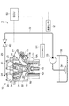
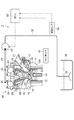
まず、図1を用いて、第1実施形態に係る内燃機関の給油量制御装置1の構成について説明する。図1は、第1実施形態に係る給油量制御装置1の全体構成を示す図である。
(First embodiment)
First, the configuration of an oil supply
エンジン10のシリンダブロック11に形成されたシリンダ12内には、図の上下方向に往復移動可能にピストン13が配置されている。ピストン13は、コンロッド14によって図示していないクランク軸に連結されている。ピストン13の冠面と、動弁系を備えたシリンダヘッド15との間の空間が燃焼室16を形成する。
A
シリンダヘッド15の燃焼室16に面する部位には、インジェクタ17、点火プラグ18、吸気バルブ19及び排気バルブ20が配置されている。インジェクタ17は、ピストン13のキャビティ13Aに向けて燃料を噴射しうる方向に配置されている。また、点火プラグ18は、吸気バルブ19と排気バルブ20との間で、キャビティ13Aのインジェクタ17側とは逆の端近傍に位置するように配置されている。吸気バルブ19は燃焼室16と吸気ポート21との間に配置され、排気バルブ20は燃焼室16と排気ポート22との間に配置される。
An
吸気バルブ19及び排気バルブ20のステムエンド部にはロッカーアーム25,26の一端部が当接されている。ロッカーアーム25,26の他端部には、カム23,24とロッカーアーム25,26とのクリアランスを調節するラッシュアジャスタ27,28が配置されている。また、ロッカーアーム25,26の略中間部には、カム23,24が当接されている。ロッカーアーム25,26の略中間部がカム23,24により押されることにより、ロッカーアーム25,26の上記他端部を支点として、ロッカーアーム25,26が往復揺動される。そして、往復揺動されるロッカーアーム25,26によって吸気バルブ19及び排気バルブ20が開閉駆動される。なお、本実施形態では、ロッカーアーム25,26のカム23,24との接触部分にローラを装着したローラロッカーアームを用いた。
One end portions of
カム23,24が形成されたカムシャフトの上方には、カム23,24及びロッカーアーム25,26に潤滑油を供給する動弁系潤滑油通路29が配置されている。動弁系潤滑油通路29のカム23,24と対応する位置には、潤滑油をカム23,24へ吹き出す潤滑油吹き出し口30,31が設けられており、カムシャフト上部からカム23,24及びロッカーアーム25,26などの潤滑部に潤滑油が供給される。
Above the camshaft in which the
動弁系潤滑油通路29の他端は、カム23,24及びロッカーアーム25,26に供給される潤滑油量を調節する電磁弁40の流出口に接続されている。電磁弁40は、電子制御装置(以下「ECU」という)50に接続されており、ECU50からの駆動信号によって開閉駆動される。すなわち、電磁弁40は調節手段として機能する。なお、オン・オフ式の電磁弁に代えて潤滑油の流量を連続的に調節することができるリニアソレノイドやデューティソレノイドなどの電磁流量制御弁を用いてもよい。
The other end of the valve train lubricating
電磁弁40の流入口には潤滑油通路32の一端が接続されている。潤滑油通路32の他端は、エンジン10により駆動される潤滑油ポンプ33の吐出口に接続されている。オイルパン35に貯留されている潤滑油は、オイルストレーナ34を介して潤滑油ポンプ33によって吸引され、潤滑油通路32を通って電磁弁40に圧送される。なお、エンジン10には、電磁弁40を介してロッカーアーム25,26などに潤滑油を供給する動弁系潤滑油通路29及び潤滑油通路32の他に、電磁弁40を介することなくカムジャーナルなどに潤滑油を供給する潤滑油通路やピストン13やクランクなどに潤滑油を供給する潤滑油通路などが設けられている。図1では簡単のため動弁系潤滑油通路29及び潤滑油通路32のみを示し、他の潤滑油通路を省略した。
One end of the lubricating
ECU50は、演算を行うマイクロプロセッサ、マイクロプロセッサに各処理を実行させるためのプログラム等を記憶するROM、演算結果などの各種データを記憶するRAM等を有して構成されており、エンジン10を総合的に制御すると共に電磁弁40を開閉駆動するものである。すなわち、ECU50は制御手段として機能する。ECU50には、電磁弁40の他に、エンジン10のクランク位置を検出するクランク角センサ51や潤滑油の温度を検出する油温センサ52などが接続されている。また、ECU50は、電磁弁40を駆動する駆動回路を有している。
The
次に、給油量制御装置1の動作について説明する。まず、ECU50では、クランク角センサ51により検出されたクランク位置及び油温センサ52により検出された潤滑油温度Toが読み込まれると共に、クランク位置の変化量からエンジン回転数Neが算出される。
Next, the operation of the oil supply
続いてECU50では、エンジン回転数Ne及び潤滑油温度Toに基づいて、電磁弁40の弁位置(開弁位置又は閉弁位置)が決定される。具体的には、ECU40のROMには、エンジン回転数Neと潤滑油温度Toと電磁弁40の弁位置との関係を定めたマップ(第1電磁弁位置マップ)が記憶されており、エンジン回転数Ne及び潤滑油温度Toに基づいてこの第1電磁弁位置マップが検索されることにより電磁弁40の弁位置が決定される。
Subsequently, the
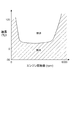
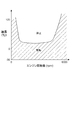
ここで、潤滑油が飛沫になりにくい領域や多量の潤滑油が必要とされる領域など、必要とされる潤滑油量に対して充分な潤滑油飛沫を供給することができない領域では強制潤滑が必要になる。第1電磁弁位置マップは、図2に斜線で示されるように、例えば、低油温領域、低速回転領域、高速回転領域などの強制潤滑が必要とされる領域で電磁弁40が開弁されるように設定されている。
Here, forced lubrication is not possible in areas where it is difficult to supply sufficient amount of splashing oil to the required amount of lubricating oil, such as areas where lubricating oil is difficult to splash or areas where a large amount of lubricating oil is required. I need it. In the first electromagnetic valve position map, as indicated by hatching in FIG. 2, for example, the
一方、ミスト潤滑で必要とされる量の潤滑油を供給することができる領域、例えば、暖機後に中速回転で運転されるような領域では、強制潤滑を停止してミスト潤滑をおこなうべく、電磁弁40が閉弁されるように設定されている。
On the other hand, in a region where the amount of lubricating oil required for mist lubrication can be supplied, for example, in a region where the engine is operated at a medium speed after warm-up, in order to stop forced lubrication and perform mist lubrication, The
そして、決定された弁位置に応じた駆動信号が、ECU50から電磁弁40に対して出力され、電磁弁40が閉弁又は開弁駆動される。一方、エンジン10によって潤滑油ポンプ33が駆動されることにより、オイルパン35に貯留されている潤滑油が潤滑油通路32を通って電磁弁40に圧送される。
Then, a drive signal corresponding to the determined valve position is output from the
電磁弁40のソレノイドコイルに通電されて電磁弁40が開弁された場合、電磁弁40を経て動弁系潤滑油通路29により導かれた潤滑油が、潤滑油吹き出し口30,31からカム23,24及びロッカーアーム25,26などに供給される。
When the
一方、電磁弁40のソレノイドコイルへの通電が停止され、電磁弁40が閉弁された場合、カム23,24及びロッカーアーム25,26などへの潤滑油の供給が停止される。ロッカーアーム25,26などへの強制潤滑が停止されたとき、ロッカーアーム25,26などは、電磁弁40を介することなくカムジャーナルなどに供給された潤滑油の飛沫によってミスト潤滑される。
On the other hand, when the energization of the solenoid coil of the
エンジン10の運転領域において、強制潤滑が必要とされる領域としては、エンジン回転数が低く潤滑油ポンプ33の回転数が低いため低油圧で動弁系への給油量が低下する高油温アイドル領域、常温始動領域やアイドル運転領域、低油温のため潤滑油の粘度が高く、潤滑油が飛沫になりにくい低温始動領域、多量の潤滑油を供給する必要がある暖機前加速領域や暖機前登坂路走行領域、及び、信頼性の観点から多量の潤滑油が要求されるレーシング領域などが挙げられる。
In the operating region of the
本実施形態では、エンジン回転数Ne及び潤滑油温度Toに基づき、強制潤滑が必要とされる領域では電磁弁40が開弁されてロッカーアーム25,26などに直接、潤滑油が供給される。一方、ミスト潤滑で必要とされる量の潤滑油を供給することができる領域では、電磁弁40が閉弁されてロッカーアーム25,26などへの強制潤滑が停止され、ミスト潤滑がおこなわれる。このように、本実施形態によれば、エンジン回転数Ne及び潤滑油温度Toに基づいて動弁系を構成するカム23,24及びロッカーアーム25,26などに供給される潤滑油量が調節されるので、エンジン10の全運転領域において、ロッカーアーム25,26などで必要とされる量の潤滑油を供給することが可能となる。
In this embodiment, based on the engine speed Ne and the lubricating oil temperature To, the
ロッカーアーム式の動弁系では、バルブ直動式のものと比較して、より多くの給油が必要とされる。そのため、潤滑油ポンプの容量が大きくなり駆動仕事が増大するため燃費が悪化する。また、ロッカーアームなどに供給された多量の潤滑油がシリンダヘッドからシリンダブロックへ落ちる際、クランクシャフトなどによって攪拌されることによりフリクションが増加し、エンジン性能が低下する。さらに、潤滑油が攪拌されることにより、潤滑油中の気泡率が上昇し、耐焼付き性能が低下する。本実施形態によれば、ロッカーアーム25,26などに強制潤滑が必要とされる運転領域においてのみ強制潤滑をおこなうことができるので、上記フリクションの増加や油中気泡率の増大などを抑制することが可能となる。
The rocker arm type valve operating system requires more oil supply than the valve direct acting type. As a result, the capacity of the lubricating oil pump increases and the driving work increases, resulting in a deterioration in fuel consumption. Further, when a large amount of lubricating oil supplied to the rocker arm or the like falls from the cylinder head to the cylinder block, the friction is increased by agitation by the crankshaft or the like, and the engine performance is deteriorated. Furthermore, when the lubricating oil is agitated, the bubble ratio in the lubricating oil increases, and the seizure resistance performance decreases. According to the present embodiment, the forced lubrication can be performed only in the operation region where the
(第2実施形態)
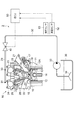
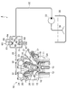
次に、図3を用いて、第2実施形態に係る給油量制御装置2の構成について説明する。図3は、給油量制御装置2の全体構成を示す図である。なお、図3において第1実施形態と同一又は同等の構成要素については同一の符号が付されている。
(Second Embodiment)
Next, the configuration of the oil supply
給油量制御装置2が給油量制御装置1と異なるのは、クランク角センサ51に代えて潤滑油の圧力を検出する油圧センサ53が用いられている点である。油圧センサ53は、ECU50に接続されており、潤滑油の圧力に応じた電気信号をECU50に出力する。油圧センサ53は、油圧検出手段として機能する。その他の構成については、第1実施形態と同一又は同様であるので、ここでは説明を省略する。
The oil supply
次に、給油量制御装置2の動作について説明する。まず、ECU50では、油温センサ52により検出された潤滑油温度To及び油圧センサ53により検出された潤滑油圧力Poが読み込まれる。
Next, the operation of the oil supply
続いてECU50では、潤滑油温度To及び潤滑油圧力Poに基づいて、電磁弁40の弁位置(開弁位置又は閉弁位置)が決定される。具体的には、ECU40のROMには、潤滑油温度Toと潤滑油圧力Poと電磁弁40の弁位置との関係を定めたマップ(第2電磁弁位置マップ)が記憶されており、潤滑油温度To及び潤滑油圧力Poに基づいてこの第2電磁弁位置マップが検索されることにより電磁弁40の弁位置が決定される。
Subsequently, the
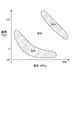
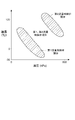
ここで、潤滑油が飛沫になりにくい領域や多量の潤滑油が必要とされる領域など、必要とされる潤滑油量に対して充分な潤滑油飛沫を供給することができない領域では強制潤滑が必要になる。第2電磁弁位置マップは、図4に斜線で示されるように、例えば、低油温領域、低油圧領域、高油温高油圧領域などの強制潤滑が必要とされる領域で電磁弁40が開弁されるように設定されている。
Here, forced lubrication is not possible in areas where it is difficult to supply sufficient amount of splashing oil to the required amount of lubricating oil, such as areas where lubricating oil is difficult to splash or areas where a large amount of lubricating oil is required. I need it. The second electromagnetic valve position map is shown in FIG. 4 as a hatched line, for example, when the
一方、ミスト潤滑で必要とされる量の潤滑油を供給することができる領域、例えば、暖機後に中間油圧で運転されるような領域では、強制潤滑を停止してミスト潤滑をおこなうべく、電磁弁40が閉弁されるように設定されている。
On the other hand, in areas where the amount of lubricating oil required for mist lubrication can be supplied, for example, areas that are operated at intermediate hydraulic pressure after warm-up, electromagnetic lubrication is performed to stop forced lubrication and perform mist lubrication. The
そして、決定された弁位置に応じた駆動信号が、ECU50から電磁弁40に対して出力され、電磁弁40が閉弁又は開弁駆動される。一方、エンジン10によって潤滑油ポンプ33が駆動されることにより、オイルパン35に貯留されている潤滑油が潤滑油通路32を通って電磁弁40に圧送される。
Then, a drive signal corresponding to the determined valve position is output from the
電磁弁40のソレノイドコイルに通電されて電磁弁40が開弁された場合、電磁弁40及び動弁系潤滑油通路29を通過した潤滑油が、潤滑油吹き出し口30,31からカム23,24及びロッカーアーム25,26などに供給される。
When the
一方、電磁弁40のソレノイドコイルへの通電が停止され、電磁弁40が閉弁された場合、カム23,24及びロッカーアーム25,26などへの潤滑油の供給が停止される。ロッカーアーム25,26などへの強制潤滑が停止されたとき、ロッカーアーム25,26などは、電磁弁40を介することなくカムジャーナルなどに供給された潤滑油の飛沫によってミスト潤滑される。
On the other hand, when the energization of the solenoid coil of the
本実施形態では、潤滑油温度To及び潤滑油圧力Poに基づき、強制潤滑が必要とされる領域では電磁弁40が開弁されてロッカーアーム25,26などに直接、潤滑油が供給される。一方、ミスト潤滑で必要とされる量の潤滑油を供給することができる領域では、電磁弁40が閉弁されてロッカーアーム25,26などへの強制潤滑が停止され、ミスト潤滑がおこなわれる。このように、本実施形態によれば、潤滑油温度To及び潤滑油圧力Poに基づいて動弁系を構成するカム23,24及びロッカーアーム25,26などに供給される潤滑油量が調節されるので、エンジン10の全運転領域において、ロッカーアーム25,26などで必要とされる量の潤滑油を供給することが可能となる。
In the present embodiment, based on the lubricating oil temperature To and the lubricating oil pressure Po, the
また、本実施形態によっても、ロッカーアーム25,26などに強制潤滑が必要とされる運転領域においてのみ強制潤滑をおこなうことができるので、フリクションの増加や油中気泡率の増大などを抑制することが可能となる。
Also according to the present embodiment, forced lubrication can be performed only in the operation region where the
(第3実施形態)
次に、図5を用いて、第3実施形態に係る給油量制御装置3の構成について説明する。図5は、給油量制御装置3の全体構成を示す図である。なお、図5において第1実施形態と同一又は同等の構成要素については同一の符号が付されている。
(Third embodiment)
Next, the configuration of the oil supply amount control device 3 according to the third embodiment will be described with reference to FIG. FIG. 5 is a diagram illustrating an overall configuration of the oil supply amount control device 3. In FIG. 5, the same or equivalent components as those in the first embodiment are denoted by the same reference numerals.
給油量制御装置3が給油量制御装置1と異なるのは、ロッカーアーム25,26などへの給油量を調節する手段として、電磁弁40に代えて電動潤滑油ポンプ42が用いられている点、及び、潤滑油通路32に潤滑油ポンプ33が設けられていない点である。電動潤滑油ポンプ42はECU50に接続されており、ECU50からの駆動信号によって制御される。なお、カムジャーナル、ピストン13及びクランクなどに対しては、エンジン10によって駆動される潤滑油ポンプにより潤滑油が圧送される。その他の構成については、第1実施形態と同一又は同様であるので、ここでは説明を省略する。
The oil supply amount control device 3 is different from the oil supply
次に、給油量制御装置3の動作について説明する。まず、ECU50では、クランク角センサ51により検出されたクランク位置及び油温センサ52により検出された潤滑油温度Toが読み込まれると共に、クランク位置の変化量からエンジン回転数Neが算出される。
Next, the operation of the oil supply amount control device 3 will be described. First, the
続いてECU50では、エンジン回転数Ne及び潤滑油温度Toに基づいて、電動潤滑油ポンプ42の作動状態(駆動状態又は停止状態)が決定される。具体的には、ECU40のROMには、エンジン回転数Neと潤滑油温度Toと電動潤滑油ポンプ42の作動状態との関係を定めたマップ(作動状態動マップ)が記憶されており、エンジン回転数Ne及び潤滑油温度Toに基づいてこの作動状態マップが検索されることにより電動潤滑油ポンプ42の作動状態が決定される。
Subsequently, the
ここで、潤滑油が飛沫になりにくい領域や多量の潤滑油が必要とされる領域など、必要とされる潤滑油量に対して充分な潤滑油飛沫を供給することができない領域では強制潤滑が必要になる。作動状態マップは、図6に斜線で示されるように、例えば、低油温領域、低速回転領域、高速回転領域などの強制潤滑が必要とされる領域で電動潤滑油ポンプ42が駆動されるように設定されている。
Here, forced lubrication is not possible in areas where it is difficult to supply sufficient amount of splashing oil to the required amount of lubricating oil, such as areas where lubricating oil is difficult to splash or areas where a large amount of lubricating oil is required. I need it. The operation state map is such that the electric
一方、ミスト潤滑で必要とされる量の潤滑油を供給することができる領域、例えば、暖機後に中速回転で運転されるような領域では、強制潤滑を停止してミスト潤滑をおこなうべく、電動潤滑油ポンプ42が停止されるように設定されている。
On the other hand, in a region where the amount of lubricating oil required for mist lubrication can be supplied, for example, in a region where the engine is operated at a medium speed after warm-up, in order to stop forced lubrication and perform mist lubrication, The electric
そして、決定された作動状態に応じた駆動電力が、ECU50から電動潤滑油ポンプ42に対して出力され、電動潤滑油ポンプ42の駆動又は停止が制御される。
Then, drive power corresponding to the determined operating state is output from the
電動潤滑油ポンプ42が駆動された場合、電動潤滑油ポンプ42から吐出された潤滑油が、動弁系潤滑油通路29に設けられた潤滑油吹き出し口30,31からカム23,24及びロッカーアーム25,26などに供給される。
When the electric
一方、電動潤滑油ポンプ42が停止された場合、カム23,24及びロッカーアーム25,26などへの潤滑油の供給が停止される。ロッカーアーム25,26などへの強制潤滑が停止されたとき、ロッカーアーム25,26などは、エンジン10により駆動される潤滑油ポンプによりカムジャーナルなどに供給された潤滑油の飛沫によってミスト潤滑される。
On the other hand, when the electric
本実施形態では、エンジン回転数Ne及び潤滑油温度Toに基づき、強制潤滑が必要とされる領域では電動潤滑油ポンプ42が駆動されてロッカーアーム25,26などに直接、潤滑油が供給される。一方、ミスト潤滑で必要とされる量の潤滑油を供給することができる領域では、電動潤滑油ポンプ42が停止されてロッカーアーム25,26などへの強制潤滑が停止され、ミスト潤滑がおこなわれる。このように、本実施形態によれば、エンジン回転数Ne及び潤滑油温度Toに基づいて動弁系を構成するカム23,24及びロッカーアーム25,26などに供給される潤滑油量が調節されるので、エンジン10の全運転領域において、ロッカーアーム25,26などで必要とされる量の潤滑油を供給することが可能となる。
In the present embodiment, based on the engine speed Ne and the lubricating oil temperature To, the electric
また、本実施形態によっても、ロッカーアーム25,26などに強制潤滑が必要とされる運転領域においてのみ強制潤滑をおこなうことができるので、フリクションの増加や油中気泡率の増大などを抑制することが可能となる。
Also according to the present embodiment, forced lubrication can be performed only in the operation region where the
なお、本実施形態では電動潤滑油ポンプ42を駆動又は停止することによって、ロッカーアーム25,26などへの給油量を調節したが、電動潤滑油ポンプ42の回転数を制御することによって、給油量を連続的に調節するようにしてもよい。また、本実施形態では、エンジン回転数Ne及び潤滑油温度Toに基づいて電動潤滑油ポンプ42の作動状態を決定したが、潤滑油温度To及び潤滑油圧力Poに基づいて電動潤滑油ポンプ42の作動状態を決定するようにしてもよい。
In this embodiment, the amount of oil supplied to the
(第4実施形態)
次に、図7を用いて、第4実施形態に係る給油量制御装置4の構成について説明する。図7は、給油量制御装置4の全体構成を示す図である。なお、図7において第1実施形態と同一又は同等の構成要素については同一の符号が付されている。
(Fourth embodiment)
Next, the configuration of the oil supply
給油量制御装置4は、ロッカーアーム25,26などへの給油量を調節する手段として、電磁弁40に代えて第1流量制御弁60及び第2流量制御弁66が用いられている点、及び、ECU50に電磁弁40を駆動する機能が備えられていない点で給油量制御装置1と異なる。その他の構成については、第1実施形態と同一又は同様であるので、ここでは説明を省略する。
The oil supply
第1流量制御弁60と第2流量制御弁66は、並列に潤滑油通路32に介装されている。第1及び第2流量制御弁60,66は、円周方向に凹部を有する円筒状のバルブ62,68がバルブハウジング61,67に対して軸方向(図面の上下方向)に相対変位して流路断面積が変化することにより、通過する潤滑油の流量を調節するものである。第1及び第2流量制御弁60,66は、バルブ62,68を初期位置に付勢する第1,第2スプリング63,69と、第1及び第2通路64,70により導かれた潤滑油の圧力によってバルブ62,68を第1,第2スプリング63,69に抗して駆動する油圧室65,71とを備える。油圧室65,71はバルブ62,68の上面とバルブハウジング61,67との間に画成され、第1、第2通路64,70によって潤滑油通路32と連通している。
The first
油圧室65,71に油圧がかかっていない状態では、バルブ62,68が初期位置にあり、潤滑油の流路を遮断している。油圧室65,71に導入される潤滑油の圧力が上昇した場合には、バルブ62,68が第1、第2スプリング63,69に抗して駆動され、バルブ62,68の凹部により潤滑油の流路が形成される。油圧室65,71に導入される潤滑油の圧力がさらに上昇した場合、バルブ62,68が図面下方にさらに駆動され、再び潤滑油の流路が遮断される。
In a state where no hydraulic pressure is applied to the
スプリング63,69は、バルブ62,68の下面とバルブハウジング61,67の底面との間に介装されている。第1,第2スプリング63,69は形状記憶合金などで形成され、潤滑油温度が上昇するのに伴って第1,第2スプリング63,69の付勢力が弱くなるようになっている。したがって、潤滑油温度が低い場合には、第1,第2スプリング63,69の付勢力が強いため、潤滑油温度が高い場合と比較して、第1,第2流量制御弁60,66を開弁させるために必要な潤滑油圧力がより高くなる。また、潤滑油温度が上昇するに伴って、第1,第2スプリング63,69の付勢力が弱くなるため、第1,第2流量制御弁60,66を開弁させるために必要な潤滑油圧力が低下する。
The
また、同一温度では、第1スプリング63の付勢力は第2スプリング69の付勢力より弱く設定されている。したがって、同一の潤滑油温度において、第1流量制御弁60は、第2流量制御弁と比較してより低い潤滑油圧力で開弁する。このようにして、第1,第2流量制御弁60,66のバルブ62,68が潤滑油温度及び潤滑油圧力に応じて駆動され、ロッカーアーム25,26などに供給される潤滑油の量が調節される。本実施形態では、バルブ62,68が調節手段として機能し、油圧室65,71及び第1,第2スプリング63,69が制御手段として機能する。
At the same temperature, the urging force of the first spring 63 is set to be weaker than the urging force of the
上述したように第1スプリング63及び第2スプリング69の付勢力が設定されているので、図8に示されるように、第1流量制御弁60は、第2流量制御弁66と比較して、低油温側及び低油圧側で開弁する。逆に、第2流量制御弁66は、第1流量制御弁66と比較して、高油温高油圧側で開弁する。したがって、第1流量制御弁60と第2流量制御弁66とを組み合わせることにより、例えば、低油温領域、低油圧領域、高油温高油圧領域などの強制潤滑が必要とされる領域で第1流量制御弁60又は/及び第2流量制御弁66が開弁され、潤滑油吹き出し口30,31からカム23,24及びロッカーアーム25,26などに潤滑油が供給される。
Since the urging force of the first spring 63 and the
一方、ミスト潤滑で必要とされる量の潤滑油を供給することができる領域、例えば、暖機後に中間油圧で運転されるような領域では、第1流量制御弁60及び第2流量制御弁66が閉弁されて強制潤滑が停止される。ロッカーアーム25,26などへの強制潤滑が停止されたとき、ロッカーアーム25,26などは、第1,第2流量制御弁60,66を介することなくカムジャーナルなどに供給された潤滑油の飛沫によってミスト潤滑される。
On the other hand, in a region where the amount of lubricating oil required for mist lubrication can be supplied, for example, in a region where the intermediate oil pressure is operated after warm-up, the first
本実施形態では、潤滑油温度及び潤滑油圧力に基づき、強制潤滑が必要とされる領域では第1流量制御弁60又は/及び第2流量制御弁66が開弁されてロッカーアーム25,26などに直接、潤滑油が供給される。一方、ミスト潤滑で必要とされる量の潤滑油を供給することができる領域では、第1流量制御弁60及び第2流量制御弁66が閉弁されてロッカーアーム25,26などへの強制潤滑が停止され、ミスト潤滑がおこなわれる。このように、本実施形態によれば、潤滑油温度及び潤滑油圧力に基づいて動弁系を構成するカム23,24及びロッカーアーム25,26などに供給される潤滑油量が調節されるので、エンジン10の全運転領域において、ロッカーアーム25,26などで必要とされる量の潤滑油を供給することが可能となる。
In the present embodiment, the first flow
また、本実施形態によっても、ロッカーアーム25,26などに強制潤滑が必要とされる運転領域においてのみ強制潤滑をおこなうことができるので、フリクションの増加や油中気泡率の増大などを抑制することが可能となる。
Also according to the present embodiment, forced lubrication can be performed only in the operation region where the
1,2,3,4…給油量制御装置、10…エンジン、19…吸気バルブ、20…排気バルブ、23,24…カム、25,26…ロッカーアーム、29…動弁系潤滑油通路、32…潤滑油通路、33…潤滑油ポンプ、34…オイルストレーナ、40…電磁弁、42…電動潤滑油ポンプ、50…ECU、51…クランク角センサ、52…油温センサ、53…油圧センサ、60…第1流量制御弁、66…第2流量制御弁。 1, 2, 3, 4,... Oil supply amount control device, 10, engine, 19, intake valve, 20, exhaust valve, 23, 24, cam, 25, 26, rocker arm, 29, valve system lubricating oil passage, 32 DESCRIPTION OF SYMBOLS ... Lubricating oil path, 33 ... Lubricating oil pump, 34 ... Oil strainer, 40 ... Solenoid valve, 42 ... Electric lubricating oil pump, 50 ... ECU, 51 ... Crank angle sensor, 52 ... Oil temperature sensor, 53 ... Hydraulic pressure sensor, 60 ... 1st flow control valve, 66 ... 2nd flow control valve.
Claims (4)
前記潤滑油通路に設けられ、前記動弁系に供給される潤滑油の給油量を調節する調節手段と、
前記内燃機関の運転状態に応じて、前記調節手段を制御する制御手段と、を備える、ことを特徴とする内燃機関の給油量制御装置。 A lubricating oil passage for supplying lubricating oil to the valve train of the internal combustion engine;
An adjusting means provided in the lubricating oil passage for adjusting the amount of lubricating oil supplied to the valve train;
And a control means for controlling the adjusting means in accordance with an operating state of the internal combustion engine.
前記内燃機関の機関回転数を検出する回転数検出手段と、を備え、
前記制御手段は、前記温度検出手段により検出された潤滑油温度及び前記回転数検出手段により検出された機関回転数に基づいて、前記調節手段を制御する、ことを特徴とする請求項1に記載の内燃機関の給油量制御装置。 Temperature detecting means for detecting the temperature of the lubricating oil;
A rotational speed detection means for detecting the engine rotational speed of the internal combustion engine,
2. The control unit according to claim 1, wherein the control unit controls the adjustment unit based on a lubricating oil temperature detected by the temperature detection unit and an engine speed detected by the rotation number detection unit. Oil quantity control device for internal combustion engine.
前記潤滑油の圧力を検出する圧力検出手段と、を備え、
前記制御手段は、前記温度検出手段により検出された潤滑油温度及び前記圧力検出手段により検出された潤滑油圧力に基づいて、前記調節手段を制御する、ことを特徴とする請求項1に記載の内燃機関の給油量制御装置。 Temperature detecting means for detecting the temperature of the lubricating oil;
Pressure detecting means for detecting the pressure of the lubricating oil,
The said control means controls the said adjustment means based on the lubricating oil temperature detected by the said temperature detection means, and the lubricating oil pressure detected by the said pressure detection means, The control means of Claim 1 characterized by the above-mentioned. An oil quantity control device for an internal combustion engine.
前記潤滑油通路は、潤滑油を前記ロッカーアームに供給し、
前記調節手段は、前記ロッカーアームに供給される潤滑油の給油量を調節する、ことを特徴とする請求項1〜3のいずれか1項に記載の内燃機関の給油量制御装置。 The valve system has a rocker arm,
The lubricating oil passage supplies lubricating oil to the rocker arm,
The oil supply amount control device for an internal combustion engine according to any one of claims 1 to 3, wherein the adjusting means adjusts an oil supply amount of the lubricating oil supplied to the rocker arm.
Priority Applications (1)
| Application Number | Priority Date | Filing Date | Title |
|---|---|---|---|
| JP2004111415A JP2005291183A (en) | 2004-04-05 | 2004-04-05 | Oil quantity control device for internal combustion engine |
Applications Claiming Priority (1)
| Application Number | Priority Date | Filing Date | Title |
|---|---|---|---|
| JP2004111415A JP2005291183A (en) | 2004-04-05 | 2004-04-05 | Oil quantity control device for internal combustion engine |
Publications (1)
| Publication Number | Publication Date |
|---|---|
| JP2005291183A true JP2005291183A (en) | 2005-10-20 |
Family
ID=35324380
Family Applications (1)
| Application Number | Title | Priority Date | Filing Date |
|---|---|---|---|
| JP2004111415A Pending JP2005291183A (en) | 2004-04-05 | 2004-04-05 | Oil quantity control device for internal combustion engine |
Country Status (1)
| Country | Link |
|---|---|
| JP (1) | JP2005291183A (en) |
Cited By (3)
| Publication number | Priority date | Publication date | Assignee | Title |
|---|---|---|---|---|
| JP2016098750A (en) * | 2014-11-25 | 2016-05-30 | スズキ株式会社 | Oil passage structure of internal combustion engine |
| JP2017190734A (en) * | 2016-04-14 | 2017-10-19 | 株式会社豊田自動織機 | Oil supply device and oil supply method for internal combustion engine |
| JP2020007970A (en) * | 2018-07-09 | 2020-01-16 | 株式会社豊田自動織機 | Internal combustion engine |
-
2004
- 2004-04-05 JP JP2004111415A patent/JP2005291183A/en active Pending
Cited By (3)
| Publication number | Priority date | Publication date | Assignee | Title |
|---|---|---|---|---|
| JP2016098750A (en) * | 2014-11-25 | 2016-05-30 | スズキ株式会社 | Oil passage structure of internal combustion engine |
| JP2017190734A (en) * | 2016-04-14 | 2017-10-19 | 株式会社豊田自動織機 | Oil supply device and oil supply method for internal combustion engine |
| JP2020007970A (en) * | 2018-07-09 | 2020-01-16 | 株式会社豊田自動織機 | Internal combustion engine |
Similar Documents
| Publication | Publication Date | Title |
|---|---|---|
| JP6308251B2 (en) | Engine oil supply device | |
| JP6187416B2 (en) | Engine oil supply device | |
| JP6278049B2 (en) | Engine oil supply device | |
| JP2008286063A (en) | Lubricating device for internal combustion engine | |
| US9828900B2 (en) | Oil jet apparatus of internal combustion engine | |
| JP6094545B2 (en) | Engine oil supply device | |
| US20070221149A1 (en) | Auxiliary cam phaser hydraulic circuit and method of operation | |
| JPH09209733A (en) | Engine piston lubricator | |
| JP4019844B2 (en) | Lubricating device for internal combustion engine | |
| JP2005291183A (en) | Oil quantity control device for internal combustion engine | |
| JP5569456B2 (en) | Internal combustion engine with lash adjuster | |
| JP2002295219A (en) | Engine lubrication equipment | |
| JP5531762B2 (en) | Engine oiling device | |
| KR20180056230A (en) | Oil supply apparatus for turbo charger and method for controlling the same | |
| JP6631590B2 (en) | Oil circulation device for internal combustion engine | |
| JP6350567B2 (en) | Engine oil supply device | |
| JP2016223290A (en) | Lubrication device of engine | |
| JP2004340066A (en) | Internal combustion engine | |
| US8418671B2 (en) | Magnetorheological lubrication of an internal combustion engine | |
| JP2012219689A (en) | Valve gear for internal combustion engine | |
| JP2018159339A (en) | Control device of engine | |
| JP4337620B2 (en) | Variable valve mechanism for internal combustion engine | |
| JP6583112B2 (en) | Oil supply device and oil supply method for internal combustion engine | |
| JP2007170354A (en) | Oil supply device for internal combustion engine | |
| KR20030027404A (en) | Approvement fuel efficiency of engine in vehicle and control method thereof |
Legal Events
| Date | Code | Title | Description |
|---|---|---|---|
| A621 | Written request for application examination |
Free format text: JAPANESE INTERMEDIATE CODE: A621 Effective date: 20070312 |
|
| A131 | Notification of reasons for refusal |
Effective date: 20090908 Free format text: JAPANESE INTERMEDIATE CODE: A131 |
|
| A02 | Decision of refusal |
Free format text: JAPANESE INTERMEDIATE CODE: A02 Effective date: 20100105 |