JP2005291101A - Engine air-fuel ratio control device - Google Patents
Engine air-fuel ratio control device Download PDFInfo
- Publication number
- JP2005291101A JP2005291101A JP2004108095A JP2004108095A JP2005291101A JP 2005291101 A JP2005291101 A JP 2005291101A JP 2004108095 A JP2004108095 A JP 2004108095A JP 2004108095 A JP2004108095 A JP 2004108095A JP 2005291101 A JP2005291101 A JP 2005291101A
- Authority
- JP
- Japan
- Prior art keywords
- fuel ratio
- air
- value
- sub
- feedback
- Prior art date
- Legal status (The legal status is an assumption and is not a legal conclusion. Google has not performed a legal analysis and makes no representation as to the accuracy of the status listed.)
- Granted
Links
Images


Classifications
-
- Y—GENERAL TAGGING OF NEW TECHNOLOGICAL DEVELOPMENTS; GENERAL TAGGING OF CROSS-SECTIONAL TECHNOLOGIES SPANNING OVER SEVERAL SECTIONS OF THE IPC; TECHNICAL SUBJECTS COVERED BY FORMER USPC CROSS-REFERENCE ART COLLECTIONS [XRACs] AND DIGESTS
- Y02—TECHNOLOGIES OR APPLICATIONS FOR MITIGATION OR ADAPTATION AGAINST CLIMATE CHANGE
- Y02T—CLIMATE CHANGE MITIGATION TECHNOLOGIES RELATED TO TRANSPORTATION
- Y02T10/00—Road transport of goods or passengers
- Y02T10/10—Internal combustion engine [ICE] based vehicles
- Y02T10/40—Engine management systems
Landscapes
- Electrical Control Of Air Or Fuel Supplied To Internal-Combustion Engine (AREA)
- Combined Controls Of Internal Combustion Engines (AREA)
Abstract
【課題】フロントA/Fセンサが故障しても、空燃比フィードバック制御性を悪化させることなく、良好な空燃比フィードバックの応答性を得ることができるようにする。
【解決手段】触媒8の上流に配設したフロントA/Fセンサ10で検出した空燃比に基づいてメインフィードバック制御を行うと共に、触媒8の下流に配設したリヤO2センサ11で検出した空燃比に基づき目標空燃比を補正するサブフィードバック制御を行う。サブフィードバック補正値αO2はガード値により制御量が制限されており、サブフィードバック平均値αO2avが、ガード値の一方に貼り付き傾向にあるときは、ガード中心値Sgdoを移動させて(S67,S38)、貼り付き傾向を解消する。このときガード中心値Sgdoの移動量が大きい場合は、フロントA/Fセンサ10の故障と判定する。
【選択図】図7
Even if a front A / F sensor fails, it is possible to obtain good air-fuel ratio feedback responsiveness without deteriorating air-fuel ratio feedback controllability.
A main feedback control is performed based on an air-fuel ratio detected by a front A / F sensor disposed upstream of a catalyst, and an air-fuel ratio detected by a rear O2 sensor disposed downstream of the catalyst. Sub-feedback control for correcting the target air-fuel ratio is performed based on this. The control amount of the sub feedback correction value αO2 is limited by the guard value. When the sub feedback average value αO2av tends to stick to one of the guard values, the guard center value Sgdo is moved (S67, S38). , Eliminate the sticking tendency. At this time, if the movement amount of the guard center value Sgdo is large, it is determined that the front A / F sensor 10 has failed.
[Selection] Figure 7
Description
本発明は、触媒の上流と下流に空燃比検出手段を配設し、両空燃比検出手段で検出した空燃比に基づいて空燃比フィードバック制御を行うと共に、フロント空燃比検出手段の故障診断を行うエンジンの空燃比制御装置に関する。 In the present invention, air-fuel ratio detection means are provided upstream and downstream of the catalyst, air-fuel ratio feedback control is performed based on the air-fuel ratio detected by both air-fuel ratio detection means, and failure diagnosis of the front air-fuel ratio detection means is performed. The present invention relates to an air-fuel ratio control device for an engine.
近年、自動車のエンジン制御システムでは、排気系の中途に介装した三元触媒の排気ガス浄化率を高めるために、触媒の上流側と下流側とに空燃比センサを各々配設した、いわゆる2センサ空燃比制御システムが知られている。この2センサ空燃比制御システムとして、触媒上流側に、排気ガス中の空燃比を、この空燃比に比例した値で検出する空燃比センサ(以下「フロントA/Fセンサ」と称する)を配設し、又、触媒下流側に、排気ガス中の空燃比をリッチ/リーンで検出する酸素センサ(以下「リヤO2センサ」と称する)を配設するものがある。 2. Description of the Related Art Recently, in an automobile engine control system, in order to increase the exhaust gas purification rate of a three-way catalyst interposed in the middle of an exhaust system, air-fuel ratio sensors are respectively provided on the upstream side and the downstream side of the catalyst. Sensor air-fuel ratio control systems are known. As the two-sensor air-fuel ratio control system, an air-fuel ratio sensor (hereinafter referred to as “front A / F sensor”) that detects the air-fuel ratio in the exhaust gas with a value proportional to the air-fuel ratio is disposed upstream of the catalyst. In addition, there is an oxygen sensor (hereinafter referred to as “rear O2 sensor”) that detects the air-fuel ratio in the exhaust gas in a rich / lean manner on the downstream side of the catalyst.
このような2センサ空燃比制御システムでは、触媒に流入する排気ガスの空燃比をフロントA/Fセンサで検出し、検出した空燃比を上流側目標空燃比(例えば、理論空燃比(λ=1.0))に収束させるように空燃比フィードバック制御(メインフィードバック制御)を行うと共に、触媒を通過した排気ガスの空燃比リッチ或いは空燃比リーンをリヤO2センサで検出して、下流側の空燃比が下流側目標空燃比に収束するように上流側目標空燃比を補正するフィードバック制御(サブフィードバック制御)を行うようにしている。 In such a two-sensor air-fuel ratio control system, the air-fuel ratio of the exhaust gas flowing into the catalyst is detected by the front A / F sensor, and the detected air-fuel ratio is detected as the upstream target air-fuel ratio (for example, the theoretical air-fuel ratio (λ = 1.0 )), The air-fuel ratio feedback control (main feedback control) is performed so that the air-fuel ratio rich or air-fuel ratio lean of the exhaust gas that has passed through the catalyst is detected by the rear O2 sensor, and the downstream air-fuel ratio is reduced downstream. Feedback control (sub-feedback control) for correcting the upstream target air-fuel ratio so as to converge to the side target air-fuel ratio is performed.
この場合、上流側目標空燃比が理論空燃比付近からずれた状態が継続されると、サブフィードバック制御により上流側目標空燃比が過剰に補正されてしまい空燃比制御性が却って阻害される。そのため、例えば、特許文献1(特開2001−304018号公報)に開示されているように、サブフィードバック補正値を制限するガード値を設定し、サブフィードバック補正値がガード値に達したときは、サブフィードバック補正値をガード値で制限することで、上流側目標空燃比の過補正を防止する技術が知られている。 In this case, if the state in which the upstream target air-fuel ratio deviates from the vicinity of the theoretical air-fuel ratio is continued, the upstream target air-fuel ratio is excessively corrected by the sub-feedback control, and the air-fuel ratio controllability is hindered. Therefore, for example, as disclosed in Patent Document 1 (Japanese Patent Application Laid-Open No. 2001-304018), when a guard value for limiting the sub feedback correction value is set and the sub feedback correction value reaches the guard value, There is known a technique for preventing overcorrection of the upstream target air-fuel ratio by limiting the sub-feedback correction value with a guard value.
ところで、フロントA/Fセンサの劣化或いは故障により、フロントA/Fセンサで検出した空燃比と実際の空燃比とにずれが生じた場合、例えば、フロントA/Fセンサでは空燃比を、λ=1.0と検出したが、実際の空燃比はλ=1.1である場合、リヤO2センサで検出する空燃比はリーンとなる。従って、サブフィードバック制御では、上流側目標空燃比をリッチ補正して、下流側目標空燃比が理論空燃比となるように制御するが、サブフィードバック補正値がガード値に達した場合、サブフィードバック補正値は一定値となり、それ以上のサブフィードバック制御が困難となる。 By the way, when there is a difference between the air-fuel ratio detected by the front A / F sensor and the actual air-fuel ratio due to deterioration or failure of the front A / F sensor, for example, the air-fuel ratio in the front A / F sensor is set to λ = When 1.0 is detected but the actual air-fuel ratio is λ = 1.1, the air-fuel ratio detected by the rear O2 sensor becomes lean. Therefore, in the sub-feedback control, the upstream target air-fuel ratio is richly corrected so that the downstream target air-fuel ratio becomes the stoichiometric air-fuel ratio, but when the sub-feedback correction value reaches the guard value, the sub-feedback correction The value becomes a constant value, and further sub-feedback control becomes difficult.
そのため、サブフィードバック補正量の貼り付きが、一時的な空燃比の変動によるものか、或いはフロントA/Fセンサの故障に起因するものかを判別する技術が必要となる。フロントA/Fセンサの故障を診断するものとして、サブフィードバック補正値のガード値に対する貼り付き時間を計時し、所定時間以上連続して貼り付いているとき、フロントA/Fセンサの故障と診断する技術が知られている。
しかし、サブフィードバック補正値のガード値はエンジン負荷によって変動し、又、サブフィードバック補正値も負荷変動の影響を受けて大きく変動し易いため、エンジン負荷変動中は、フロントA/Fセンサが故障しているにも拘わらず、サブフィードバック補正値がガード値内に収まる場合があり、フロントA/Fセンサの故障を正確に検出することができない不都合がある。 However, the guard value of the sub-feedback correction value varies depending on the engine load, and the sub-feedback correction value is likely to fluctuate greatly due to the influence of the load variation. Therefore, the front A / F sensor breaks down during engine load variation. Nevertheless, the sub-feedback correction value may fall within the guard value, and there is a disadvantage that a failure of the front A / F sensor cannot be detected accurately.
一方、フロントA/Fセンサが正常であっても、例えば新品の触媒では、リヤO2センサの出力波形が、フロントA/Fセンサの故障時の波形と近似する運転条件が存在する。このような運転状態で、フロントA/Fセンサの故障診断を実行すると、誤診断が生じ易く、診断精度に問題が出てくる。 On the other hand, even if the front A / F sensor is normal, for example, with a new catalyst, there are operating conditions in which the output waveform of the rear O2 sensor approximates the waveform at the time of the failure of the front A / F sensor. If a failure diagnosis of the front A / F sensor is executed in such an operating state, a misdiagnosis is likely to occur and a problem arises in the diagnosis accuracy.
従って、従来の故障診断では、誤診断を防止するため、エンジンの負荷変動が少なく、且つ新品の触媒であってもフロントA/Fセンサの故障を誤診断しない運転領域、すなわち限定された運転領域でのみ故障診断を行っていた。そのため、故障診断の機会が少なく、フロントA/Fセンサの故障を瞬時に検出することができない不都合がある。 Therefore, in the conventional failure diagnosis, in order to prevent misdiagnosis, the operation range in which the engine load fluctuation is small and the front A / F sensor failure is not misdiagnosed even with a new catalyst, that is, the limited operation region. The fault diagnosis was done only with. For this reason, there are few opportunities for failure diagnosis, and there is a disadvantage that a failure of the front A / F sensor cannot be detected instantaneously.
又、フロントA/Fセンサに故障が発生した場合、適正な空燃比制御を続行することが困難となり、空燃比制御性が悪化してしまう。 In addition, when a failure occurs in the front A / F sensor, it is difficult to continue appropriate air-fuel ratio control, and air-fuel ratio controllability is deteriorated.
この対策として、フロントA/Fセンサに故障が生じた場合は、フロントA/Fセンサの出力値に基づくメインフィードバック制御を中止し、リヤO2センサの出力値に基づくサブフィードバック制御にて空燃比フィードバック制御を実行する技術が知られている。 As a countermeasure, when a failure occurs in the front A / F sensor, the main feedback control based on the output value of the front A / F sensor is stopped, and the air-fuel ratio feedback is performed by the sub feedback control based on the output value of the rear O2 sensor. Techniques for performing control are known.
しかし、メインフィードバック制御を中止して、サブフィードバック制御のみで空燃比制御を行った場合、触媒上流の空燃比が空燃比フィードバック制御に全く反映されなくなるため、空燃比フィードバックの応答性が悪くなる問題がある。 However, when the main feedback control is stopped and the air-fuel ratio control is performed only by the sub-feedback control, the air-fuel ratio upstream of the catalyst is not reflected in the air-fuel ratio feedback control at all. There is.
本発明は、上記事情に鑑み、フロントA/Fセンサの故障診断の機会を必要以上に制限することなく、高精度にフロンA/Fセンサの故障を検出することができ、しかも、フロントA/Fセンサが故障した場合であっても、空燃比フィードバック制御性を悪化させることなく、良好なフィードバック応答性を得ることのできるエンジンの空燃比制御装置を提供することを目的とする。 In view of the above circumstances, the present invention can detect a failure of the front A / F sensor with high accuracy without limiting the opportunity for failure diagnosis of the front A / F sensor more than necessary, and the front A / F sensor. An object of the present invention is to provide an air-fuel ratio control device for an engine that can obtain a good feedback response without deteriorating the air-fuel ratio feedback controllability even when the F sensor fails.
上記目的を達成するため本発明は、触媒の上流に配設して、該触媒に流入する排気ガスから空燃比を検出するフロント空燃比検出手段と、上記触媒の下流に配設して、該触媒から排出される排気ガスから空燃比を検出するリヤ空燃比検出手段と、上記フロント空燃比検出手段で検出した触媒上流の空燃比に基づいて排気ガス中の空燃比を目標空燃比に収束させる空燃比フィードバック補正値を設定するメインフィードバック制御手段と、上記リヤ空燃比検出手段で検出した触媒下流の空燃比に基づいて上記目標空燃比を補正するサブフィードバック補正値を設定するサブフィードバック制御手段と、上記サブフィードバック補正値を制限するガード値を有するガード手段とを備えるエンジンの空燃比制御装置において、上記ガード手段は、該ガード値の移動量を、少なくとも上記リヤ空燃比検出手段で検出した空燃比のリッチ時間とリーン時間との時間比と、上記サブフィードバック補正値に応じて設定された設定値とに基づいて設定することを特徴とする。 In order to achieve the above object, the present invention provides a front air-fuel ratio detecting means that is disposed upstream of a catalyst and detects an air-fuel ratio from exhaust gas flowing into the catalyst, and is disposed downstream of the catalyst. Based on the rear air-fuel ratio detection means for detecting the air-fuel ratio from the exhaust gas discharged from the catalyst and the air-fuel ratio upstream of the catalyst detected by the front air-fuel ratio detection means, the air-fuel ratio in the exhaust gas is converged to the target air-fuel ratio. Main feedback control means for setting an air-fuel ratio feedback correction value; sub-feedback control means for setting a sub-feedback correction value for correcting the target air-fuel ratio based on the air-fuel ratio downstream of the catalyst detected by the rear air-fuel ratio detection means; And an air-fuel ratio control apparatus for an engine comprising a guard means having a guard value for limiting the sub-feedback correction value. The amount of movement of the mode value is set based on at least the time ratio between the rich time and the lean time of the air / fuel ratio detected by the rear air / fuel ratio detecting means and the set value set according to the sub feedback correction value. It is characterized by doing.
本発明によれば、フロント空燃比検出手段が故障した場合であっても、空燃比フィードバック制御性を悪化させることなく、良好な空燃比フィードバックの応答性を得ることができる。 According to the present invention, even when the front air-fuel ratio detecting means is out of order, good air-fuel ratio feedback responsiveness can be obtained without deteriorating the air-fuel ratio feedback controllability.
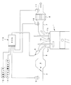
以下、図面に基づいて本発明の一形態を説明する。図1に空燃比制御システムの概略構成図を示す。 Hereinafter, an embodiment of the present invention will be described with reference to the drawings. FIG. 1 shows a schematic configuration diagram of an air-fuel ratio control system.
同図の符号1はエンジンで、エンジン1の吸気ポート1aに吸気マニホルド2を介して吸気通路3が連通され、この吸気通路3の最上流側にエアクリーナ(図示せず)が設けられている。又、吸気通路3の中途にスロットル弁4が介装され、このスロットル弁4の下流側に、吸気マニホルド2の集合部を接続するエアチャンバ5が形成されている。更に、吸気マニホルド2に、噴射方向を吸気ポート1a側に指向するインジェクタ6が固設されている。一方、エンジン1の排気ポート1bに排気通路7が連通され、この排気通路7の中途に触媒8が介装されている。尚、排気通路7の最下流にはマフラ(図示せず)が接続されている。
又、吸気通路3の上流側に吸入空気量センサ9が臨まされている。一方、排気通路7に配設されている触媒8の上流側に、排ガス中の空燃比に比例した電圧を出力する、フロント空燃比検出手段としてのフロント空燃比(A/F)センサ10が配設され、又、触媒8の下流側に、触媒8から排出される排気ガス中の空燃比のリッチ/リーンを検出して電圧値を反転させる、リヤ空燃比検出手段としてのリヤO2センサ11が配設されている。尚、符号12は点火プラグである。
An intake air amount sensor 9 is exposed on the upstream side of the
符号20はマイクロコンピュータ等からなる電子制御装置(ECU)で、吸入空気量センサ9、フロントA/Fセンサ10、リヤO2センサ11、冷却水温からエンジン温度を間接的に検出する水温センサ13、アクセルペダル(図示せず)の踏込み角度を検出するアクセル開度センサ14等の各センサ・スイッチ類から出力される情報に基づき空燃比制御、点火時期制御等の各種制御を行なうと共に、所定運転領域においてフロントA/Fセンサ10の故障診断を行う。
Reference numeral 20 denotes an electronic control unit (ECU) comprising a microcomputer or the like, an intake air amount sensor 9, a front A /
空燃比制御として、本形態は、フロントA/Fセンサ10で検出した空燃比FA/Fに基づいてメインフィードバック制御を実行し、又、リヤO2センサ11で検出した空燃比に基づいてサブフィードバック制御を行う、いわゆる2センサ空燃比制御システムを採用している。
As the air-fuel ratio control, in this embodiment, main feedback control is executed based on the air-fuel ratio FA / F detected by the front A /
本形態によるメインフィードバック制御手段では、フロントA/Fセンサ10で触媒8に流入する排気ガスの空燃比(上流側空燃比)FA/Fを検出し、この上流側空燃比FA/Fが目標空燃比λTgに収束するような空燃比フィードバック補正値αA/Fを設定し、この空燃比フィードバック補正値αA/Fに基づいて燃料噴射量をフィードバック制御する。
In the main feedback control means according to this embodiment, the front A /
一方、サブフィードバック制御手段では、リヤO2センサ11の出力値VO2が、リヤO2センサ11の目標値VOTg(理論空燃比付近の値)に収束させるサブフィードバック補正値αO2を設定し、このサブフィードバック補正値αO2に基づいて、目標空燃比λTgを補正制御する。
On the other hand, the sub-feedback control means sets a sub-feedback correction value αO2 for converging the output value VO2 of the
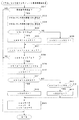
ECU20で実行される空燃比制御は、具体的には図2〜図7に示すフローチャートに従って処理される。 Specifically, the air-fuel ratio control executed by the ECU 20 is processed according to the flowcharts shown in FIGS.
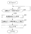
イグニッションスイッチ(図示せず)がONされると、先ず、図2に示す空燃比フィードバック制御ルーチンが実行される。このルーチンでは、先ず、ステップS1で、空燃比フィードバック条件が成立しているか否かを調べる。空燃比フィードバック条件としては、例えば、水温センサ13で検出した冷却水温、及びアクセル開度センサ14で検出したアクセル開度の変化量に基づいて判断する。そして、冷却水温が所定値以上で、且つアクセル開度の変化量が所定値以下のとき(すなわち過渡運転状態にないとき)、空燃比フィードバック条件成立と判定する。
When an ignition switch (not shown) is turned on, first, an air-fuel ratio feedback control routine shown in FIG. 2 is executed. In this routine, first, in step S1, it is checked whether or not an air-fuel ratio feedback condition is satisfied. The air-fuel ratio feedback condition is determined based on, for example, the cooling water temperature detected by the
そして、空燃比フィードバック条件不成立のときは、成立するまで待機し、成立したとき、ステップS2へ進む。ステップS2では目標空燃比λTgを設定する。この目標空燃比λTgは、図3に示す目標空燃比設定ルーチンにて設定される。尚、目標空燃比設定ルーチンについては後述する。 When the air-fuel ratio feedback condition is not satisfied, the process waits until it is satisfied, and when it is satisfied, the process proceeds to step S2. In step S2, a target air-fuel ratio λTg is set. This target air-fuel ratio λTg is set by a target air-fuel ratio setting routine shown in FIG. The target air-fuel ratio setting routine will be described later.
その後、ステップS3へ進み、空燃比フィードバック補正値αA/Fを設定する。この空燃比フィードバック補正値αA/Fは、図4に示す空燃比フィードバック補正値設定ルーチンに従って設定される。尚、空燃比フィードバック補正値設定ルーチンについては後述する。 Thereafter, the process proceeds to step S3, where the air-fuel ratio feedback correction value αA / F is set. The air-fuel ratio feedback correction value αA / F is set according to the air-fuel ratio feedback correction value setting routine shown in FIG. The air-fuel ratio feedback correction value setting routine will be described later.
そして、ステップS4へ進み、ステップS3で設定した空燃比フィードバック補正値αA/Fを出力して、ルーチンを抜ける。 Then, the process proceeds to step S4, the air-fuel ratio feedback correction value αA / F set in step S3 is output, and the routine is exited.
空燃比フィードバック補正値αA/Fは、図示しない燃料噴射制御にて読込まれ、エンジン回転数、及び吸入空気量等に基づいて設定される基本燃料噴射量を、空燃比フィードバック補正値αA/Fで補正して、インジェクタ6へ出力する燃料噴射量(パルス幅)を設定する。
The air-fuel ratio feedback correction value αA / F is read by the fuel injection control (not shown), and the basic fuel injection amount set based on the engine speed, the intake air amount, etc. is set as the air-fuel ratio feedback correction value αA / F. It correct | amends and the fuel injection amount (pulse width) output to the
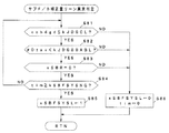
次に、上述した空燃比フィードバック制御ルーチンのステップS2で実行される目標空燃比λTgの設定について説明する。この目標空燃比λTgは、図3に示す目標空燃比設定ルーチンにて設定される。 Next, the setting of the target air-fuel ratio λTg executed in step S2 of the air-fuel ratio feedback control routine described above will be described. This target air-fuel ratio λTg is set by a target air-fuel ratio setting routine shown in FIG.
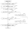
このルーチンでは、先ず、ステップS11で、リヤO2センサ11の出力値VO2[V]を読込む。続く、ステップS12で、この出力値VO2に基づき下流側空燃比RO2がリーン側にあるかリッチ側にあるかを調べ、前回の空燃比との比較において比例積分制御等によりサブフィードバック補正値αO2を設定する。
In this routine, first, in step S11, the output value VO2 [V] of the
次いで、ステップS13へ進み、ガード中心値Sgdoを読込む。このガード中心値Sgdoは、後述する図7に示すガード中心値設定ルーチンにて設定される。尚、ガード中心値Sgdoの初期値は0である。 Subsequently, it progresses to step S13 and the guard center value Sgdo is read. This guard center value Sgdo is set by a guard center value setting routine shown in FIG. The initial value of the guard center value Sgdo is 0.
そして、サブフィードバック補正値αO2と、ガード中心値Sgdoに予め設定したリッチ幅Rgdoを加算して設定したリッチ側ガード値(Sgdo+Rgdo)とを比較し、αO2>Sgdo+Rgdoのリッチ側ガード値を超えているときは、ステップS15へ分岐し、サブフィードバック補正値αO2をリッチ側ガード値で制限して(αO2←Sgdo+Rgdo)、ステップS18へ進む。 Then, the sub feedback correction value αO2 is compared with the rich side guard value (Sgdo + Rgdo) set by adding the preset rich width Rgdo to the guard center value Sgdo, and exceeds the rich side guard value of αO2> Sgdo + Rgdo. If so, the process branches to step S15, where the sub feedback correction value αO2 is limited by the rich guard value (αO2 ← Sgdo + Rgdo), and the process proceeds to step S18.
又、ステップS14で、αO2≦Sgdo+Rgdoのリッチ側ガード値以下のときは、ステップS16へ進み、サブフィードバック補正値αO2と、ガード中心値Sgdoから、予め設定したリーン幅Lgdoを減算して設定したリーン側ガード値(Sgdo−Lgdo)とを比較する。 If it is determined in step S14 that αO2 ≦ Sgdo + Rgdo is less than or equal to the rich guard value, the process proceeds to step S16, and the lean value set by subtracting a preset lean width Lgdo from the sub-feedback correction value αO2 and the guard center value Sgdo. The side guard value (Sgdo-Lgdo) is compared.
そして、αO2<Sgdo−Lgdoのリーン側ガード値を下回っているときは、ステップS17へ分岐し、サブフィードバック補正値αO2をリーン側ガード値で制限して(αO2←Sgdo−Lgdo)、ステップS18へ進む。 If αO2 <Sgdo-Lgdo is less than the lean guard value, the process branches to step S17, where the sub-feedback correction value αO2 is limited by the lean guard value (αO2 ← Sgdo-Lgdo), and the process proceeds to step S18. move on.
又、αO2≧Sgdo−Lgdoのリーン側ガード値以上のときは、サブフィードバック補正値αO2が、ガードウインドウ(Sgdo−Lgdo≦αO2≦Sgdo+Rgdo)に収まっているため、そのままステップS18へ進む。 On the other hand, when αO2 ≧ Sgdo−Lgdo is greater than or equal to the lean guard value, the sub feedback correction value αO2 is within the guard window (Sgdo−Lgdo ≦ αO2 ≦ Sgdo + Rgdo), so the process directly proceeds to step S18.
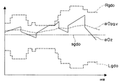
尚、図14に示すように、運転中のリッチ幅Rgdo、及びリーン幅Lgdoは、エンジン負荷によって変動する可変値である。 As shown in FIG. 14, the rich width Rgdo and the lean width Lgdo during operation are variable values that vary depending on the engine load.
ステップS18では、サブフィードバック補正値αO2に基づき目標空燃比λTgを補正して、今回の目標空燃比λTgを設定し、ルーチンを抜ける。 In step S18, the target air-fuel ratio λTg is corrected based on the sub-feedback correction value αO2, the current target air-fuel ratio λTg is set, and the routine is exited.
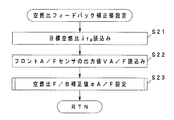
次に、上述した空燃比フィードバック制御ルーチンのステップS3で実行される空燃比フィードバック補正値αA/Fの設定について説明する。この空燃比フィードバック補正値αA/Fは、図4に示す空燃比フィードバック補正値設定ルーチンにて設定される。 Next, the setting of the air-fuel ratio feedback correction value αA / F executed in step S3 of the above-described air-fuel ratio feedback control routine will be described. This air-fuel ratio feedback correction value αA / F is set by an air-fuel ratio feedback correction value setting routine shown in FIG.
このルーチンでは、先ず、ステップS21で、目標空燃比λTgを読込み、続くステップS22で、フロントA/Fセンサ10の出力値VA/F[V]を読込む。
In this routine, first, in step S21, the target air-fuel ratio λTg is read, and in the subsequent step S22, the output value VA / F [V] of the front A /
その後、ステップS23で、フロントA/Fセンサ10の出力値VA/Fに対応する空燃比を算出し、この空燃比が目標空燃比に収束するように空燃比フィードバック補正値αA/Fを、比例積分制御等により設定して、ルーチンを抜ける。
Thereafter, in step S23, the air-fuel ratio corresponding to the output value VA / F of the front A /
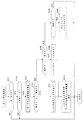
一方、空燃比制御が実行されると、そのバックグラウンドにおいて、図5に示すリヤO2センサのリッチ/リーン累積時間比判定ルーチン、及び、図6に示すサブフィードバック平均値判定ルーチンが実行される。 On the other hand, when the air-fuel ratio control is executed, a rich / lean cumulative time ratio determination routine of the rear O2 sensor shown in FIG. 5 and a sub-feedback average value determination routine shown in FIG. 6 are executed in the background.
図5に示すリヤO2センサのリッチ/リーン累積時間比判定ルーチンでは、先ず、ステップS31で、実行条件が成立しているか否かを調べる。実行条件は、サブフィードバック制御が実行されているか否かで判定し、サブフィードバック制御が実行されているときは、実行条件成立と判定してステップS32へ進む。一方、サブフィードバック制御が実行されてないとき、すなわち、例えば図12の左側に示すようにリヤO2センサ11の出力値VO2が大きく変動しているときは、実行条件不成立と判定し、ルーチンを抜ける。
In the rich / lean cumulative time ratio determination routine of the rear O2 sensor shown in FIG. 5, first, in step S31, it is checked whether or not an execution condition is satisfied. The execution condition is determined based on whether or not the sub feedback control is being executed. When the sub feedback control is being executed, it is determined that the execution condition is satisfied, and the process proceeds to step S32. On the other hand, when the sub-feedback control is not executed, that is, when the output value VO2 of the
尚、実行条件が不成立であっても、後述する算出累積時間カウンタのカウント値csbfacは、図12の符号A,Bで示すようにクリアされず、実行条件が成立するまで待機される。従って、後述するA/Fリッチ累積時間カウンタのカウント値csbR、A/Fリーン累積時間カウンタのカウント値csbLもクリアされずに待機状態となる。 Even if the execution condition is not satisfied, a count value csbfac of a calculated cumulative time counter, which will be described later, is not cleared as indicated by reference signs A and B in FIG. 12, and the process waits until the execution condition is satisfied. Therefore, a count value csbR of an A / F rich cumulative time counter, which will be described later, and a count value csbL of an A / F lean cumulative time counter are not cleared and enter a standby state.
又、ステップS32へ進むと、リヤO2センサ11の出力値VO2[V]の目標値VOTg[V](理論空燃比付近の値)を読込む。次いで、ステップS33へ進み、リヤO2センサ11の出力値VO2[V]を読込む。
In step S32, the target value VOTg [V] (value near the theoretical air-fuel ratio) of the output value VO2 [V] of the
次いで、ステップS34へ進み、リヤO2センサ11の出力値VO2と、目標値VOTgとを比較する。そして、VO2≧VOTgの空燃比リッチのときは、ステップS35へ進み、VO2<VOTgの空燃比リーンのときは、ステップS36へ分岐する。ステップS35へ進むと、空燃比リッチ累積時間カウンタのカウント値csbRをカウントアップして(csbR←csbR+1)、ステップS37へ進む。又、ステップS36へ進むと、空燃比リーン累積時間カウンタのカウント値csbLをカウントアップして(csbL←csbL+1)、ステップS37へ進む。
In step S34, the output value VO2 of the
ステップS37では、算出累積時間カウンタのカウント値csbfacをカウントアップし(csbfac←csbfac+1)、ステップS38へ進み、算出累積時間カウンタのカウント値csbfacと設定時間To(例えば、5sec,10sec等、予め設定されている固定値)とを比較し、csbfac<Toの設定時間Toに達していないときは、そのままルーチンを抜ける。 In step S37, the count value csbfac of the calculated cumulative time counter is counted up (csbfac ← csbfac + 1), the process proceeds to step S38, and the count value csbfac of the calculated cumulative time counter and a set time To (for example, 5 sec, 10 sec, etc. are set in advance). If the set time To of csbfac <To has not been reached, the routine is exited as it is.
一方、csbfac≧Toの設定時間Toに達したときは、ステップS39へ進み、A/Fリッチ累積時間カウンタのカウント値csbRとA/Fリーン累積時間カウンタのカウント値csbLとの比であるリッチ/リーン累積時間比sbfaを算出する(sbfa←csbR/csbL)。 On the other hand, when the set time To of csbfac ≧ To has been reached, the process proceeds to step S39, where the ratio of the count value csbR of the A / F rich cumulative time counter to the count value csbL of the A / F lean cumulative time counter is rich / The lean cumulative time ratio sbfa is calculated (sbfa ← csbR / csbL).
次いで、ステップS40で累積時間比判定経験フラグxSBFをセットする(xSBF←1)。この累積時間比判定経験フラグxSBFの初期値は0であり、後述するガード中心値設定ルーチンにおいて読込まれる。 Next, in step S40, the cumulative time ratio determination experience flag xSBF is set (xSBF ← 1). The initial value of this cumulative time ratio determination experience flag xSBF is 0, and is read in a guard center value setting routine described later.
その後、ステップS41へ進み、ステップS41〜S44で、リッチ/リーン累積時間比sbfaに基づき、空燃比がリッチシフトしているか、リーンシフトしているかを調べる。 Thereafter, the process proceeds to step S41, and in steps S41 to S44, it is checked whether the air-fuel ratio is rich-shifted or lean-shifted based on the rich / lean cumulative time ratio sbfa.
ステップS41では、リッチ/リーン累積時間比sbfaとリッチシフト判定値tJDGRとを比較し、sbfa>tJDGRのときは、空燃比がリッチシフトしていると判定し、ステップS42へ進み、累積時間比リッチシフト経験フラグxSBFRをセットし(xSBFR←1)、ステップS45へ進む。 In step S41, the rich / lean cumulative time ratio sbfa is compared with the rich shift determination value tJDGR. If sbfa> tJDGR, it is determined that the air-fuel ratio is richly shifted, and the process proceeds to step S42, where the cumulative time ratio rich The shift experience flag xSBFR is set (xSBFR ← 1), and the process proceeds to step S45.
又、sbfa≦tJDGRのときは、ステップS43へ分岐し、リッチ/リーン累積時間比sbfaとリーンシフト判定値tJDGLとを比較する。そして、sbfa≧tJDGLのとき、すなわち、リッチ/リーン累積時間比sbfaが、リッチシフト判定値tJDGRとリーンシフト判定値tJDGLとの間にあるとき(tJDGR≧sbfa≧tJDGL)は、サブフィードバック補正値αO2が理論空燃比付近で制御されていると判断し、ステップS45へジャンプする。一方、sbfa<tJDGLのときは、空燃比がリーンシフトしていると判定し、ステップS44へ進み、累積時間比リーンシフト経験フラグxSBFLをセットし(xSBFL←1)、ステップS45へ進む。 If sbfa ≦ tJDGR, the process branches to step S43 to compare the rich / lean cumulative time ratio sbfa with the lean shift determination value tJDGL. When sbfa ≧ tJDGL, that is, when the rich / lean cumulative time ratio sbfa is between the rich shift determination value tJDGR and the lean shift determination value tJDGL (tJDGR ≧ sbfa ≧ tJDGL), the sub feedback correction value αO2 Is determined to be controlled near the stoichiometric air-fuel ratio, and the routine jumps to step S45. On the other hand, when sbfa <tJDGL, it is determined that the air-fuel ratio has undergone a lean shift, the process proceeds to step S44, the cumulative time ratio lean shift experience flag xSBFL is set (xSBFL ← 1), and the process proceeds to step S45.
ステップS45では、A/Fリッチ累積時間カウンタのカウント値csbR、A/Fリーン累積時間カウンタのカウント値csbL、及び算出累積時間カウンタのカウント値csbfacをクリアして(csbR←0,csbL←0,csbfac←0)、ルーチンを抜ける。 In step S45, the count value csbR of the A / F rich cumulative time counter, the count value csbL of the A / F lean cumulative time counter, and the count value csbfac of the calculated cumulative time counter are cleared (csbR ← 0, csbL ← 0, csbfac ← 0), the routine is exited.
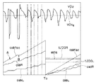
ここで、図12、図13に示すタイムチャートに従い、上述したリヤO2センサのリッチ/リーン累積時間比判定ルーチンで設定されるA/Fリッチ累積時間カウンタのカウント値csbR、A/Fリーン累積時間カウンタのカウント値csbL、及びリッチ/リーン累積時間比sbfaの設定を例示する。 Here, according to the time charts shown in FIGS. 12 and 13, the count values csbR and A / F lean accumulated time of the A / F rich accumulated time counter set in the rich / lean accumulated time ratio determination routine of the rear O2 sensor described above. The setting of the count value csbL of the counter and the rich / lean cumulative time ratio sbfa is illustrated.
同図に示すように、A/Fリッチ累積時間カウンタのカウント値csbRは、リヤO2センサ11の出力値VO2が空燃比リッチを検出している間(VO2≧VOTg)は、インクリメントされ、空燃比リーンを検出している間(VO<VOTg)は停止している(ステップS35)。逆に、A/Fリーン累積時間カウンタのカウント値csbLは、リヤO2センサ11の出力値VO2が空燃比リッチを検出している間(VO2≧VOTg)は停止され、空燃比リーンを検出している間(VO2<VOTg)はインクリメントされる(ステップS36)。又、実行条件が不成立時は成立するまで待機状態となる(ステップS31)。
As shown in the figure, the count value csbR of the A / F rich cumulative time counter is incremented while the output value VO2 of the
そして、算出累積時間カウンタのカウント値csbfacが設定時間Toに達したとき、A/Fリッチ累積時間カウンタのカウント値csbRとA/Fリーン累積時間カウンタのカウント値csbLとの比であるリッチ/リーン累積時間比sbfa(sbfa←csbR/csbL)を算出し(ステップS39)、このリッチ/リーン累積時間比sbfaが、リッチシフト判定値tJDGRとリーンシフト判定値tJDGLとの間に収まっているか否かを判定する(ステップS41〜S44)。同時に、各カウント値csbR,csbL,csbfacをクリアする(ステップS45)。 When the count value csbfac of the calculated cumulative time counter reaches the set time To, the rich / lean ratio is a ratio between the count value csbR of the A / F rich cumulative time counter and the count value csbL of the A / F lean cumulative time counter. An accumulated time ratio sbfa (sbfa ← csbR / csbL) is calculated (step S39), and whether or not the rich / lean accumulated time ratio sbfa is within the rich shift determination value tJDGR and the lean shift determination value tJDGL. Determination is made (steps S41 to S44). At the same time, the count values csbR, csbL, and csbfac are cleared (step S45).
又、図6に示すサブフィードバック平均値判定ルーチンでは、先ず、ステップS51で、実行条件が成立しているか否かを調べる。実行条件は、始動後、サブフィードバック制御が設定時間以上実行されているか否かで判断し、サブフィードバック制御が設定時間以上継続されているときは、実行条件成立と判定して、ステップS52へ進む。又、サブフィードバック制御の実行時間が設定時間に達していないときは、実行条件不成立と判定し、そのままルーチンを抜ける。尚、このとき後述するサブフィードバック平均値αO2avが算出されているときは、その値が保持されている。 In the sub-feedback average value determination routine shown in FIG. 6, first, in step S51, it is checked whether or not an execution condition is satisfied. The execution condition is determined based on whether or not the sub feedback control is executed for a set time or more after the start. When the sub feedback control is continued for the set time or more, it is determined that the execution condition is satisfied, and the process proceeds to step S52. . If the execution time of the sub feedback control has not reached the set time, it is determined that the execution condition is not satisfied, and the routine is exited as it is. At this time, when a sub feedback average value αO2av, which will be described later, is calculated, the value is held.
ステップS52へ進むと、サブフィードバック補正値αO2を読込み、ステップS53で、サブフィードバック補正値αO2の平均値(以下「サブフィードバック平均値」と称する)αO2avを、
αO2av←αO2av+(αO2−αO2av)×kFBAV
から算出する。尚、kFBAVは重み係数である。
In step S52, the sub-feedback correction value αO2 is read. In step S53, the average value (hereinafter referred to as “sub-feedback average value”) αO2av of the sub-feedback correction value αO2 is
αO2av ← αO2av + (αO2−αO2av) × kFBAV
Calculate from Note that kFBAV is a weighting factor.
尚、初回ルーチン実行時のサブフィードバック平均値αO2avは、サブフィードバック補正値αO2を代入して初期設定する(αO2av←αO2)。サブフィードバック平均値αO2avを0からではなく、サブフィードバック補正値αO2から開始するのは、後述するサブF/Bリーン異常判定ルーチン(図10参照)、及びサブF/Bリッチ異常判定ルーチン(図11参照)のステップS82、ステップS92において、サブフィードバック平均値αO2avは「常に判定値以上(以下)」を前提としているからである。 The sub-feedback average value αO2av at the time of execution of the first routine is initialized by substituting the sub-feedback correction value αO2 (αO2av ← αO2). The sub feedback average value αO2av starts from the subfeedback correction value αO2 instead of 0. The sub F / B lean abnormality determination routine (see FIG. 10) and the sub F / B rich abnormality determination routine (see FIG. 11) described later. This is because the sub-feedback average value αO2av is assumed to be “always greater than or equal to the determination value (below)” in steps S82 and S92.
次いで、ステップS54へ進み、サブフィードバック補正値αO2に応じて設定された設定値であるサブフィードバック平均値αO2avと、リーンシフト判定値(Sgdo−tSBAVL)とを比較する。そして、αO2av>Sgdo−tSBAVLのときは、ステップS55へ進み、サブフィードバック平均値リーンシフト判定フラグxSBAVLをクリアして(xSBAVL←0)、ステップS58へ進む。 Next, the process proceeds to step S54, and the sub-feedback average value αO2av, which is a set value set according to the sub-feedback correction value αO2, is compared with the lean shift determination value (Sgdo-tSBAVL). If αO2av> Sgdo−tSBAVL, the process proceeds to step S55, the sub-feedback average value lean shift determination flag xSBAVL is cleared (xSBAVL ← 0), and the process proceeds to step S58.
一方、αO2av≦Sgdo−tSBAVLのときは、ステップS56へ分岐し、サブフィードバック平均値αO2avと、サブフィードバック平均値リッチシフト判定値(Sgdo+tSBAVR)とを比較する。そして、αO2av<Sgdo+tSBAVRのときは、ステップS57へ進み、サブフィードバック平均値リッチシフト判定フラグxSBAVRをクリアして(xSBAVR←0)ステップS58へ進む。 On the other hand, when αO2av ≦ Sgdo−tSBAVL, the process branches to step S56, and the sub-feedback average value αO2av is compared with the sub-feedback average value rich shift determination value (Sgdo + tSBAVR). If αO2av <Sgdo + tSBAVR, the process proceeds to step S57, the sub-feedback average value rich shift determination flag xSBAVR is cleared (xSBAVR ← 0), and the process proceeds to step S58.
尚、両シフト判定フラグxSBAVL、xSBAVRは、サブフィードバック平均値αO2avに偏りが生じているか否か、すなわち、リーンシフト、或いはリッチシフトしているか否かを示すもので、初期値は1である。従って、サブフィードバック平均値αO2avが、リーンシフト判定値(Sgdo−tSBAVL)とリッチシフト判定値(Sgdo+tSBAVR)との間に、一度でも収まった経験をすると、両シフト判定フラグxSBAVL、xSBAVRはクリアされる。換言すれば、サブフィードバック平均値αO2avが、リーンシフト判定値(Sgdo−tSBAVL)とリッチシフト判定値(Sgdo+tSBAVR)との間に、一度も収まらない場合は、イグニッションスイッチをOFFするまで、各シフト判定フラグxSBAVL、xSBAVRのいずれかは0にセットされないと言うことになる。 Note that both shift determination flags xSBAVL and xSBAVR indicate whether or not the sub-feedback average value αO2av is biased, that is, whether or not a lean shift or a rich shift is performed. The initial value is 1. Therefore, if the sub feedback average value αO2av falls within the range between the lean shift determination value (Sgdo-tSBAVVL) and the rich shift determination value (Sgdo + tSBAVR), both shift determination flags xSBAVL and xSBAVR are cleared. . In other words, if the sub-feedback average value αO2av never falls between the lean shift determination value (Sgdo−tSBAVL) and the rich shift determination value (Sgdo + tSBAVR), each shift determination is made until the ignition switch is turned OFF. One of the flags xSBAVL and xSBAVVR is not set to 0.
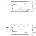
図15(a)には、サブフィードバック平均値αO2avがリーンシフトしている状態を示し、同図(b)には、リッチシフトしている状態を示す。何れの場合も、破線で示すように、サブフィードバック平均値αO2avが、一方へシフトしている状態から一度でもリーンシフト判定値(Sgdo−tSBAVL)、或いはリッチシフト判定値(Sgdo+tSBAVR)を横切ったとき、リーンシフト判定フラグxSBAVL、或いはリッチシフト判定フラグxSBAVRが0にセットされる。 FIG. 15A shows a state where the sub-feedback average value αO2av is lean-shifted, and FIG. 15B shows a state where the sub-feedback average value αO2av is rich-shifted. In either case, as shown by the broken line, when the sub-feedback average value αO2av crosses the lean shift determination value (Sgdo-tSBAVVL) or the rich shift determination value (Sgdo + tSBAVVR) even once from the state of shifting to one side. The lean shift determination flag xSBAVL or the rich shift determination flag xSBAVR is set to 0.
次いで、ステップS58へ進むと、サブフィードバック平均値αO2avとガード中心値Sgdoとを比較する。 Next, in step S58, the sub feedback average value αO2av and the guard center value Sgdo are compared.
そして、αO2av>Sgdoのときは、ステップS59へ進み、サブフィードバックリッチ補正実施経験フラグxSBRをセットして(xSBR←1)、ルーチンを終了する。一方、αO2av≦SgdoのときはステップS60へ分岐し、サブフィードバックリーン補正実施経験フラグxSBLをセットして(xSBL←1)、ルーチンを終了する。 If αO2av> Sgdo, the process proceeds to step S59, the sub feedback rich correction execution experience flag xSBR is set (xSBR ← 1), and the routine is terminated. On the other hand, if αO2av ≦ Sgdo, the process branches to step S60, the sub feedback lean correction execution experience flag xSBL is set (xSBL ← 1), and the routine is terminated.
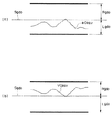
両実施経験フラグxSBR,xSBLは、ガード中心値Sgdoをリッチ側或いはリーン側へ移動させたときに、ガード中心値Sgdoの移動方向に対してサブフィードバック平均値αO2avの制御が行われているか否かの経験の有無を調べるものである。図16(a)には、ガード中心値Sgdoをリッチ側へ移動させた状態が示されており、同図(b)には、ガード中心値Sgdoをリーン側へ移動させた状態が示されている。両実施経験フラグxSBR,xSBLの初期値は0であり、サブフィードバック平均値αO2avが一度でも、ガード中心値Sgdoを横切ってオフセット方向へ制御した場合に、1にセットされる。 Both execution experience flags xSBR and xSBL indicate whether or not the sub feedback average value αO2av is controlled with respect to the movement direction of the guard center value Sgdo when the guard center value Sgdo is moved to the rich side or the lean side. It is to check the existence of experience. FIG. 16A shows a state where the guard center value Sgdo is moved to the rich side, and FIG. 16B shows a state where the guard center value Sgdo is moved to the lean side. Yes. The initial values of both implementation experience flags xSBR and xSBL are 0, and are set to 1 when the sub-feedback average value αO2av is once controlled across the guard center value Sgdo in the offset direction.
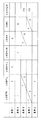
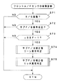
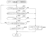
次に、図7に示すガード中心値設定ルーチンについて説明する。このルーチンでは、上述したリッチ/リーン累積時間比sbfa、サブフィードバック平均値αO2avの状態に基づいて設定された各フラグxSBFR,xSBFL,xSBAVL,xSBAVR,xSBR,xSBLから、次回の運転時において設定するガード中心値Sgdoの移動量を決定するものである。 Next, the guard center value setting routine shown in FIG. 7 will be described. In this routine, a guard to be set at the next operation is determined from each flag xSBFR, xSBFL, xSBAVL, xSBAVR, xSBR, xSBL set based on the rich / lean cumulative time ratio sbfa and the sub feedback average value αO2av. The amount of movement of the center value Sgdo is determined.
すなわち、先ず、ステップS61では、イグニッションスイッチがOFFか否かを調べ、ONのときは、OFFするまで待機する。そして、イグニッションスイッチがOFFされたとき、ステップS62へ進む。尚、本形態で作用するエンジンは、セルフシャット機能を有しており、イグニッションスイッチをOFFした後も、ECU20に対しては設定時間だけ通電が継続されている。 That is, first, in step S61, it is checked whether or not the ignition switch is OFF. If it is ON, the process waits until it is turned OFF. When the ignition switch is turned off, the process proceeds to step S62. Note that the engine that operates in this embodiment has a self-shut function, and the ECU 20 is continuously energized for a set time even after the ignition switch is turned off.
ステップS62では、累積時間比判定経験フラグxSBFの値を参照し、xSBF=1の累積時間比判定経験済みの場合はステップS63へ進み、又、xSBF=0の累積時間比未判定のときはルーチンを抜ける。 In step S62, the value of the cumulative time ratio determination experience flag xSBF is referred to, and if the cumulative time ratio determination of xSBF = 1 has been experienced, the process proceeds to step S63, and if the cumulative time ratio of xSBF = 0 is not determined, the routine is executed. Exit.
そして、ステップS63へ進むと、ガード中心値移動条件を設定する。図8に示すように、ガード中心値移動条件は、各フラグxSBFR,xSBFL,xSBAVL,xSBAVR,xSBR,xSBLの値、及び後述するサブフィードバックガード操作回数カウンタのカウント値cobdgdに基づき、条件1〜5に区分されている。以下、各条件について説明する。 In step S63, a guard center value movement condition is set. As shown in FIG. 8, the guard center value movement condition is based on the values of the respective flags xSBFR, xSBFL, xSBAVL, xSBAVR, xSBR, xSBL, and the count value cobdgd of a sub feedback guard operation number counter described later. It is divided into. Hereinafter, each condition will be described.
条件1:xSBFL=1(今回の運転時に累積時間比sbfaがリーンシフトを経験済み)、且つ、xSBAVL=1(今回の運転中、サブフィードバック平均値αO2avが常時リーンシフト判定値(Sgdo-tSBAVL)以下)、且つ、xSBR=0(今回の運転時にサブフィードバック平均値αO2avがリッチ補正を未経験)であること(図15(a)参照)。 Condition 1: xSBFL = 1 (cumulative time ratio sbfa has experienced a lean shift during this operation), and xSBAVL = 1 (during this operation, sub-feedback average value αO2av is always a lean shift determination value (Sgdo-tSBAVL) XSBR = 0 (sub-feedback average value αO2av has not experienced rich correction during the current operation) (see FIG. 15A).
条件2:xSBFR=1(今回の運転時に累積時間比sbfaがリッチシフトを経験済み)、且つ、xSBAVR=1(今回の運転中、サブフィードバック平均値αO2avが常時リッチシフト判定値(Sgdo+tSBAVR)以上)、且つ、xSBL=0(今回の運転時にサブフィードバック平均値αO2avがリーン補正を未経験)であること(図15(b)参照)。 Condition 2: xSBFR = 1 (cumulative time ratio sbfa has experienced a rich shift during the current operation), and xSBAVR = 1 (during the current operation, the sub feedback average value αO2av is always the rich shift determination value (Sgdo + tSBAVR). And xSBL = 0 (the sub feedback average value αO2av has not experienced lean correction at the time of the current operation) (see FIG. 15B).
条件3:cobdgdが0よりも大きく(cobdgd>0)、且つ、xSBFL=1或いはxSBR=0であること。 Condition 3: cobdgd is larger than 0 (cobdgd> 0) and xSBFL = 1 or xSBR = 0.
条件4:cobdgdが0未満で(cobdgd<0)、xSBFR=1或いはxSBL=0であること。 Condition 4: cobdgd is less than 0 (cobdgd <0) and xSBFR = 1 or xSBL = 0.
条件5:xSBFR=1、且つ、xSBFL=1であること。 Condition 5: xSBFR = 1 and xSBFL = 1.
となる。 It becomes.
そして、ステップS64〜66で、今回の運転がどの条件に対応しているかを判定する。条件1、或いは条件3のときは、図15(a)に示すように、ガード中心値Sgdoがリッチ側へ過度に移動されていると判断し、ステップS64からステップS67へ進み、サブフィードバックガード操作回数カウンタのカウント値cobdgdをデクリメントして(cobdgd←cobdgd−1)、ステップS70へ進む。
Then, in steps S64 to 66, it is determined to which condition the current operation corresponds. When
又、条件2、或いは4のときは、図15(b)に示すように、ガード中心値Sgdoがリーン側へ過度に移動されていると判断し、ステップS65からステップS68へ進み、サブフィードバック(サブF/B)ガード操作回数カウンタのカウント値cobdgdをインクリメントして(cobdgd←cobdgd+1)、ステップS70へ進む。
In the case of
又、条件5のときは、今回の運転時にリッチシフトとリーンシフトとを経験しているため、ステップS66からステップS69へ進み、ガード中心値Sgdoと、サブF/Bガード操作回数カウンタのカウント値cobdgdとを共に0に戻して(Sgdo←0,cobdgd←0)として、ルーチンを終了する。 In the case of condition 5, since rich shift and lean shift are experienced during the current operation, the process proceeds from step S66 to step S69, where the guard center value Sgdo and the count value of the sub F / B guard operation number counter are counted. Both cobdgd are returned to 0 (Sgdo ← 0, cobdgd ← 0), and the routine is terminated.
又、何れの条件にも適合しない場合は、そのままルーチンを終了し、サブF/Bガード操作回数カウンタのカウント値cobdgd、ガード中心値Sgdoを維持する。 一方、ステップS67或いはS68から、ステップS70へ進むと、カウント値cobdgdに基づき、テーブル検索、或いは演算によりガード中心値Sgdoの移動量を設定して、ルーチンを終了する。 If none of the conditions is met, the routine is terminated as it is, and the count value cobdgd and the guard center value Sgdo of the sub F / B guard operation number counter are maintained. On the other hand, when the process proceeds from step S67 or S68 to step S70, the movement amount of the guard center value Sgdo is set by table search or calculation based on the count value cobdgd, and the routine is terminated.
ガード中心値Sgdoの移動量は、カウント値cobdgdの増減にほぼ比例して設定される。従って、ステップS67でカウント値cobdgdがデクリメントされた場合、次回の運転時に実行される目標空燃比設定ルーチン(図3参照)において読込まれるガード中心値Sgdoは減少方向に移動され、リッチ側への過度の移動が修正される。又、ステップS68でカウント値cobdgdがインクリメントされた場合は、ガード中心値Sgdoは増加方向に移動されるため、リーン側への過度の移動が修正される。 The movement amount of the guard center value Sgdo is set almost in proportion to the increase / decrease of the count value cobdgd. Therefore, when the count value cobdgd is decremented in step S67, the guard center value Sgdo read in the target air-fuel ratio setting routine (see FIG. 3) executed at the next operation is moved in the decreasing direction, Excessive movement is corrected. If the count value cobdgd is incremented in step S68, the guard center value Sgdo is moved in the increasing direction, so that excessive movement toward the lean side is corrected.
以上の結果、例えば、フロントA/Fセンサ10の故障により、実際には空燃比がλ=1.1であるにも拘わらず、λ=1.0と誤検出した場合、リヤO2センサ11で検出する空燃比はリーンとなるため、図14に示すように、サブフィードバック補正値αO2はリッチ側へ偏った制御となる。その結果、サブフィードバック平均値αO2avはガード中心値Sgdoからリッチ側へシフトされた値となる。このような場合、すなわちサブフィードバック平均値αO2avが、図8の条件2或いは条件4(図15(b)参照)にある場合は、次回の運転時においては、ガード中心値Sgdoがリッチ側へ移動されるため、サブフィードバック平均値αO2avはガード中心値Sgdo側へシフトされて、良好なサブフィードバック制御性を得ることが出来る。
As a result, for example, if the air-fuel ratio is actually λ = 1.1 due to a failure of the front A /
逆に、フロントA/Fセンサ10が、実際には空燃比がλ=0.9であるにも拘わらず、λ=1.0と誤検出した場合、リヤO2センサ11で検出する空燃比はリッチとなるため、サブフィードバック補正値αO2はリーン側へ偏った制御となる。その結果、サブフィードバック平均値αO2avはガード中心値Sgdoからリーン側へシフトされる。このような場合、すなわち、サブフィードバック平均値αO2avが、図8の条件1或いは条件3(図15(a)参照)にある場合は、次回の運転時においては、ガード中心値Sgdoがリーン側へ移動されるため、良好なサブフィードバック制御性を得ることが出来る。
Conversely, if the front A /
従って、フロントA/Fセンサ10の故障により上流側空燃比FA/Fが正確に検出されない場合であっても、リヤO2センサ11で検出した下流側空燃比RO2に基づいて、良好な空燃比フィードバック制御を行うことができる。すなわち、フロントA/Fセンサ10の故障による空燃比誤検出を、リヤO2センサ11の検出値に基づいて設定されるサブフィードバック補正値αO2にて修正することができる。
Therefore, even if the upstream air-fuel ratio FA / F is not accurately detected due to a failure of the front A /
尚、本形態では、ガード中心値設定ルーチンを、イグニッションスイッチをOFF後、すなわち、1運転で1回行うようにしているが、運転中において設定時間毎に行うようにしても良い。 In this embodiment, the guard center value setting routine is performed once after the ignition switch is turned off, that is, once in one operation, but may be performed every set time during the operation.
次に、図9に示すフローチャートに従い、フロントA/Fセンサ10の故障診断について説明する。このルーチンは、イグニッションスイッチをONした後、空燃比制御のバックグラウンドにおいて、所定周期毎に実行される。
Next, failure diagnosis of the front A /
先ず、ステップS71で、エンジン1が始動しているか否かを、エンジン回転数、或いはスタータスイッチのONからOFFへの切換え等に基づいて調べる。そして、エンジン1が始動していないときは、ルーチンを抜け、始動するまで待機する。
First, in step S71, it is checked whether or not the
一方、エンジン1が始動すると、ステップS72へ進み、サブフィードバック条件が成立しているか否かを調べる。サブフィードバック条件は、サブフィードバック補正値αO2が出力されているか否かで判断し、サブフィードバック補正値αO2が出力されているときは、サブフィードバック条件成立と判断して、ステップS73へ進む。一方、サブフィードバック補正値αO2が出力されていないときは、そのままルーチンを抜ける。
On the other hand, when the
ステップS73へ進むと、累積時間比判定経験フラグxSBFの値を参照し、xSBF=1、すなわち、累積時間比判定経験済みの場合はステップS74へ進み、xSBF=0、すなわち、未だ累積時間比判定が成されていないときは、そのままルーチンを抜ける。 In step S73, the value of the cumulative time ratio determination experience flag xSBF is referred to. If xSBF = 1, that is, if the cumulative time ratio determination has been experienced, the process proceeds to step S74, and xSBF = 0, that is, the cumulative time ratio determination is still in progress. If is not done, the routine is exited.
ステップS74へ進むと、サブF/Bリーン異常判定を行い、続く、ステップS75でサブF/Bリッチ異常判定を行った後、ルーチンを抜ける。 In step S74, the sub F / B lean abnormality determination is performed. After the sub F / B rich abnormality determination is performed in step S75, the routine is exited.
ステップS74のサブF/Bリーン異常判定は、図10に示すサブF/Bリーン異常判定ルーチンで実行される。 The sub F / B lean abnormality determination in step S74 is executed by a sub F / B lean abnormality determination routine shown in FIG.
このルーチンは、サブフィードバック補正値αO2がリーン側へ異常補正されているか否か、すなわち、ガード中心値Sgdoをリーン側へ移動させたにも拘わらず依然としてサブフィードバック補正値αO2がリーンシフトしているか否かを調べる。 In this routine, whether or not the sub-feedback correction value αO2 is abnormally corrected to the lean side, that is, whether or not the sub-feedback correction value αO2 is still lean-shifted even though the guard center value Sgdo is moved to the lean side. Check for no.
先ず、ステップS81で、サブF/Bガード操作回数カウンタのカウント値cobdgdとリーンオフセット判定値kJDGCLとを比較する。サブF/Bガード操作回数カウンタのカウント値cobdgdはガード中心値Sgdoの移動量を示している。ガード中心値Sgdoは、上述した図7に示すガード中心値設定ルーチンにおいて設定され、ガード中心値Sgdoがリッチ側へ過度に移動されているときはデクリメントされ(cobdgd←cobdgd−1)、リーン側へ過度に移動されているときはインクリメントされる(cobdgd←cobdgd+1)。 First, in step S81, the count value cobdgd of the sub F / B guard operation counter is compared with the lean offset determination value kJDGCL. The count value cobdgd of the sub F / B guard operation number counter indicates the movement amount of the guard center value Sgdo. The guard center value Sgdo is set in the above-described guard center value setting routine shown in FIG. 7. When the guard center value Sgdo is excessively moved to the rich side, it is decremented (cobdgd ← cobdgd-1) and to the lean side. When it is moved excessively, it is incremented (cobdgd ← cobdgd + 1).
そして、cobdgd≦kJDGCLのガード中心値Sgdoがリーンオフセット判定値kJDGCL以下にオフセットされているとき、すなわちガード中心値Sgdoがリーン側へ過度に移動されているときは、ステップS82へ進む。又、cobdgd>kJDGCLのときは、正常と判断し、ステップS86へ分岐する。 When the guard center value Sgdo of cobdgd ≦ kJDGCL is offset below the lean offset determination value kJDGCL, that is, when the guard center value Sgdo is excessively moved to the lean side, the process proceeds to step S82. If cobdgd> kJDGCL, it is determined as normal and the process branches to step S86.
又、ステップS82へ進むと、サブフィードバック平均値αO2avとサブF/Bリーンオフセット判定値kJDGSBABLとを比較する。このサブF/Bリーンオフセット判定値kJDGSBABLは、サブフィードバック平均値αO2avがリーン側ガード値(Sgdo−Lgdo)に貼り付き傾向(貼り付いた場合も含む)があるかどうか判定するもので、リーン側ガード値(Sgdo−Lgdo)よりもややリッチ側に設定されている。 In step S82, the sub feedback average value αO2av is compared with the sub F / B lean offset determination value kJDGSBABL. This sub F / B lean offset judgment value kJDGSBABL judges whether or not the sub feedback average value αO2av has a sticking tendency (including the case of sticking) to the lean side guard value (Sgdo-Lgdo). It is set slightly richer than the guard value (Sgdo-Lgdo).
そして、αO2av≧kJDGSBABLのときは、ガード中心値Sgdoをリーン側へオフセットさせたことで、サブフィードバック平均値αO2avのリーン側への貼り付き傾向が解消されたため、ステップS86へ分岐する。 When αO2av ≧ kJDGSBABL, the tendency to stick the sub-feedback average value αO2av to the lean side is eliminated by offsetting the guard center value Sgdo to the lean side, and the process branches to step S86.
又、αO2av<kJDGSBABLのときは、ガード中心値Sgdoをリーン側へオフセットさせても、依然としてサブフィードバック平均値αO2avのリーン側への貼り付き傾向が解消されない、すなわち、リーン側への補正不足と判断し、ステップS83へ進み、サブF/Bリッチ補正実施経験フラグxSBRがクリアされているか否かを調べる。 Further, when αO2av <kJDGSBABL, even if the guard center value Sgdo is offset to the lean side, the tendency of sticking of the sub feedback average value αO2av to the lean side is still not resolved, that is, it is determined that the correction to the lean side is insufficient. Then, the process proceeds to step S83 to check whether or not the sub F / B rich correction execution experience flag xSBR is cleared.
xSBR=0、すなわち、サブフィードバック平均値αO2avが、一度も、ガード中心値Sgdoを横切ってリッチ方向へ制御されていない場合は、ステップS84へ進み、又、xSBR=1、すなわち、サブフィードバック平均値αO2avがガード中心値Sgdoを横切った経験があるときは、ステップS86へ分岐する。 If xSBR = 0, that is, the sub feedback average value αO2av has never been controlled in the rich direction across the guard center value Sgdo, the process proceeds to step S84, and xSBR = 1, that is, the sub feedback average value If αO2av has experience of crossing the guard center value Sgdo, the process branches to step S86.
ステップS81,ステップS82、或いはステップS83からステップS86へ分岐すると、サブF/Bリーン異常判定フラグxSBFSYSLをクリアすると共に、後述する異常判定タイマのカウント値timをクリアして(xSBFSYSL←0,tim←0)、ルーチンを抜け、図9のステップS76へ進む。 When branching from step S81, step S82, or step S83 to step S86, the sub F / B lean abnormality determination flag xSBFSSYSL is cleared and a count value tim of an abnormality determination timer described later is cleared (xSBFSYSL ← 0, tim ←). 0) Exit the routine and proceed to step S76 in FIG.
又、ステップS84へ進むと、異常判定時間計測タイマのカウント値timと設定時間kSBFSYSNG(10min,20min等)とを比較し、異常判定時間Timが設定時間kSBFSYSNGに達していないときは(tim<kSBFSYSNG)、ステップS81へ戻り、再度、異常判定を行う。 In step S84, the count value tim of the abnormality determination time measurement timer is compared with the set time kBBFSYSNG (10 min, 20 min, etc.). When the abnormality determination time Tim has not reached the set time kBBFSYSNG (tim <kSBFSSYNG). ), The process returns to step S81, and abnormality determination is performed again.
そして、異常判定時間Timが設定時間kSBFSYSNGに達したときは(tim≧kSBFSYSNG)、ステップS85へ進み、サブF/Bリーン異常判定フラグxSBFSYSLをセットして(xSBFSYSL←1)、ルーチンを抜け、図9のステップS75へ進む。 When the abnormality determination time Tim reaches the set time kSBFSSYNG (tim ≧ kSBFSSYNG), the process proceeds to step S85, the sub F / B lean abnormality determination flag xSBFSSYSL is set (xSBFSSY ← 1), and the routine is exited. It progresses to step S75 of 9.
サブF/Bリーン異常判定フラグxSBFSYSLがセットされた場合は、サブフィードバック補正値αO2が空燃比リッチ側に貼り付き傾向にあるので、フロントA/Fセンサ10はリーン側で故障していることになる。
When the sub F / B lean abnormality determination flag xSBFSSYSL is set, the sub feedback correction value αO2 tends to stick to the air-fuel ratio rich side, so that the front A /
図9に示すステップS75のサブF/Bリッチ異常判定は、図11に示すサブF/Bリッチ異常判定ルーチンで実行される。 The sub F / B rich abnormality determination in step S75 shown in FIG. 9 is executed by a sub F / B rich abnormality determination routine shown in FIG.
このルーチンは、サブフィードバック補正値αO2がリッチ側へ異常補正されているか否か、すなわち、ガード中心値Sgdoをリッチ側へ移動させたにも拘わらず依然としてサブフィードバック補正値αO2がリッチシフトしているか否かを調べる。 In this routine, whether or not the sub feedback correction value αO2 is abnormally corrected to the rich side, that is, whether or not the sub feedback correction value αO2 is still richly shifted although the guard center value Sgdo is moved to the rich side. Check for no.
先ず、ステップS91で、サブF/Bガード操作回数カウンタのカウント値cobdgdとリッチオフセット判定値kJDGCRとを比較する。 First, in step S91, the count value cobdgd of the sub F / B guard operation number counter is compared with the rich offset determination value kJDGCR.
そして、cobdgd≧kJDGCRのガード中心値Sgdoがリッチオフセット判定値kJDGCR以上にオフセットされているとき、すなわち、ガード中心値Sgdoがリッチ側へ過度に補正されているときは、ステップS92へ進む。又、cobdgd<kJDGCRのときは、正常と判断し、ステップS96へ分岐する。 If the guard center value Sgdo of cobdgd ≧ kJDGCR is offset to the rich offset determination value kJDGCR or more, that is, if the guard center value Sgdo is excessively corrected to the rich side, the process proceeds to step S92. If cobdgd <kJDGCR, it is determined as normal and the process branches to step S96.
又、ステップS92へ進むと、サブフィードバック平均値αO2avとサブF/Bリッチオフセット判定値kJDGSBABRとを比較する。このサブF/Bリッチオフセット判定値kJDGSBABRは、サブフィードバック平均値αO2avがリッチ側ガード値(Sgdo+Rgdo)に貼り付き傾向(貼り付いた場合も含む)があるかどうか判定するもので、リッチ側ガード値(Sgdo+Rgdo)よりもややリーン側に設定されている。 In step S92, the sub feedback average value αO2av is compared with the sub F / B rich offset judgment value kJDGSBABR. This sub F / B rich offset determination value kJDGSBABR is used to determine whether or not the sub feedback average value αO2av has a sticking tendency (including the case of sticking) to the rich guard value (Sgdo + Rgdo). It is set slightly leaner than (Sgdo + Rgdo).
そして、αO2av≦kJDGSBABRのときは、ガード中心値Sgdoをリッチ側へオフセットさせたことで、サブフィードバック平均値αO2avのリッチ側への貼り付きが解消されたため、ステップS96へ分岐する。 If αO2av ≦ kJDGSBABR, the guard center value Sgdo is offset to the rich side, so that the sub feedback average value αO2av is not attached to the rich side, and the process branches to step S96.
又、αO2av>kJDGSBABRのときは、ガード中心値Sgdoをリッチ側へオフセットさせても、依然としてサブフィードバック平均値αO2avのリッチ側への貼り付き傾向が解消されない、すなわち、リッチ側への補正不足と判断し、ステップS93へ進み、サブF/Bリーン補正実施経験フラグxSBLがクリアされているか否かを調べる。 Further, when αO2av> kJDGSBABR, even if the guard center value Sgdo is offset to the rich side, the tendency of the sub feedback average value αO2av to stick to the rich side is still not resolved, that is, it is determined that the correction to the rich side is insufficient. Then, the process proceeds to step S93 to check whether or not the sub F / B lean correction execution experience flag xSBL is cleared.
xSBL=0、すなわち、サブフィードバック平均値αO2avが、一度も、ガード中心値Sgdoを横切ってリーン方向へ制御されていない場合は、ステップS94へ進み、又、xSBL=1、すなわち、サブフィードバック平均値αO2avがガード中心値Sgdoを横切った経験があるときは、ステップS96へ分岐する。 If xSBL = 0, that is, the sub feedback average value αO2av has never been controlled in the lean direction across the guard center value Sgdo, the process proceeds to step S94, and xSBL = 1, that is, the sub feedback average value If αO2av has experience of crossing the guard center value Sgdo, the process branches to step S96.
ステップS91,ステップS92、或いはステップS93からステップS96へ分岐すると、サブF/Bリッチ異常判定フラグxSBFSYSRをクリアすると共に、後述する異常判定タイマのカウント値timをクリアして(xSBFSYSR←0,tim←0)、ルーチンを抜ける。 When branching from step S91, step S92, or step S93 to step S96, the sub F / B rich abnormality determination flag xSBBFSYSR is cleared and a count value tim of an abnormality determination timer described later is cleared (xSBFSYSR ← 0, tim ←). 0) Exit the routine.
又、ステップS94へ進むと、異常判定時間計測タイマのカウント値timと設定時間kSBFSYSNG(10min,20min等)とを比較し、異常判定時間Timが設定時間kSBFSYSNGに達していないときは(tim<kSBFSYSNG)、ステップS91へ戻り、再度、異常判定を行う。 In step S94, the count value tim of the abnormality determination time measurement timer is compared with the set time kBBFSYSNG (10 min, 20 min, etc.). When the abnormality determination time Tim has not reached the set time kBBFSYSNG (tim <kSBFSSYNG). ), The process returns to step S91, and abnormality determination is performed again.
そして、異常判定時間Timが設定時間kSBFSYSNGに達したときは(tim≧kSBFSYSNG)、ステップS95へ進み、サブF/Bリッチ異常判定フラグxSBFSYSRをセットして(xSBFSYSR←1)、ルーチンを抜ける。 When the abnormality determination time Tim reaches the set time kSBFSSYNG (tim ≧ kSBFSSYNG), the process proceeds to step S95, the sub F / B rich abnormality determination flag xSBFSSYSR is set (xSBFSSR ← 1), and the routine is exited.
サブF/Bリッチ異常判定フラグxSBFSYSRがセットされた場合は、サブフィードバック補正値αO2が空燃比リーン側に貼り付き傾向にあるので、フロントA/Fセンサ10はリッチ側で故障していることになる。
When the sub F / B rich abnormality determination flag xSBBFSYSR is set, the sub feedback correction value αO2 tends to stick to the air-fuel ratio lean side, so that the front A /
尚、フロントA/Fセンサ10が故障と診断された場合であっても、次回のエンジン始動時には、ガード中心値Sgdoが更にオフセットされるため、フロントA/Fセンサ10の故障による排気ガスの悪化は最小限となる。
Even when the front A /
ところで、新品の触媒8では、リヤO2センサ11で検出する下流側空燃比RO2が、フロントA/Fセンサ10が故障している場合と同様、リーン(或いはリッチ)側へシフトする現象が現れる場合がある。下流側空燃比RO2がリーン(或いはリッチ)側へシフトした場合、ガード中心値Sgdoがリッチ(或いはリーン)側へオフセットするが、このとき、サブフィードバック平均値αO2avのリッチ(或いはリーン)側への貼り付きが解消された場合、すなわち、上述したステップS82でαO2av≧kJDGSBABLと判定され、且つ、ステップS92でαO2av≦kJDGSBABRと判定された場合は、フロントA/Fセンサ10の故障ではなく、新品の触媒8が原因で空燃比が一方へリーンシフトしていると判別できる。その結果、このような場合、フロントA/Fセンサ10は正常と判定され、誤診断を防止することができる。
By the way, in the case of the
このように、本形態は、フロントA/Fセンサ10の故障を、サブフィードバック平均値αO2avと、リヤO2センサ11のリッチ/リーン累積時間比sbfaとに基づいて判定するようにしたので、過渡運転時等、エンジン負荷変動の影響を受けることなく、フロントA/Fセンサ10の故障診断を行うことが出来る。
As described above, in this embodiment, the failure of the front A /
又、サブフィードバック補正値αO2を制限するガード値を、サブフィードバック平均値αO2avと、リヤO2センサ11のリッチ/リーン累積時間比sbfa等の変化に応じて移動させることで、目標空燃比λTgがサブフィードバック平均値αO2avにて適正に補正されるため、フロントA/Fセンサ10に故障が発生した場合であっても、排気エミッションの悪化を有効に防止することができる。
In addition, the target air-fuel ratio λTg is reduced by moving the guard value that limits the sub-feedback correction value αO2 in accordance with changes in the sub-feedback average value αO2av and the rich / lean cumulative time ratio sbfa of the
1…エンジン,7…排気通路、8…触媒、10…空燃比センサ、11…酸素センサ、20…電子制御装置、αO2av…サブフィードバック平均値、αA/F…空燃比フィードバック補正値、αO2…サブフィードバック補正値、λTg…目標空燃比、FA/F…上流側空燃比、Lgdo…(ガード値の)リーン幅、RO2…下流側空燃比、Rgdo…(ガード値の)リッチ幅、Sgdo…ガード中心値、Tim…異常判定時間、To…設定時間、VA/F…(空燃比センサの)出力値、VO2…(酸素センサの)出力値、VOTg…目標値、kJDGCL…リーンオフセット判定値、kJDGCR…リッチオフセット判定値、sbfa…リッチ/リーン累積時間比、tJDGL…リーンシフト判定値、tJDGR…リッチシフト判定値、xSBAVL…リーンシフト判定フラグ、xSBAVR…リッチシフト判定フラグ、xSBF…累積時間比判定経験フラグ、xSBFL…累積時間比リーンシフト経験フラグ、xSBFR…累積時間比リッチシフト経験フラグ、xSBFSYSL…リーン異常判定フラグ、xSBFSYSR…リッチ異常判定フラグ
代理人 弁理士 伊 藤 進
DESCRIPTION OF
Agent Patent Attorney Susumu Ito
Claims (6)
上記触媒の下流に配設して、該触媒から排出される排気ガスから空燃比を検出するリヤ空燃比検出手段と、
上記フロント空燃比検出手段で検出した触媒上流の空燃比に基づいて排気ガス中の空燃比を目標空燃比に収束させる空燃比フィードバック補正値を設定するメインフィードバック制御手段と、
上記リヤ空燃比検出手段で検出した触媒下流の空燃比に基づいて上記目標空燃比を補正するサブフィードバック補正値と、
上記サブフィードバック補正値を制限するガード値を設定するサブフィードバック制御手段と
を備えるエンジンの空燃比制御装置において、
上記サブフィードバック制御手段は、該ガード値の移動量を、少なくとも上記リヤ空燃比検出手段で検出した空燃比のリッチ時間とリーン時間との時間比と、上記サブフィードバック補正値に応じて設定された設定値とに基づいて設定する
ことを特徴とするエンジンの空燃比制御装置。 A front air-fuel ratio detecting means disposed upstream of the catalyst and detecting an air-fuel ratio from exhaust gas flowing into the catalyst;
A rear air-fuel ratio detecting means disposed downstream of the catalyst and detecting an air-fuel ratio from exhaust gas discharged from the catalyst;
Main feedback control means for setting an air-fuel ratio feedback correction value for converging the air-fuel ratio in the exhaust gas to the target air-fuel ratio based on the air-fuel ratio upstream of the catalyst detected by the front air-fuel ratio detection means;
A sub-feedback correction value for correcting the target air-fuel ratio based on the air-fuel ratio downstream of the catalyst detected by the rear air-fuel ratio detection means;
An engine air-fuel ratio control apparatus comprising: sub-feedback control means for setting a guard value for limiting the sub-feedback correction value.
The sub feedback control means sets the movement amount of the guard value in accordance with at least the time ratio between the rich time and the lean time of the air / fuel ratio detected by the rear air / fuel ratio detection means and the sub feedback correction value. An air-fuel ratio control apparatus for an engine characterized by setting based on a set value.
を備えることを特徴とする請求項1〜4の何れかに記載のエンジンの空燃比制御装置 And a failure determining means for determining that the front air-fuel ratio detecting means is faulty when at least the amount of movement of the guard value is excessively moved to either the air-fuel ratio rich side or the air-fuel ratio lean side. The engine air-fuel ratio control apparatus according to any one of claims 1 to 4
ことを特徴とする請求項5記載のエンジンの空燃比制御装置。 6. The engine empty state according to claim 5, wherein the failure determination means determines that the front air-fuel ratio detection means has failed when the state in which the guard value has moved excessively continues for a set time or longer. Fuel ratio control device.
Priority Applications (1)
| Application Number | Priority Date | Filing Date | Title |
|---|---|---|---|
| JP2004108095A JP4294530B2 (en) | 2004-03-31 | 2004-03-31 | Engine air-fuel ratio control device |
Applications Claiming Priority (1)
| Application Number | Priority Date | Filing Date | Title |
|---|---|---|---|
| JP2004108095A JP4294530B2 (en) | 2004-03-31 | 2004-03-31 | Engine air-fuel ratio control device |
Publications (2)
| Publication Number | Publication Date |
|---|---|
| JP2005291101A true JP2005291101A (en) | 2005-10-20 |
| JP4294530B2 JP4294530B2 (en) | 2009-07-15 |
Family
ID=35324313
Family Applications (1)
| Application Number | Title | Priority Date | Filing Date |
|---|---|---|---|
| JP2004108095A Expired - Fee Related JP4294530B2 (en) | 2004-03-31 | 2004-03-31 | Engine air-fuel ratio control device |
Country Status (1)
| Country | Link |
|---|---|
| JP (1) | JP4294530B2 (en) |
Cited By (3)
| Publication number | Priority date | Publication date | Assignee | Title |
|---|---|---|---|---|
| JP2009133260A (en) * | 2007-11-30 | 2009-06-18 | Denso Corp | Abnormality diagnosis device of internal combustion engine |
| WO2014129108A1 (en) * | 2013-02-25 | 2014-08-28 | トヨタ自動車株式会社 | Control device for internal combustion engine |
| US11970776B2 (en) | 2019-01-28 | 2024-04-30 | Lam Research Corporation | Atomic layer deposition of metal films |
-
2004
- 2004-03-31 JP JP2004108095A patent/JP4294530B2/en not_active Expired - Fee Related
Cited By (5)
| Publication number | Priority date | Publication date | Assignee | Title |
|---|---|---|---|---|
| JP2009133260A (en) * | 2007-11-30 | 2009-06-18 | Denso Corp | Abnormality diagnosis device of internal combustion engine |
| US8407983B2 (en) | 2007-11-30 | 2013-04-02 | Denso Corporation | Abnormality diagnosis device of internal combustion engine |
| WO2014129108A1 (en) * | 2013-02-25 | 2014-08-28 | トヨタ自動車株式会社 | Control device for internal combustion engine |
| JP2014163274A (en) * | 2013-02-25 | 2014-09-08 | Toyota Motor Corp | Control device of internal combustion engine |
| US11970776B2 (en) | 2019-01-28 | 2024-04-30 | Lam Research Corporation | Atomic layer deposition of metal films |
Also Published As
| Publication number | Publication date |
|---|---|
| JP4294530B2 (en) | 2009-07-15 |
Similar Documents
| Publication | Publication Date | Title |
|---|---|---|
| JP3300012B2 (en) | Engine exhaust purification device | |
| US20020038544A1 (en) | Exhaust emission control system for internal combustion engine | |
| JP4320778B2 (en) | Air-fuel ratio sensor abnormality diagnosis device | |
| US20050216175A1 (en) | Device for detecting response characteristics of sensor | |
| JPH0466747A (en) | Diagnosis device for air-fuel ratio controller | |
| US5685284A (en) | O2 -sensor fault diagnosis method and apparatus | |
| JP3886928B2 (en) | Degradation detector for oxygen concentration sensor | |
| JP4497132B2 (en) | Catalyst degradation detector | |
| EP0478133A2 (en) | Method and apparatus for monitoring deterioration of internal combustion engine exhaust gas purifier | |
| JP2836270B2 (en) | Abnormal diagnostic device for fuel injection system | |
| JP4294530B2 (en) | Engine air-fuel ratio control device | |
| US20030080745A1 (en) | Flame-cut detecting device for internal combustion engine | |
| US7293557B2 (en) | Abnormality detecting apparatus and abnormality detecting method for an air/fuel ratio sensor | |
| JP3149714B2 (en) | Catalyst deterioration diagnosis device for internal combustion engine | |
| JP4193869B2 (en) | Exhaust gas purification catalyst deterioration diagnosis device | |
| JP2832049B2 (en) | Engine air-fuel ratio control device | |
| JP4387866B2 (en) | Response diagnosis device for oxygen sensor in engine | |
| JP2005042676A (en) | Oxygen concentration sensor failure detection device | |
| JP4190430B2 (en) | Oxygen sensor abnormality diagnosis device | |
| JP2002202000A (en) | Engine misfire detection device | |
| JPH102245A (en) | Abnormality diagnosing device for air-fuel ratio feedback control system | |
| JP2005282475A (en) | Air-fuel ratio sensor abnormality diagnosis device | |
| JP2527930B2 (en) | Deterioration determination method for O2 sensor in internal combustion engine | |
| JP4134480B2 (en) | Air-fuel ratio sensor deterioration diagnosis device | |
| JP2005315110A (en) | Air-fuel ratio control device for internal combustion engine |
Legal Events
| Date | Code | Title | Description |
|---|---|---|---|
| A621 | Written request for application examination |
Free format text: JAPANESE INTERMEDIATE CODE: A621 Effective date: 20070322 |
|
| A977 | Report on retrieval |
Free format text: JAPANESE INTERMEDIATE CODE: A971007 Effective date: 20090305 |
|
| TRDD | Decision of grant or rejection written | ||
| A01 | Written decision to grant a patent or to grant a registration (utility model) |
Free format text: JAPANESE INTERMEDIATE CODE: A01 Effective date: 20090324 |
|
| A01 | Written decision to grant a patent or to grant a registration (utility model) |
Free format text: JAPANESE INTERMEDIATE CODE: A01 |
|
| A61 | First payment of annual fees (during grant procedure) |
Free format text: JAPANESE INTERMEDIATE CODE: A61 Effective date: 20090408 |
|
| FPAY | Renewal fee payment (event date is renewal date of database) |
Free format text: PAYMENT UNTIL: 20120417 Year of fee payment: 3 |
|
| R150 | Certificate of patent or registration of utility model |
Ref document number: 4294530 Country of ref document: JP Free format text: JAPANESE INTERMEDIATE CODE: R150 Free format text: JAPANESE INTERMEDIATE CODE: R150 |
|
| FPAY | Renewal fee payment (event date is renewal date of database) |
Free format text: PAYMENT UNTIL: 20120417 Year of fee payment: 3 |
|
| FPAY | Renewal fee payment (event date is renewal date of database) |
Free format text: PAYMENT UNTIL: 20130417 Year of fee payment: 4 |
|
| R250 | Receipt of annual fees |
Free format text: JAPANESE INTERMEDIATE CODE: R250 |
|
| FPAY | Renewal fee payment (event date is renewal date of database) |
Free format text: PAYMENT UNTIL: 20130417 Year of fee payment: 4 |
|
| FPAY | Renewal fee payment (event date is renewal date of database) |
Free format text: PAYMENT UNTIL: 20140417 Year of fee payment: 5 |
|
| R250 | Receipt of annual fees |
Free format text: JAPANESE INTERMEDIATE CODE: R250 |
|
| R250 | Receipt of annual fees |
Free format text: JAPANESE INTERMEDIATE CODE: R250 |
|
| S531 | Written request for registration of change of domicile |
Free format text: JAPANESE INTERMEDIATE CODE: R313531 |
|
| R350 | Written notification of registration of transfer |
Free format text: JAPANESE INTERMEDIATE CODE: R350 |
|
| R250 | Receipt of annual fees |
Free format text: JAPANESE INTERMEDIATE CODE: R250 |
|
| R250 | Receipt of annual fees |
Free format text: JAPANESE INTERMEDIATE CODE: R250 |
|
| R250 | Receipt of annual fees |
Free format text: JAPANESE INTERMEDIATE CODE: R250 |
|
| S533 | Written request for registration of change of name |
Free format text: JAPANESE INTERMEDIATE CODE: R313533 |
|
| R350 | Written notification of registration of transfer |
Free format text: JAPANESE INTERMEDIATE CODE: R350 |
|
| R250 | Receipt of annual fees |
Free format text: JAPANESE INTERMEDIATE CODE: R250 |
|
| R250 | Receipt of annual fees |
Free format text: JAPANESE INTERMEDIATE CODE: R250 |
|
| R250 | Receipt of annual fees |
Free format text: JAPANESE INTERMEDIATE CODE: R250 |
|
| R250 | Receipt of annual fees |
Free format text: JAPANESE INTERMEDIATE CODE: R250 |
|
| LAPS | Cancellation because of no payment of annual fees |