JP2005291084A - Pump, cooling device and electrical equipment - Google Patents
Pump, cooling device and electrical equipment Download PDFInfo
- Publication number
- JP2005291084A JP2005291084A JP2004107157A JP2004107157A JP2005291084A JP 2005291084 A JP2005291084 A JP 2005291084A JP 2004107157 A JP2004107157 A JP 2004107157A JP 2004107157 A JP2004107157 A JP 2004107157A JP 2005291084 A JP2005291084 A JP 2005291084A
- Authority
- JP
- Japan
- Prior art keywords
- pump
- casing
- metal
- surface portion
- fluid
- Prior art date
- Legal status (The legal status is an assumption and is not a legal conclusion. Google has not performed a legal analysis and makes no representation as to the accuracy of the status listed.)
- Pending
Links
Images


Landscapes
- Structures Of Non-Positive Displacement Pumps (AREA)
- Permanent Magnet Type Synchronous Machine (AREA)
Abstract
【課題】 ケーシングからの流体の抜けが無い又は少ないポンプを提供する。
【解決手段】 ポンプ1のケーシング2の表面部3a,4a以外の部分3b,4bを合成樹脂で形成し、表面部3a,4aの全部又は一部を金属で形成することにより、流体の抜けが無くされ、又は少なくされる。又、ケーシング2のうち、モータ24のロータマグネット16とステータ20とに挟まれた部分17aでは、それが全部金属製であると、電磁誘導により大きな渦電流が生じ、モータの損失が大きくなるが、ケーシング2の表面部4aのみが金属であることにより、生じる渦電流が小さくなり、モータの損失を少なくできる。
【選択図】 図1
PROBLEM TO BE SOLVED: To provide a pump in which fluid does not escape from a casing or little.
SOLUTION: Portions 3b and 4b other than the surface portions 3a and 4a of the casing 2 of the pump 1 are formed of synthetic resin, and all or a part of the surface portions 3a and 4a are formed of metal so that fluid can be removed. Lost or reduced. Further, if the portion 17a of the casing 2 between the rotor magnet 16 and the stator 20 of the motor 24 is entirely made of metal, a large eddy current is generated by electromagnetic induction, which increases the motor loss. Since only the surface portion 4a of the casing 2 is made of metal, the generated eddy current is reduced and the loss of the motor can be reduced.
[Selection] Figure 1
Description
本発明は、ケーシングを改良したポンプ、及びそれを用いた冷却装置及び電気機器に関する。 The present invention relates to a pump having an improved casing, and a cooling device and electrical equipment using the pump.
従来より、ポンプとしては、吸入口及び吐出口を有するケーシングの内部に形成されたポンプ室内に、流体(例えば液体)を運ぶためのポンプ溝を外周部に有する円盤状のインペラを回転可能に配設し、そのインペラを回転させることによって、前記ポンプ溝により、流体を前記吸入口から前記ポンプ室内に吸入して前記吐出口から吐出させるようにしたものが知られている。
上記従来のポンプは、例えば電気部品等の発熱部材を冷却する冷却装置に用いられる。その冷却装置においては、ポンプと、受熱部と、放熱部とでサイクルが構成され、ポンプが吐出する流体をそのサイクルに流して、受熱部で受けた上記発熱部材の熱を流体により奪い、そして、その流体が奪った熱を放熱部で放出させた後、流体をポンプに吸入させるということを繰り返すことにより、発熱部材を冷却するようになっている。 The conventional pump is used in a cooling device that cools a heat generating member such as an electrical component. In the cooling device, a cycle is constituted by the pump, the heat receiving portion, and the heat radiating portion, the fluid discharged from the pump is caused to flow through the cycle, and the heat of the heat generating member received by the heat receiving portion is taken away by the fluid, and The heat generating member is cooled by repeatedly releasing the heat taken away by the fluid at the heat radiating portion and then sucking the fluid into the pump.
しかしながら、上記従来のポンプにおいては、ケーシングが合成樹脂により形成されている。これは、もっぱら、製造性が良く、軽量でもあるからであるが、合成樹脂成形品は微視的に見て気体が抜け出ることが避けられないものである。このため、流体が気体であればそのままケーシングから抜け出、又、液体であっても、それが高温化して水蒸気化すれば、その水蒸気がケーシングから抜け出、それぞれ、サイクル中の流体の量に不足を来たすことにより、冷却性能の低下を招来する。よって、実際の使用に際しては、流体の補充をするメンテナンスが必要であった。 However, in the conventional pump, the casing is made of synthetic resin. This is mainly because the manufacturability is good and the weight is light, but the synthetic resin molded product is unavoidably escaped from the gas microscopically. For this reason, if the fluid is a gas, it escapes from the casing as it is, and even if it is a liquid, if it is heated to vaporize, the water vapor will escape from the casing, and the amount of fluid in the cycle will be insufficient. This will cause a decrease in cooling performance. Therefore, in actual use, maintenance for replenishing the fluid is necessary.
本発明は上述の事情に鑑みてなされたものであり、従ってその目的は、ケーシングからの流体の抜けが無い又は少ないポンプを提供し、併せて、冷却性能が効率良く得られる冷却装置、及びポンプのケーシングからの流体の抜けが無く又は少なく、更にモータの損失も少なくして、発熱部材の冷却ができる電気機器を提供するにある。 SUMMARY OF THE INVENTION The present invention has been made in view of the above circumstances, and therefore the object thereof is to provide a pump in which there is little or no fluid escape from the casing, and at the same time, a cooling device and a pump that can efficiently obtain cooling performance It is an object of the present invention to provide an electric device that can cool a heat-generating member with no or little fluid escaping from the casing and further reducing motor loss.
上記目的を達成するために、本発明のポンプにおいては、内部にポンプ室を有すると共に、そのポンプ室にそれぞれ連通する吸入口及び吐出口を有するケーシングと、前記ポンプ室に回転可能に配設され、回転されることによって、流体を前記吸入口からポンプ室内に吸入して前記吐出口から吐出するインペラと、このインペラに一体的に設けたロータマグネット、並びにこのロータマグネットと前記ケーシングの一部を挟んで対向するように設けたステータを有して成るモータとを具備するものにあって、第1に、前記ケーシングの表面部の全部、又は前記モータのステータとロータマグネットとにより挟まれる部分の表面部を含む前記ケーシングの表面部の一部を金属で形成し、それ以外の部分を合成樹脂で形成したことを特徴とする。 To achieve the above object, the pump of the present invention has a pump chamber inside, a casing having a suction port and a discharge port respectively communicating with the pump chamber, and a pump chamber rotatably disposed in the pump chamber. The impeller for sucking fluid from the suction port into the pump chamber by being rotated and discharging the fluid from the discharge port, the rotor magnet integrally provided on the impeller, and a part of the rotor magnet and the casing. And a motor having a stator provided so as to be opposed to each other. First, the entire surface portion of the casing, or a portion sandwiched between the stator and rotor magnet of the motor. A part of the surface part of the casing including the surface part is made of metal, and the other part is made of synthetic resin.
本発明のポンプにおいては、第2に、前記ケーシングを、インペラが有するポンプ溝側と反ポンプ溝側とに分割して形成し、そのポンプ溝側のケーシングを金属で形成し、反ポンプ溝側であって且つ一部が前記モータのステータとロータマグネットとにより挟まれる側のケーシングの表面部の全部、又は該ケーシングの前記ステータとロータマグネットとにより挟まれる部分の表面部を含む表面部の一部を金属で形成し、それ以外の部分を合成樹脂で形成したことを特徴とするポンプ。 In the pump of the present invention, secondly, the casing is formed by dividing the casing into a pump groove side and an anti-pump groove side of the impeller, the pump groove side casing is formed of metal, and the anti-pump groove side And a part of the surface portion including the entire surface portion of the casing sandwiched between the stator and rotor magnet of the motor, or the surface portion of the portion sandwiched between the stator and rotor magnet of the casing. A pump characterized in that the part is made of metal and the other parts are made of synthetic resin.
そして、本発明の冷却装置においては、上記第2の構成のポンプと、このポンプが吐出する流体を通して放熱する放熱部とを具備し、前記ポンプのポンプ溝側のケーシングを発熱部材に接触させることにより、ポンプを通る流体が、前記ポンプ溝側のケーシングを介し、前記発熱部材が発する熱を奪うことを特徴とする。 In the cooling device of the present invention, the pump of the second configuration and a heat radiating part that radiates heat through the fluid discharged from the pump are provided, and the casing on the pump groove side of the pump is brought into contact with the heat generating member. Thus, the fluid passing through the pump takes away heat generated by the heat generating member through the casing on the pump groove side.
又、本発明の電気機器においては、上記第1又は第2の構成を主とするポンプと、このポンプが吐出する流体で熱が奪われる発熱部材を具えると共に、その発熱部材から奪った熱を放出する放熱部を具えることを特徴とする。 Moreover, the electric device of the present invention includes a pump mainly composed of the first or second configuration, and a heat generating member that takes heat away from the fluid discharged from the pump, and heat taken from the heat generating member. It is characterized by having a heat radiating part which emits.
上記第1の構成のポンプによれば、ケーシングの表面部の全部又は一部を形成した金属で、流体の抜けが無くされ、又は少なくされる。又、ケーシングのうち、モータのロータマグネットとステータとに挟まれた部分では、それが全部金属製であると、電磁誘導により大きな渦電流が生じ、モータの損失が大きくなるが、ケーシングの表面部のみが金属であることにより、生じる渦電流が小さくなり、モータの損失を少なくできる。 According to the pump of the first configuration, the fluid is eliminated or reduced by the metal that forms all or part of the surface portion of the casing. Also, if the part of the casing that is sandwiched between the rotor magnet and stator of the motor is entirely made of metal, a large eddy current is generated by electromagnetic induction, resulting in a large motor loss. Since only the metal is metal, the eddy current generated is reduced and the loss of the motor can be reduced.
第2の構成のポンプによれば、ポンプ溝側のケーシングを形成した金属と、反ポンプ溝側のケーシングの表面部の全部又は一部を形成した金属とで、流体の抜けが無くされ、又は少なくされる。又、この場合、反ポンプ溝側であって且つ一部がモータのステータとロータマグネットとで挟まれる側のケーシングの表面部の全部、又は該ケーシングの前記ステータとロータマグネットとにより挟まれる部分の表面部を含む表面部の一部を金属で形成していることにより、生じる渦電流が小さくなり、モータの損失を少なくできる。 According to the pump of the second configuration, the metal that forms the casing on the pump groove side and the metal that forms all or part of the surface portion of the casing on the anti-pump groove side eliminates fluid leakage, or Be reduced. Also, in this case, the entire surface portion of the casing on the side opposite to the pump groove and partly sandwiched between the stator and rotor magnet of the motor, or the portion of the casing sandwiched between the stator and rotor magnet. By forming a part of the surface portion including the surface portion with metal, the generated eddy current is reduced, and the loss of the motor can be reduced.
上記構成の冷却装置によれば、金属で形成したポンプ溝側のケーシングで、発熱部材が発した熱を奪うことで、その熱をインペラのポンプ溝で運ばれる流体に直接的に与えることができるので、冷却性能を効率良く得ることが可能となる。 According to the cooling device having the above configuration, the heat generated by the heat generating member can be directly given to the fluid carried in the pump groove of the impeller by the casing on the pump groove side formed of metal. Therefore, it is possible to efficiently obtain the cooling performance.
上記構成の電気機器によれば、第1又は第2の構成を主とするポンプを使用することで、ポンプのケーシングからの流体の抜けが無く又は少なく、更にモータの損失も少なくして、発熱部材の冷却ができる。 According to the electrical equipment having the above configuration, by using the pump mainly composed of the first or second configuration, there is no or little fluid escaping from the pump casing, and furthermore, the loss of the motor is reduced, thereby generating heat. The member can be cooled.
以下、本発明の第1実施例(第1の実施形態)につき、図1ないし図4を参照して説明する。
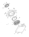
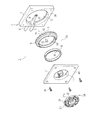
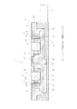
まず、図1はポンプ1を組立て状態で横断して示し、図2はポンプ1を分解状態で斜視して示し、図3はポンプ1を同じく分解状態で図2とは反対側から斜視して示している。
Hereinafter, a first example (first embodiment) of the present invention will be described with reference to FIGS.
First, FIG. 1 is a cross-sectional view of the
これらの図に示すように、ポンプ1のケーシケーシング2は、ケーシング主体3とケーシング蓋体4との組み合わせで構成される。これらケーシング主体3及びケーシング蓋体4は、ともに矩形状を成し、そのそれぞれ表面部(特には、この場合、外表面部)3a、4a以外の部分3b,4bを合成樹脂で形成している。そして、表面部3a,4aは、この場合、全部を金属で形成しており、その金属は、例えば金属テープの貼り付けで設けている。
As shown in these drawings, the
ここで、上記金属テープとしては、例えばアルミ箔テープ等を用いることが好ましい。又、ケーシング主体3及びケーシング蓋体4のそれぞれ表面部3a、4a以外の部分3b,4bを形成する合成樹脂としては、ABS(アクリロニトリル−ブタジエン−スチレンの共重合体)樹脂やPPS(ポリフェニレンサルファイド)樹脂等を用いることが好ましい。
Here, for example, an aluminum foil tape or the like is preferably used as the metal tape. Further, as the synthetic resin for forming the
ケーシング主体3には、ポンプ室5をケーシング蓋体4側に円形の凹陥部によって形成すると共に、そのポンプ室5に連通させて吸入口6及び吐出口7をともに外方へ突出するように形成している。又、ポンプ室5には、吸入口6と吐出口7との間を隔絶する凸部8を形成している。
In the casing
ポンプ室5の内部には、インペラ9を回転可能に配設している。このインペラ9は、軸方向の一方側の面であるケーシング主体3側の面9aに、ポンプ溝10を多数の放射状リブ11と交互に形成しており、従って、ケーシング主体3は、インペラ9が有するポンプ溝10側に位置し、ポンプ溝側ケーシングとなっている。これに対して、ケーシング蓋体4は、それとは反対側、すなわち、インペラ9の反ポンプ溝10側に位置し、反ポンプ溝側ケーシングとなっている。要するに、前記ケーシング2は、ポンプ溝側と反ポンプ溝側とに分割して形成しているのである。
An
インペラ9は、中心部に軸方向の両側に突出する軸12を有しており、これに対し、前記ケーシング主体3は、前記凸部8の端部に軸受部13を有していて、この軸受部13によって軸12の片側(ケーシング主体3側の部位)を支承するようにしている。
一方、インペラ9の軸方向の他方側の面であるケーシング蓋体4側には、円形の凹陥部14を形成しており、前記軸12の残る片側(ケーシング蓋体4側の部位)は、その凹陥部14の中心部に位置している。
The
On the other hand, a circular
上記凹陥部14の内周部には、外周に磁性リング15を一体的に有したリング状のロータマグネット16を装着している。ロータマグネット16は、磁極が周方向に多極となるように着磁している。
ケーシング蓋体4には、ケーシング主体3側とは反対側に円形の凹陥部17を形成し、ケーシング主体3側に上記凹陥部17を囲繞するリング状の凹陥部18を形成している。更に、上記凹陥部17の外底部(ケーシング主体3側)の中心部には軸受部19を形成しており、この軸受部19によって前記インペラ9の軸12の残る片側(ケーシング蓋体4側の部位)を支承するようにしている。
A ring-
In the
ケーシング蓋体4の凹陥部17には、ステータ20を装着している。このステータ20は、複数の磁極21aを有するステータコア21と、その各磁極21aに巻回されたステータコイル22とにより構成しており、ケーシング蓋体4をケーシング主体3に組み合わせることによって、前記ロータマグネット16がケーシング蓋体4のケーシング主体3側の凹陥部18内に位置し、上記ステータ20の各磁極21aの外周面が、ケーシング蓋体4のケーシング主体3側とは反対側の凹陥部17の周壁17aを間に挟んで、前記ロータマグネット16の内周面に径方向の内側より対向している。
A
かくして、インペラ9と、磁性リング15、及びロータマグネット16とでロータ23を構成し、このロータ23とステータ20とでモータ24を構成している。
なお、組み合わせたケーシング主体3とケーシング蓋体4は、複数のねじ25によって結合固定している。ポンプ1は、以上の構成である。
Thus, the
Note that the combined casing
図4は、以上のポンプ1を使用した冷却装置31を示している。この冷却装置31は、ポンプ1のほかに、受熱部32と、放熱部33とを有し、ポンプ1の前記吐出口7を連結パイプ34により受熱部32の入口部35に連結し、受熱部32の出口部36を連結パイプ37により放熱部33の入口部38に連結し、放熱部33の出口部39を連結パイプ40によりポンプ1の前記吸入口6に連結して、サイクル(循環路)41を組成している。
FIG. 4 shows a
次に、上記構成のものの作用を述べる。
まず、放熱部33には冷却用の流体(例えば液体)が注入されており、又、受熱部32は電気部品等の発熱部材に接触配置される。
この状態で、ポンプ1におけるモータ24のステータコイル22に通電すれば、インペラ9を含むロータ23が回転し、そのインペラ9の回転によるポンプ溝10の送液作用により、ポンプ1が、放熱部33内にある流体を、図4に矢印Aで示すように、連結パイプ40を通じて吸入口6からポンプ室5内に吸入し、吐出口7から連結パイプ34を通じて吐出する。
Next, the operation of the above configuration will be described.
First, a cooling fluid (for example, a liquid) is injected into the
In this state, if the
これによって、放熱部33内にある流体が、サイクル41で循環され、その過程で、電気部品等の発熱部材が発した熱が伝わった受熱部32を通ることにより、その熱を奪う。この熱を奪った流体は、次に放熱部33を通り、この放熱部33でその熱を放出される。かくして、流体が冷却され、この冷却された液体がその後ポンプ1により吸入されるものであり、これを繰り返して、上記電気部品等の発熱部材が冷却される。
As a result, the fluid in the
このように使用される状況にあって、ポンプ1は、ケーシング2の表面部以外の部分である、ケーシング主体3とケーシング蓋体4のそれぞれ表面部3a,4a以外の部分3b,4bを合成樹脂で形成しており、ケーシング2の表面部である、ケーシング主体3とケーシング蓋体4のそれぞれ表面部3a,4aは全部を金属で形成している。よって、流体の抜けは、その表面部3a,4aを形成した金属によって無くされるものであり、かくして、冷却装置31においては、サイクル41中の流体の量に不足を来たすことがなくなり、冷却性能の低下を回避することができる。従って、流体の補充をするメンテナンスも、無くすことができる。
In the situation where it is used in this way, the
又、ケーシング2のうち、モータ24のロータマグネット16とステータ20とに挟まれた部分(ケーシング蓋体4のケーシング主体3側とは反対側の凹陥部17の周壁17a)では、それが全部金属製であると、電磁誘導により大きな渦電流が生じ、モータ24の損失が大きくなるが、ケーシング2の表面部(ケーシング蓋体4の表面部4a)のみが金属で、それ以外の部分(4b)は合成樹脂であることにより、生じる渦電流が小さくなり、モータ24の損失を少なくできる。
Further, in the portion of the
なお、ケーシング2の表面部はその全部を金属で形成するものに限られず、一部を金属で形成しても、その部分で流体の抜けを防止できるから、流体の抜けを少なくできて、冷却装置31においては、サイクル41中の流体の量に早期の不足を来たすことがなくなり、冷却性能の低下を極力回避することができる。従って、流体の補充をするメンテナンスも、その実行回数を少なくすることができる。又、その場合、金属で形成する表面部の一部が、モータ24のロータマグネット16とステータ20とにより挟まれる部分の表面部を含むことにより、生じる渦電流を小さくでき、モータ24の損失を少なくできる。
Note that the entire surface portion of the
加えて、本構成のものにおいては、ケーシング2の表面部の金属を、金属テープの貼り付けで設けており、その実現が容易にできる。
このケーシング2の表面部の金属は、金属メッキで設けても良い。又、その表面部以外の部分を合成樹脂で成形する型の内部に、表面部となる金属板をあらかじめセットしておいて、そこに合成樹脂の溶湯を注入して表面部以外の部分を成形することにより、それと上述の表面部となる金属板とを一体化するインサート成形で設けても良い。これらによっても、ケーシング2の表面部を金属とする構成の実現が容易にできる。
In addition, in the thing of this structure, the metal of the surface part of the
The metal of the surface portion of the
以上に対して、図5及び図6は本発明の第2実施例(第2の実施形態)を示すもので、第1実施例と同一の部分には同一の符号を付して説明を省略し、異なる部分についてのみ述べる。 5 and 6 show the second embodiment (second embodiment) of the present invention. The same parts as those in the first embodiment are denoted by the same reference numerals and the description thereof is omitted. Only the different parts will be described.
このものの場合、まず、図5に示すように、ポンプ1のポンプ溝側のケーシングであるケーシング主体51の全部を金属、特には熱伝導率が150〔W/(mk)〕以上の金属で形成しており、反ポンプ溝側のケーシングであるケーシング蓋体4の表面部4a以外の部分4bを合成樹脂で形成し、このケーシング蓋体4の表面部4aの全部、又は該ケーシング蓋体4の前記ステータ20とロータマグネット16とにより挟まれる部分の表面部を含む表面部4aの一部(図示例は全部)を金属で形成している。この表面部の金属は、前述同様の、金属テープの貼り付け、又は金属メッキ、もしくはインサート成形によるものである。
In this case, first, as shown in FIG. 5, the entire casing
このものでは、ケーシング主体51(ポンプ溝側のケーシング)を形成した金属と、ケーシング蓋体4(反ポンプ溝側のケーシング)の表面部4aの全部又は一部を形成した金属とで、流体の抜けが無くされ、又は少なくされる。
又、この場合も、反ポンプ溝側であって且つ一部がモータ24のステータ20とロータマグネット16とにより挟まれる側のケーシング蓋体4の表面部4aの全部、又は該ケーシング蓋体4の上記ステータ20とロータマグネット16とにより挟まれる部分の表面部を含む表面部4aの一部を金属で形成し、それ以外は合成樹脂で形成していることにより、モータ24の電磁誘導で生じる渦電流が小さくなり、モータの損失を少なくできる。
In this case, the metal that forms the casing main body 51 (the casing on the pump groove side) and the metal that forms all or part of the
Also in this case, the
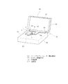
そして、このポンプ1は、図6に示すように、電気機器、中でもパーソナルコンピュータ52に使用している。詳細には、パーソナルコンピュータ52の本体部53がキーボード(図示省略)を具え、本体部53に開閉回動可能に設けられた蓋部54が液晶による表示部(これも図示省略)を具えた一般的構成に対し、その本体部53の内部(キーボードの下側)に設けられた発熱部材としてのCPU55に、ポンプ1の上記金属製のケーシング本体51を密接させており、すなわち、その金属製のケーシング本体51をCPU55が発する熱を受ける受熱部として機能させるようにしている。
As shown in FIG. 6, the
そして、冷却装置56としては、ポンプ1のほかに、放熱部57を有し、この放熱部57を、蓋部54の内部(表示部の裏側)に設けていて、これの入口部58と上記ポンプ1の吐出口7とを連結パイプ59により接続し、放熱部57の出口部60とポンプ1の吸入口6とを連結パイプ61により接続している。
従って、この構成でも、ポンプ1を作動させれば、放熱部57内に入れられた流体(この場合も、例えば液体)が、連結パイプ61を通じてポンプ1の吸入口6からポンプ室5内に吸入され、吐出口7から連結パイプ59を通じて吐出されることにより、放熱部57内の流体が循環され、その過程で、CPU55が発した熱をポンプ1のケーシング主体51(受熱部)を介して奪う。
In addition to the
Therefore, even in this configuration, when the
又、このとき、放熱部57では、そこを通る液体が冷却され、この冷却された液体が前記ポンプ1により吸入されるものであり、これを繰り返して、上記CPU55が冷却される。
このものによれば、ポンプ1の、金属で形成したポンプ溝側のケーシング(ケーシング主体51)で、CPU55(発熱部材)が発した熱を奪うことで、その熱をインペラ9のポンプ溝10で運ばれる流体に直接的に与えることができるので、冷却性能を効率良く得ることができる。
At this time, in the
According to this, the heat generated by the CPU 55 (heating member) is taken away by the pump groove casing (casing main body 51) formed of metal of the
又、電気機器としても、ポンプ1を使用していることにより、ケーシング2からの流体の抜けが無く又は少なく、更にモータ24の損失も少なくして、発熱部材の冷却ができる。
なお、ポンプ1をパーソナルコンピュータ52を初めとした電気機器に使用するにも、受熱部は、ポンプ1とは別体で具えていても良い。
In addition, since the
Even when the
又、ポンプ1の、金属で全部又は一部を形成するケーシング2の表面部としては、外表面部に限られず、内表面部(ポンプ室5側)であっても良く、その両方であっても良い。
このほか、本発明は上記し且つ図面に示した実施例にのみ限定されるものではなく、要旨を逸脱しない範囲内で適宜変更して実施し得る。
Further, the surface portion of the
In addition, the present invention is not limited to the embodiments described above and shown in the drawings, and can be implemented with appropriate modifications without departing from the scope of the invention.
図面中、1はポンプ、2はケーシング、3はケーシング主体(ポンプ溝側ケーシング)、3aは表面部、3bは表面部以外の部分、4はケーシング蓋体(反ポンプ溝側ケーシング)、4aは表面部、4bは表面部以外の部分、5はポンプ室、9はインペラ、10はポンプ溝、16はロータマグネット、20はステータ、23はロータ、24はモータ、51はケーシング主体(ポンプ溝側ケーシング)、52はパーソナルコンピュータ(電気機器)、55はCPU(発熱部材)、56は冷却装置、57は放熱部を示す。
In the drawings, 1 is a pump, 2 is a casing, 3 is a casing main body (pump groove side casing), 3a is a surface portion, 3b is a portion other than the surface portion, 4 is a casing lid (anti-pump groove side casing), 4a is Surface portion, 4b is a portion other than the surface portion, 5 is a pump chamber, 9 is an impeller, 10 is a pump groove, 16 is a rotor magnet, 20 is a stator, 23 is a rotor, 24 is a motor, 51 is a casing main body (on the pump groove side) Casing), 52 is a personal computer (electrical device), 55 is a CPU (heat generating member), 56 is a cooling device, and 57 is a heat radiating section.
Claims (7)
前記ポンプ室に回転可能に配設され、回転されることによって、流体を前記吸入口からポンプ室内に吸入して前記吐出口から吐出するインペラと、
このインペラに一体的に設けたロータマグネット、並びにこのロータマグネットと前記ケーシングの一部を挟んで対向するように設けたステータを有して成るモータとを具備し、
前記ケーシングの表面部の全部、又は前記モータのステータとロータマグネットとにより挟まれる部分の表面部を含む前記ケーシングの表面部の一部を金属で形成し、それ以外の部分を合成樹脂で形成したことを特徴とするポンプ。 A casing having a pump chamber therein and a suction port and a discharge port respectively communicating with the pump chamber;
An impeller that is rotatably arranged in the pump chamber and rotates to suck fluid from the suction port into the pump chamber and discharge the fluid from the discharge port;
A rotor magnet provided integrally with the impeller, and a motor having a stator provided so as to face the rotor magnet with a part of the casing interposed therebetween,
A part of the surface portion of the casing including the entire surface portion of the casing or the surface portion of the portion sandwiched between the stator and rotor magnet of the motor is formed of metal, and the other portions are formed of synthetic resin. A pump characterized by that.
前記ポンプ室に回転可能に配設され、回転されることによって、流体を前記吸入口からポンプ室内に吸入して前記吐出口から吐出するインペラと、
このインペラに一体的に設けたロータマグネット、並びにこのロータマグネットと前記ケーシングの一部を挟んで対向するように設けたステータを有して成るモータとを具備し、
前記ケーシングを、インペラが有するポンプ溝側と反ポンプ溝側とに分割して形成し、そのポンプ溝側のケーシングを金属で形成し、反ポンプ溝側であって且つ一部が前記モータのステータとロータマグネットとにより挟まれる側のケーシングの表面部の全部、又は該ケーシングの前記ステータとロータマグネットとにより挟まれる部分の表面部を含む表面部の一部を金属で形成し、それ以外の部分を合成樹脂で形成したことを特徴とするポンプ。 A casing having a pump chamber therein and a suction port and a discharge port respectively communicating with the pump chamber;
An impeller that is rotatably arranged in the pump chamber and rotates to suck fluid from the suction port into the pump chamber and discharge the fluid from the discharge port;
A rotor magnet provided integrally with the impeller, and a motor having a stator provided so as to face the rotor magnet with a part of the casing interposed therebetween,
The casing is divided into a pump groove side and an anti-pump groove side of the impeller, and the casing on the pump groove side is made of metal, and the stator of the motor is partly on the anti-pump groove side. All of the surface portion of the casing sandwiched between the rotor and the magnet, or a part of the surface portion including the surface portion of the casing sandwiched between the stator and the rotor magnet is made of metal, and the other portions A pump characterized by being made of synthetic resin.
このポンプが吐出する流体を通して放熱する放熱部とを具備し、
前記ポンプのポンプ溝側のケーシングを発熱部材に接触させることにより、ポンプを通る流体が、前記ポンプ溝側のケーシングを介し、前記発熱部材が発する熱を奪うことを特徴とする冷却装置。 A pump according to claim 2;
A heat dissipating part that dissipates heat through the fluid discharged by the pump;
The cooling device according to claim 1, wherein the pump groove side casing of the pump is brought into contact with the heat generating member so that the fluid passing through the pump takes heat generated by the heat generating member through the pump groove side casing.
このポンプが吐出する流体で熱が奪われる発熱部材を具えると共に、
その発熱部材から奪った熱を放出する放熱部を具えることを特徴とする電気機器。
A pump according to any of claims 1 to 5,
In addition to having a heat generating member whose heat is taken away by the fluid discharged from this pump,
An electric device comprising a heat radiating portion that releases heat taken from the heat generating member.
Priority Applications (1)
| Application Number | Priority Date | Filing Date | Title |
|---|---|---|---|
| JP2004107157A JP2005291084A (en) | 2004-03-31 | 2004-03-31 | Pump, cooling device and electrical equipment |
Applications Claiming Priority (1)
| Application Number | Priority Date | Filing Date | Title |
|---|---|---|---|
| JP2004107157A JP2005291084A (en) | 2004-03-31 | 2004-03-31 | Pump, cooling device and electrical equipment |
Publications (1)
| Publication Number | Publication Date |
|---|---|
| JP2005291084A true JP2005291084A (en) | 2005-10-20 |
Family
ID=35324301
Family Applications (1)
| Application Number | Title | Priority Date | Filing Date |
|---|---|---|---|
| JP2004107157A Pending JP2005291084A (en) | 2004-03-31 | 2004-03-31 | Pump, cooling device and electrical equipment |
Country Status (1)
| Country | Link |
|---|---|
| JP (1) | JP2005291084A (en) |
Cited By (3)
| Publication number | Priority date | Publication date | Assignee | Title |
|---|---|---|---|---|
| JP2006063962A (en) * | 2004-08-30 | 2006-03-09 | Toshiba Corp | Cooling fluid pump, cooling device and electrical equipment |
| CN110360125A (en) * | 2019-07-01 | 2019-10-22 | 深圳兴奇宏科技有限公司 | Slim pump configuration |
| US11239721B2 (en) | 2019-03-12 | 2022-02-01 | Kabushiki Kaisha Toshiba | Electric rotating machine, electric rotating machine system, vehicle, power generator, lifting device, and robot |
-
2004
- 2004-03-31 JP JP2004107157A patent/JP2005291084A/en active Pending
Cited By (3)
| Publication number | Priority date | Publication date | Assignee | Title |
|---|---|---|---|---|
| JP2006063962A (en) * | 2004-08-30 | 2006-03-09 | Toshiba Corp | Cooling fluid pump, cooling device and electrical equipment |
| US11239721B2 (en) | 2019-03-12 | 2022-02-01 | Kabushiki Kaisha Toshiba | Electric rotating machine, electric rotating machine system, vehicle, power generator, lifting device, and robot |
| CN110360125A (en) * | 2019-07-01 | 2019-10-22 | 深圳兴奇宏科技有限公司 | Slim pump configuration |
Similar Documents
| Publication | Publication Date | Title |
|---|---|---|
| CN100529411C (en) | Cooling pump, electric device and personnel computer | |
| TWI413348B (en) | Brushless fan motor | |
| CN110173434B (en) | Motor pump | |
| WO2018018905A1 (en) | External rotor motor | |
| JP2006101672A (en) | Rotating electric machine with built-in fluid flow path | |
| CN103765732A (en) | Electric motor | |
| CN112262262B (en) | Electric coolant pump | |
| JP2017048768A (en) | Canned motor pump | |
| JP2006200427A (en) | pump | |
| CN101312640A (en) | heat sink | |
| JP2011234433A (en) | Cooling structure of motor | |
| JP2004183595A (en) | Electric brushless water pump | |
| JP2005317797A (en) | Pumps, electronics and cooling devices | |
| JP2005294519A (en) | Pump, cooling device, electrical equipment and personal computer | |
| JP2001078390A (en) | Rotating electric machine | |
| CN219124032U (en) | Heat radiation structure and brushless motor using same | |
| JP2022080618A (en) | Wireless power supply device and wireless power supply unit with cooling function | |
| JP2005291084A (en) | Pump, cooling device and electrical equipment | |
| JP4653444B2 (en) | Cooling fluid pump, cooling device and electrical equipment | |
| JP2004159402A (en) | Motors and motor generators | |
| US10550851B2 (en) | Fan having an impeller including a resin portion and a metal plate | |
| JP5823358B2 (en) | Electric compressor | |
| JP4134884B2 (en) | Cooling system | |
| JP2024112140A (en) | Motor | |
| JP2005330877A (en) | Canned motor pump |