JP2005291070A - Control device for gas turbine engine - Google Patents
Control device for gas turbine engine Download PDFInfo
- Publication number
- JP2005291070A JP2005291070A JP2004106422A JP2004106422A JP2005291070A JP 2005291070 A JP2005291070 A JP 2005291070A JP 2004106422 A JP2004106422 A JP 2004106422A JP 2004106422 A JP2004106422 A JP 2004106422A JP 2005291070 A JP2005291070 A JP 2005291070A
- Authority
- JP
- Japan
- Prior art keywords
- sensor
- output
- value
- engine
- control
- Prior art date
- Legal status (The legal status is an assumption and is not a legal conclusion. Google has not performed a legal analysis and makes no representation as to the accuracy of the status listed.)
- Granted
Links
Images


Classifications
-
- F—MECHANICAL ENGINEERING; LIGHTING; HEATING; WEAPONS; BLASTING
- F02—COMBUSTION ENGINES; HOT-GAS OR COMBUSTION-PRODUCT ENGINE PLANTS
- F02C—GAS-TURBINE PLANTS; AIR INTAKES FOR JET-PROPULSION PLANTS; CONTROLLING FUEL SUPPLY IN AIR-BREATHING JET-PROPULSION PLANTS
- F02C9/00—Controlling gas-turbine plants; Controlling fuel supply in air- breathing jet-propulsion plants
- F02C9/26—Control of fuel supply
- F02C9/28—Regulating systems responsive to plant or ambient parameters, e.g. temperature, pressure, rotor speed
-
- F—MECHANICAL ENGINEERING; LIGHTING; HEATING; WEAPONS; BLASTING
- F02—COMBUSTION ENGINES; HOT-GAS OR COMBUSTION-PRODUCT ENGINE PLANTS
- F02C—GAS-TURBINE PLANTS; AIR INTAKES FOR JET-PROPULSION PLANTS; CONTROLLING FUEL SUPPLY IN AIR-BREATHING JET-PROPULSION PLANTS
- F02C9/00—Controlling gas-turbine plants; Controlling fuel supply in air- breathing jet-propulsion plants
- F02C9/26—Control of fuel supply
-
- F—MECHANICAL ENGINEERING; LIGHTING; HEATING; WEAPONS; BLASTING
- F05—INDEXING SCHEMES RELATING TO ENGINES OR PUMPS IN VARIOUS SUBCLASSES OF CLASSES F01-F04
- F05D—INDEXING SCHEME FOR ASPECTS RELATING TO NON-POSITIVE-DISPLACEMENT MACHINES OR ENGINES, GAS-TURBINES OR JET-PROPULSION PLANTS
- F05D2270/00—Control
- F05D2270/01—Purpose of the control system
- F05D2270/07—Purpose of the control system to improve fuel economy
Abstract
Description
この発明は、ガスタービン・エンジンの制御装置、より具体的には航空機用ガスタービン・エンジンの制御装置に関する。 The present invention relates to a control device for a gas turbine engine, and more particularly to a control device for an aircraft gas turbine engine.
ガスタービン・エンジンの制御においては、エンジンに配置されたセンサの出力から運転状態を検出し、それに基づいて供給すべき燃料量を算出するなど種々の制御が行われる。そのセンサの出力の適否の判断に関し、下記の特許文献1に記載されるように、センサ出力が許容範囲内にあるか否か判断し、許容範囲内にないと判断される度に、ずれ方向に応じて許容範囲の上下限を設定し直し、次回の入力値が設定し直された許容範囲内において上下に触れた回数を所定時間内においてカウントし、そのカウント値が所定値を超えるとき、異常が発生したと判定する技術が提案されている。
ガスタービン・エンジン、特に航空機用ガスタービン・エンジンにあっては同種のセンサを複数個設け、その中のいずれかの値を選択するなどして制御が行われるが、特許文献1に記載した従来技術は、あるセンサ出力の許容範囲での振れに基づいてその異常を判定しているに止まり、同種のセンサの中から適正な値を選択する点は開示するものではなかった。 In a gas turbine engine, particularly an aircraft gas turbine engine, control is performed by providing a plurality of sensors of the same type and selecting one of the sensors. The technology only determines the abnormality based on the fluctuation of a certain sensor output within an allowable range, and does not disclose that an appropriate value is selected from the same type of sensors.
従って、この発明の目的は上記した課題を解消することにあり、同種のセンサが複数個設けられるとき、その中から燃料供給制御などに使用可能なセンサ出力を的確に選択して制御精度を向上させるようにしたガスタービン・エンジンの制御装置を提供することにある。 Accordingly, an object of the present invention is to solve the above-described problems. When a plurality of sensors of the same type are provided, the sensor output that can be used for fuel supply control or the like is accurately selected from these to improve the control accuracy. An object of the present invention is to provide a control device for a gas turbine engine.
上記の目的を達成するために、請求項1にあっては、少なくとも1基のタービンを備えたガスタービン・エンジンにおいて、前記タービンの回転数を示す出力を生じる、少なくとも2個のタービン回転数センサ、少なくとも前記センサから出力された値を入力し、少なくとも入力された値に基づいて前記エンジンへの燃料供給を制御する第1の制御系、および少なくとも前記センサと同一のセンサを備えると共に、前記同一のセンサから出力された値を入力し、前記第1の制御系に異常が生じたとき、前記第1の制御系に代わって少なくとも入力された値に基づいて前記エンジンへの燃料供給を制御する第2の制御系を備えたガスタービン・エンジンの制御装置において、前記第1、第2の制御系が、前記少なくとも2個のタービン回転数センサから出力される少なくとも4個の値を入力し、その中の少なくとも3個の値が同一と許容できる範囲内にあるか否か判断する3値比較手段、および前記少なくとも3値がそれぞれ残りの少なくとも1個の値と同一と許容できる範囲内にあるか否か判断して前記燃料供給制御に使用可能なセンサ出力か否か判定する4値比較手段を備える如く構成した。
To achieve the above object, according to
請求項2に係るガスタービン・エンジンの制御装置にあっては、前記3値比較手段および4値比較手段は、前記燃料制御に使用不可能なセンサ出力も判定する如く構成した。 In the control apparatus for a gas turbine engine according to claim 2, the ternary value comparing means and the quaternary value comparing means are configured to determine a sensor output that cannot be used for the fuel control.
請求項3に係るガスタービン・エンジンの制御装置にあっては、さらに、前記タービンから排出される燃焼ガスの温度を示す出力を生じる、少なくとも1個の温度センサ、少なくとも前記タービン回転数センサおよび温度センサから出力された値を入力し、所定時間ごとに前記出力された値の変化率あるいは差をそれぞれ対応する所定のしきい値と比較し、比較結果に基づいて前記エンジンが定常状態と過渡状態のいずれにあるか判定する運転状態判定手段、および前記判定された運転状態に応じて前記許容できる範囲を変更する許容範囲変更手段、を備える如く構成した。 The control device for a gas turbine engine according to claim 3, further comprising at least one temperature sensor, at least the turbine rotational speed sensor, and a temperature for generating an output indicating a temperature of combustion gas discharged from the turbine. The value output from the sensor is input, and the rate of change or difference of the output value is compared with a corresponding predetermined threshold value every predetermined time. Based on the comparison result, the engine is in a steady state and a transient state. The operating state determining means for determining which of the above is acceptable, and the allowable range changing means for changing the allowable range in accordance with the determined operating state.
請求項1にあっては、エンジンへの燃料供給を制御する第1、第2の制御系が少なくとも2個のタービン回転数センサから出力される少なくとも4個の値を入力し、その中の少なくとも3個の値が同一と許容できる範囲内にあるか否か判断し、少なくとも3値がそれぞれ残りの少なくとも1個の値と同一と許容できる範囲内にあるか否か判断して燃料供給制御に使用可能なセンサ出力か否か判定する如く構成したので、同種のセンサが複数個設けられるときも、その中から燃料供給制御などに使用可能なセンサ出力を的確に選択することができ、制御精度を向上させることができる。
In
請求項2に係るガスタービン・エンジンの制御装置にあっては、制御に使用不可能なセンサ出力も判定する如く構成したので、前記した効果に加え、そのような異常な信号を制御に使用されるのを回避することができ、よって制御精度を一層向上させることができる。 The gas turbine engine control apparatus according to claim 2 is configured to determine sensor outputs that cannot be used for control. In addition to the effects described above, such an abnormal signal is used for control. Therefore, the control accuracy can be further improved.
請求項3に係るガスタービン・エンジンの制御装置にあっては、さらに、タービンから排出される燃焼ガスの温度を示す出力を生じる、少なくとも1個の温度センサを備えると共に、タービン回転数センサおよび温度センサから出力された値を入力し、所定時間ごとに出力された値の変化率あるいは差をそれぞれ対応する所定のしきい値と比較し、比較結果に基づいてエンジンが定常状態と過渡状態のいずれにあるか判定し、判定された運転状態に応じて許容できる範囲を変更する如く構成したので、燃料供給制御などに使用可能なセンサ出力を一層的確に選択することができ、制御精度を一層向上させることができる。 The control device for a gas turbine engine according to claim 3, further comprising at least one temperature sensor for generating an output indicating the temperature of the combustion gas discharged from the turbine, and the turbine rotational speed sensor and the temperature. The value output from the sensor is input, and the rate of change or difference of the value output every predetermined time is compared with the corresponding predetermined threshold value. Based on the comparison result, the engine is in either steady state or transient state. The sensor output that can be used for fuel supply control, etc. can be selected more accurately, and the control accuracy is further improved because the allowable range is changed according to the determined operating state. Can be made.
以下、添付図面に即してこの発明に係るガスタービン・エンジンの制御装置を実施するための最良の形態について説明する。 The best mode for carrying out a gas turbine engine control apparatus according to the present invention will be described below with reference to the accompanying drawings.
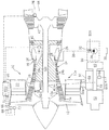
図1は、そのガスタービン・エンジンの制御装置を全体的に示す概略図である。 FIG. 1 is a schematic diagram showing the overall control apparatus for the gas turbine engine.
尚、ガスタービン・エンジンとして、航空機用ガスタービン・エンジンを例にとる。また、航空機用ガスタービン・エンジンとしては、ターボジェット・エンジン、ターボファン・エンジン、ターボプロップ・エンジンおよびターボシャフト・エンジンの4種が知られているが、以下、2軸のターボファン・エンジンを例にとって説明する。 Note that an aircraft gas turbine engine is taken as an example of the gas turbine engine. There are four known types of aircraft gas turbine engines: turbojet engines, turbofan engines, turboprop engines, and turboshaft engines. Let's take an example.
図1において、符号10はターボファン・エンジン(ガスタービン・エンジン。以下「エンジン」という)を示し、符号10aはエンジン本体を示す。エンジン10は機体(図示せず)の適宜位置にマウントされる。
In FIG. 1,
エンジン10はファン(ファン動翼)12を備え、ファン12は高速で回転しつつ外気から空気を吸引する。ファン12にはロータ12aが一体的に形成され、ロータ12aは対向して配置されたステータ14と共に低圧圧縮機(コンプレッサ)16を構成し、そこで吸引した空気を圧縮しつつ後方に圧送する。
The
尚、ファン12の付近にはセパレータ20によってダクト(バイパス)22が形成され、吸引された空気の大部分は後段(コア側)で燃焼させられることなく、ダクト22を通ってエンジン後方に噴出させられる。ファン排気は、その反作用としてエンジン10が搭載される機体(図示せず)に推力(スラスト)を生じさせる。推力の大部分は、このファン排気によって生じる。
A duct (bypass) 22 is formed in the vicinity of the
低圧圧縮機16で圧縮された空気は後段の高圧圧縮機24に送られ、そこでロータ24aおよびステータ24bによってさらに圧縮された後、後段の燃焼器26に送られる。
The air compressed by the low-
燃焼器26は燃料ノズル28を備え、燃料ノズル28にはFCU(Fuel Control Unit 。燃料制御ユニットあるいは燃料制御部)30で調量された燃料が圧送される。即ち、FCU30は燃料調量バルブ32を備え、燃料ポンプ(ギヤポンプ)34によって機体の適宜位置に配置された燃料タンク36から汲み上げられた燃料は、燃料調量バルブ32で調量された後、燃料供給通路38を通って燃料ノズル28に供給される。
The
噴霧された燃料は高圧圧縮機24から圧送された圧縮空気と混合し、エンジン始動時にエキサイタ(図1で図示省略)および点火プラグ(図示せず)で点火されて燃焼する。混合気は一度着火されて燃焼を開始すると、かかる圧縮空気と燃料からなる混合気を連続的に供給されて燃焼を継続する。
The sprayed fuel is mixed with the compressed air pumped from the high-
燃焼によって生じた高温高圧ガスは高圧タービン40に送られ、高圧タービン40を高速回転させる。高圧タービン40は前記した高圧圧縮機のロータ24aに高圧タービン軸40aを介して接続され、前記ロータ24aを回転させる。
The high-temperature high-pressure gas generated by the combustion is sent to the high-
高温高圧ガスは、高圧タービン40を回転駆動した後、低圧タービン42に送られ、低圧タービン42を比較的低速で回転させる。低圧タービン42は前記した低圧圧縮機16のロータ12aに低圧タービン軸42a(軸40aと同心二軸構造)を介して接続されており、前記ロータ12aおよびファン12を回転させる。
The high-temperature high-pressure gas rotates the high-
低圧タービン42を通過した高温高圧ガス(タービン排気)は、ダクト22を通ってそのまま排出されるファン排気と混合させられてジェットノズル44からエンジン後方に噴出される。
The high-temperature high-pressure gas (turbine exhaust) that has passed through the low-
エンジン本体10aの外部下面の前側寄りには、アクセサリ・ドライブ・ギアボックス(以下「ギアボックス」という)50がステー50aを介して取り付けられると共に、ギアボックス50の前端には一体的に構成されたスタータおよびジェネレータ(以下「スタータ」と総称する)52が取り付けられる。尚、ギアボックス50の後端には前記したFCU30が配置される。
An accessory drive gearbox (hereinafter referred to as “gearbox”) 50 is attached via a
エンジン10の始動時、スタータ52によって軸56が回転させられると、その回転は駆動軸58(および図示しないベベルギアなどのギア機構)を介して高圧タービン軸40aに伝えられ、燃焼に必要な空気が送り込まれる。
When the
他方、軸56の回転はPMA(パーマネントマグネット・オルタネータ)60と高圧(燃料)ポンプ34に伝えられて高圧(燃料)ポンプ34を駆動し、前記したように燃料を燃料ノズル28を介して噴霧する。よって生じた混合気は、点火されて燃焼を開始する。
On the other hand, the rotation of the
エンジン10が自立運転回転数に達すると、高圧タービン軸40aの回転が逆に駆動軸58(および図示しないベベルギアなどのギア機構)を介して軸56に伝えられ、燃料ポンプ34を駆動すると共に、PMA60とスタータ52を駆動する。それによって、PMA60は発電すると共に、スタータ52は、機体に電力を供給する。
When the
エンジン10において、低圧タービン軸42aの付近にはN1センサ(回転数センサ)62が配置され、低圧タービン回転数(低圧タービン軸42aの回転数)N1に比例する信号を出力すると共に、軸56の付近にはN2センサ(回転数センサ)64が配置され、高圧タービン回転数(高圧タービン軸40aの回転数)N2に比例する信号を出力する。
In the
またエンジン本体10aの前面の空気取り入れ口66の付近にはT1センサ(温度センサ)68およびP1センサ(圧力センサ)70が配置され、流入空気の温度T1および圧力P1に比例する信号を出力すると共に、後述するECU(Electronic Control Unit 。電子制御ユニット)の内部にはP0センサ(圧力センサ)72が設けられ、大気圧P0に比例する信号を出力する。また、ECUの内部には温度センサ(図示せず)が設けられ、その部位の温度に応じた信号を出力する。
In addition, a T1 sensor (temperature sensor) 68 and a P1 sensor (pressure sensor) 70 are disposed in the vicinity of the
またロータ24aの下流にはP3センサ(圧力センサ)74が配置されて高圧圧縮機24の出力圧P3に比例する信号を出力すると共に、低圧タービン42の下流の適宜位置にはEGTセンサ(温度センサ)76が配置され、排ガス温度EGT(低圧タービン42から排出される排ガスの温度)に比例する信号を出力する。
A P3 sensor (pressure sensor) 74 is disposed downstream of the
エンジン本体10aの上端位置には前記したECU(符号80で示す)が収納される。上記したエンジン10の運転状態を示すセンサ群の出力は、ECU80に送られる。
The above-described ECU (indicated by reference numeral 80) is accommodated at the upper end position of the
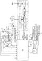
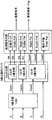
図2は、ECU80および前記したFCU30の構成、特にFCU30の構成を全体的に示すブロック図である。
FIG. 2 is a block diagram generally showing the configuration of the
前記したセンサ群に加え、機体操縦席(コックピット。図示せず)付近に設置されたスラストレバー(スロットルレバー)82の付近にはTLAセンサ(スラストレバー角度センサ)84が配置され、パイロット(操縦者)が入力したスラストレバー角度あるいは位置(操作者要求推力)TLAに比例する信号を出力する。TLAセンサ84の出力もECU80に入力される。尚、図2(および後述する図3)において各センサ(P0センサ、TLAセンサなど)は、その検出対象パラメータ名(P0、TLAなど)で示す。
In addition to the sensor group described above, a TLA sensor (thrust lever angle sensor) 84 is disposed in the vicinity of a thrust lever (throttle lever) 82 installed in the vicinity of the aircraft operator's seat (cockpit, not shown). A signal proportional to the thrust lever angle or position (operator request thrust) TLA input is output. The output of the
さらに、FCU30の適宜位置にはFMVPセンサ(バルブ位置センサ。図2で図示省略)が設けられ、燃料調量バルブ32のバルブ位置FMVPに比例する信号を出力する。FMVPセンサの出力もECU80に入力される。
Further, an FMVP sensor (valve position sensor; not shown in FIG. 2) is provided at an appropriate position of the
さらに、ECU80には、CAN(通信)インターフェース・ユニット88を介して前記したスラストレバー82以外の機器のパイロット選択指令90、機体搭載コンピュータ(Air Data Computer あるいはADC)92からのデータ(例えばマッハ数Mn、圧力高度ALT、外気温度(より具体的には全温度TAT、真大気温度SAT))、および第2のエンジン(図示せず)のECU94からのデータが入力(あるいは出力)されると共に、コックピット内のディスプレイ96に接続されてECU80のデータを表示させる。
Further, the
ECU80は10msecごとに起動され、入力値に基づき、後述する如く過渡・定常の運転状態判定およびセンサ出力の可否判定を行うと共に、40msecごとに、スラストレバー角度(操作者要求出力)TLAに応じて低圧タービン軸回転数(低圧タービン回転数)N1と目標回転数N1comの偏差が減少するように、エンジン10に供給すべき燃料量(燃料流量)の指令値(操作量)Wfを、トルクモータ98への通電電流指令値として算出してFCU30に送る。
The
さらに、ECU80は検出された低圧タービン回転数N1および高圧タービン回転数N2の値のいずれかがリミット値(例えば、それぞれの最高回転数の107%相当値)を超えるか否か監視し、検出された低圧タービン回転数N1および高圧タービン回転数N2のいずれかがリミット値を超えるときはオーバースピードと判断し、エンジン10に供給すべき燃料流量が所定値、より具体的には零あるいは最小となるようにトルクモータ98への通電電流指令値を決定してFCU30に送る。
Further, the
さらに、ECU80は検出された高圧タービン回転数N2の変化率N2ドット(N2の微分値。加減速率)と目標加減速率N2ドットcomの偏差が減少するようにエンジン10に供給すべき燃料流量の指令値Wf、より詳しくはトルクモータ98への通電電流指令値を決定してFCU30に送る。
Further, the
FCU30は低圧(燃料)ポンプ100を備え、燃料タンク36(図2で図示省略)から汲み上げられた燃料は、フィルタ(およびオイルクーラ)102を経て前記した高圧(燃料)ポンプ34で高圧化されて燃料調量バルブ32に送られる。トルクモータ98は燃料調量バルブ32に接続され、そのスプール位置を決定する。従って、高圧ポンプ34を介して圧送された燃料は、燃料調量バルブ32でそのスプール位置に応じた流量に調節(調量)される。調量された燃料は、シャットオフバルブ104、ドレーンバルブ106およびシャットオフ機構108を介して前記した燃料ノズル28に供給される。このように、ECU80は、40msecごとにエンジン10に供給すべき燃料流量の指令値Wfを算出し、それに応じてFCU30で算出された燃料流量となるように燃料供給が制御される。
The
尚、低圧タービン軸42aには非常停止スイッチ110が接続されており、低圧タービン軸42aが何らかの理由から変位するとオンし、シャットオフ機構108を動作させて燃料ノズル28への燃料供給を機械的に遮断する。同様に、ソレノイド112が設けられ、パイロット選択指令90に応じてシャットオフバルブ104を動作させて燃料ノズル28への燃料供給を遮断する。
An
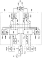
図3は、上記したECU80およびFCU30の構成をハードウェアで示すブロック図である。
FIG. 3 is a block diagram showing the configuration of the
エンジン10が航空機用ガスタービン・エンジンであることから、ECU80およびFCU30はプライマリレーン(Primary Lane。第1の制御系)200とセカンダリレーン(Secondary Lane。第2の制御系)202からなり、それぞれ上記した動作を行うCPU200a,202a、その動作をモニタするモニタCPU200b,202bと、さらにモニタCPUの動作を監視するWDT(ウォッチドグタイマ)200c,202cとを備える。モニタ結果からレーン200に異常が生じたと判断される場合、レーン202がレーン200に代わって燃料供給制御を実行する。
Since the
2個のCPU200aと202aが上記したECU80およびFCU30として動作し、図示のセンサ出力に基づいてトルクモータ98への通電指令値を算出し、サーボドライバ200d,202d(図2で図示省略)を介してトルクモータ98に出力する(サーボドライバ200d,202dの動作はモニタ(回路)200e,202eでモニタされる)。図3から明らかな如く、トルクモータ98も実際には、プライマリレーン用の981とセカンダリレーン用の982の2個が設けられる。尚、プライマリレーンのCPU200aが正常に動作している限り、プライマリレーンの出力のみがトルクモータ981に送られる。
Two
同様に、上記した種々のセンサの多くも、実際には、2個以上設けられる。TLAセンサ84は、図示の如く、3個設けられ、その出力が2つのレーン200,202に入力される。N1センサ62、EGTセンサ76およびFMVPセンサ(図2で図示省略)は2個設けられ、それぞれ2つのレーン200,202に入力される。さらに、N2センサ64は両レーン用に2個(A,Bで示す)、合計4個設けられ、その中のA,B2個のセンサ出力が2つのレーン200,202に入力される。
Similarly, many of the various sensors described above are actually provided in two or more. As shown in the figure, three
N2センサ64は具体的には磁気ピックアップからなり、同種の構造のものが軸56の付近に4個配置されてなる。N1センサ62も同様の構造の磁気ピックアップが低圧タービン軸42aの付近に2個配置されてなる。他のセンサについても同様に、同種構造のものが該当個数だけ配置される。尚、これらのセンサは、出力が同一の値となるように設定される。
Specifically, the
また、P1センサ70およびP0センサ72の出力は全てレーン200に入力される。P3センサ74の出力はレーン202のみに入力される。これらのセンサの入力を一方のレーンに限定したのは、N1センサ62およびN2センサ64などタービン回転数を検出するものに比せば重要度が低いためである。
Further, the outputs of the
次いで、前記したECU80の動作の中の、過渡・定常の運転状態判定およびセンサ出力の可否判定動作について説明する。
Next, the transient / steady operation state determination and the sensor output possibility determination operation in the operation of the
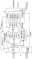
図4は、その動作を機能的にブロック化して示すブロック図である。尚、同図は、具体的には上記したレーン200,202(第1、第2の制御系)において4個のCPUの中、CPU200a,202aが平行して行う動作である。
FIG. 4 is a block diagram showing the operation in functional blocks. Specifically, FIG. 6 shows operations performed in parallel by the
以下説明すると、エンジン10の運転状態を示す前記したセンサ出力(出力された値)は、先ず図示しないローパスフィルタに入力されてノイズ成分が除去され、波形処理がなされた後、カウンタなどにおいて運転状態を示すパラメータ(例えばN1センサ62でいえばrpm相当の値)に変換された後、10msecごとに初期チェックブロック300に入力され、そこで適宜設定された許容範囲にあるか否かチェックされる。尚、ローパスフィルタはセンサ出力に応じてセンサ出力のノイズ成分が可能な限り除去されるようにカットオフ周波数が設定され、それによってセンサ出力に重畳するノイズ成分が除去される。
In the following, the sensor output (output value) indicating the operation state of the
尚、センサ出力は、前記した低圧タービン回転数を示すN1センサ62、高圧タービン回転数を示すN2センサ64など前記したセンサの全ての出力を含む。センサは少なくとも2個設けられるが、4個設けられるN2センサ64の出力については、レーン200,202で2個ずつを対象として以下に述べる判定が行われる。
The sensor output includes all outputs of the above-described sensors such as the
初期チェックブロック300の出力は故障判定ブロック302に送られ、そこで許容範囲内にないと判定された回数がカウントされて所定の値と比較されることで、センサが故障しているか否か判定される。故障判定ブロック302の出力は出力分離ブロック304に送られると共に、初期チェックブロック300の出力も出力分離ブロック304に送られる。出力分離ブロック304は、故障判定ブロック302の判定結果に基づき、入力したセンサ出力の中、故障と判定されなかったセンサ出力を同種の値ごとに分離して出力する。尚、初期チェックブロック300は判定留保としたセンサ出力については一時休止フラグFlagを付して出力する。
The output of the
図4で、「4値OK」と示すものは、N2センサ64の出力4個が全て正常と判定されて出力された場合を、「3値OK」と示すものはその4個の中の3個が正常と判断された場合を、「2値OK」と示すものはその4個の中の2個が正常と判断された場合を、「1値OK」と示すものはその4個の中の1個が正常と判定された場合を示す。また、「全NG」と示すものは、N2センサ64の出力が故障と判定された場合を示す。これはTLAセンサ84など他のセンサについても同様であり、「3値OK」と示すものは,TLAセンサなどの3個の出力を有するものの全てがそのまま正常と判定された場合を、「2値OK」と示すものは3個の出力の中の2個が正常と判断された場合、およびN1センサ62などの2個の出力がそのまま正常と判断された場合を、「1値OK」と示すものはN1センサ62などの2個の出力の中の1個が正常と判定された場合を示す。「全NG」と示すものが、そのセンサが故障と判定された場合を示すことも同様である。
In FIG. 4, “4 value OK” indicates that all four outputs of the
出力分離ブロック304の出力は出力選別ブロック306に送られる。前記した初期チェックブロック300で判定保留とされて一時休止フラグFlagを付して出力されたセンサ出力も出力選別ブロック306に送られる。出力選別ブロック306では判定保留とされたセンサ出力が除去されつつ、比較すべき信号の選別が行われた後、可否判断ブロック308に送られ、そこで同種の出力同士が同一と許容できる範囲内にあるか否か比較して判断され、燃料供給制御に使用可能なセンサ出力か否か可否判定される。
The output of the
可否判断ブロック308に記載されている比較に関して下から説明すると、1値のみ入力されたときは比較相手が存在しないことから、そのまま制御信号として出力される。この場合、1個の制御信号のみ出力されることから、レーン200,202のいずれかは他レーンに入力されるその信号を参照することになる。
The comparison described in the possibility determination block 308 will be described below. When only one value is input, since there is no comparison partner, the comparison signal is output as it is. In this case, since only one control signal is output, one of the
2値比較の場合、相互に同一と許容できる範囲内にあるか判断され、許容できる範囲内にあると判断された場合、2個の信号が制御信号としてレーン200,202のそれぞれに出力される。
In the case of binary comparison, it is determined whether they are within an allowable range that is the same as each other. If it is determined that they are within an allowable range, two signals are output as control signals to the
記載は省略するが、他のパラメータについても同様な範囲が設定される。尚、この範囲はエンジン10の運転状態が過渡と定常のいずれにあるかによって異なる値に設定されることから、後述する運転状態の判定結果に基づいていずれかを選択する。また、この範囲は続いて述べる3値比較および4値比較においても使用される。
Although not described, similar ranges are set for other parameters. Note that this range is set to a different value depending on whether the operating state of the
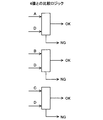
3値比較に関しては、図5に示す如く、2値比較を3回行い、図6に示すように比較結果を求め、それに基づいて制御信号として使用可能な信号を選定すると共に、併せて異常信号であるか否かの可否判断を行う。例えば、図3を参照して説明すると、Aは自レーンに入力されるセンサ出力,Bは他レーンに入力されるセンサ出力,CはCANを介して入力されるセンサ出力を示し、これは優先度の順も示す。即ち、全て同一と判断された場合、図示の如く、Aが制御信号として使用されることを意味する。 As for the ternary comparison, as shown in FIG. 5, the binary comparison is performed three times, the comparison result is obtained as shown in FIG. 6, and a signal usable as a control signal is selected based on the comparison result. It is determined whether or not. For example, referring to FIG. 3, A is a sensor output input to its own lane, B is a sensor output input to another lane, and C is a sensor output input via CAN. The order of degrees is also shown. That is, if all are determined to be the same, it means that A is used as a control signal as shown.
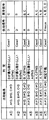
図6に示す如く、比較結果に基づいて図示のような論理で判定がなされる。Case1は、異常信号がないと判定された場合、Case2は異常信号が1個と判定された場合、Case3は、全て異常信号と判定された場合である。Case3の場合、そのセンサの出力の全てについて異常検知とし、制御信号として使用中のときは、その値に固定して使用し続けると共に(Freeze)、Warning(警告)を出力する。Case1の中、A丸付き数字2の場合、極めて低いが、生じ得る可能性もあることから、Aが最も確からしいと判定する。
As shown in FIG. 6, the determination is made based on the comparison result and the logic as shown.
4値比較に関しては、図7に示す如く、4値の中の3値を用いて2値比較を3回行い、正常と判定された信号(センサ出力)と、4値目を比較する。4値はN2センサ64の出力に限定されることから、Aは自レーンに入力されるN2センサAの出力,Bは他レーンに入力されるN2センサAの出力,Cは自レーンに入力されるN2センサBの出力、Dは他レーンに入力されるN2センサBの出力を意味し、優先度もその順となる。従って、優先度の高い順のA,B,Cについて3値比較を行い、それらが全て正常と判定された場合(Case1)、あるいは3値の中の1値が異常信号と判定された場合(Case2)、それらと優先度において最も低いDとの2値比較を行う。尚、3値比較自体は、Warning(警告)を出力しない点を除くと、図5に示したものと異ならない。
As for the 4-value comparison, as shown in FIG. 7, the binary comparison is performed 3 times using the 3 values of the 4 values, and the signal determined as normal (sensor output) is compared with the 4th value. Since the four values are limited to the output of the
図7に示す如く、3値比較結果がCase1の場合、Dとの2値比較結果は、4個の出力が正常(全信号正常)か、あるいはDが異常(Single Fail)となる。3値比較結果がCase2の場合、Dとの2値比較結果は、4個の中の1個が異常(Single Fail)か、あるいはDとその他の出力1個が異常(Double Fail)となる。
As shown in FIG. 7, when the ternary comparison result is
また、3値比較結果がCase3の場合も、Dとの3値比較を行い、可能ならば、使用信号を選択する。図8にその比較ロジックを、図9に比較結果に基づく可否判断を示す。図9にCase1, Case2と示す場合、Dとの再比較によって使用信号が選択された場合を示す。尚、図示の如く、Dとの再比較によって一旦異常と判定されたA,B,C信号のいずれかが使用信号として選択されることもある。尚、図9にCase 3と示す場合は、図6のCase3の場合と同様、そのセンサの出力の全てについて異常検知とし、制御信号として使用中のときは、その値に固定して使用し続けると共に(Freeze)、Warning(警告)を出力する。
Also, when the ternary comparison result is Case 3, a ternary comparison with D is performed, and if possible, a use signal is selected. FIG. 8 shows the comparison logic, and FIG. 9 shows the determination of availability based on the comparison result. When
図4の説明に戻ると、初期チェックブロック300の出力は過渡・定常判定ブロック310にも入力され、そこでエンジン10の運転状態が判定される。
Returning to the description of FIG. 4, the output of the
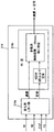
図10は、過渡・定常判定ブロック310の構成を詳細に示すブロック図である。
FIG. 10 is a block diagram showing in detail the configuration of the transient / steady
過渡・定常判定に使用されるセンサ出力(パラメータ)は、図示の如く、N1センサ62、A,B2個のN2センサ64、およびEGTセンサ76の出力ならびにP3センサ74の出力が1個ずつ使用される(具体的には、正常と判定される限り、優先度の高い出力Aが使用される)。
As shown in the figure, the sensor outputs (parameters) used for transient / steady state judgment are the outputs of the
具体的には、レーン200の判定にはN1,N2A,B,EGTの4種が、レーン202の判定にはそれらにP3を加えた5種のパラメータが使用される。レーン202の判定パラメータにP3が追加されるのは、レーン202はセカンダリであり、レーン200に異常が生じた場合、レーン200に代わって燃料供給制御を実行するレーンであることから、判断をより慎重に行うためである。
Specifically, four types of N1, N2A, B, and EGT are used for the determination of the
それら4種あるいは5種の出力は、10msecごとに変化率しきい値ブロック310aに入力され、センサごとに予め設定された変化率しきい値と比較される。
These four or five types of outputs are input to the change
図10に示す如く、ブロック310aでは入力された値を対応するしきい値と比較し、比較結果を判定ブロック310bに送る。判定ブロック310bでは、比較結果に基づき、40msecごとに運転状態が判定される。判定は原則的には多数決でなされるが、具体的には以下のようになされる。即ち、レーン200における判定では、4値中2値以上(半数以上)が対応するしきい値以上であるとき、エンジン10が過渡状態にあると判定する一方、4値中2値以上が対応するしきい値未満である状態が連続3回生じたか、または4回中3回生じると共に、4値中2値以上(半数以上)が対応するしきい値以上であるとき、エンジン10が定常状態にあると判定する。比較は、10msecごとに、入力値としきい値との間でなされることから、40msecの間の比較回数は4回となる。尚、4値中2値同士の同数となったときは、N2センサ64の出力を1個除去し、残りの3値で判定して判定結果が過半数となるか否か判断する。
As shown in FIG. 10, in
レーン202における判定では、5値中3値以上が対応するしきい値以上であるとき、エンジン10が過渡状態にあると判定する一方、5値中3値以上が対応するしきい値未満である状態が連続3回生じたか、または4回中3回生じたとき、エンジン10が定常状態にあると判定する。
In the determination in
また、レーン200,202におけるTLAを用いた判定では、3値中2値以上が対応するしきい値以上であるとき、エンジン10が過渡状態にあると判定する一方、3値中2値以上が対応するしきい値未満である状態が連続3回生じたか、または4回中3回生じると共に、5値中3値以上が対応するしきい値以上であるとき、エンジン10が定常状態にあると判定する。
Further, in the determination using the TLA in the
尚、上記では所定時間ごとに出力される値の変化率をしきい値として判定するようにしたが、所定時間ごとに出力された値同士の差を求めてしきい値として判定するようにしても良い。 In the above, the change rate of the value output every predetermined time is determined as the threshold value. However, the difference between the values output every predetermined time is obtained and determined as the threshold value. Also good.
過渡・定常判定ブロック310は、判定結果を出力する。 The transient / steady state determination block 310 outputs a determination result.
図4の説明に戻ると、過渡・定常判定ブロック310の判定結果は可否判断ブロック308に送られ、ブロック308では送られた判定結果に応じ、同一と許容できる範囲について過渡と定常のいずれかを選択して使用する。また、過渡・定常判定ブロック310の判定結果に基づいて相応する燃料供給制御が実行される。
Returning to the description of FIG. 4, the determination result of the transient / steady
尚、N1,P3,EGTなどに関しては合成信号作成部312で他のパラメータより推測された値を用いて合成信号が作成され、可否判断ブロック308においてそれとの比較を通じて可否判断が再度なされる。
For N1, P3, EGT, etc., a synthesized signal is created by using the value estimated from other parameters by the synthesized
上記の如く、この実施例にあっては、少なくとも低圧タービン(42)と高圧タービン(40)からなる2基のタービンを備えたガスタービン・エンジン(10)において、前記低圧タービンの回転数を示す出力を生じる、少なくとも1個の低圧タービン回転数センサ(N1センサ62)、前記高圧タービンの回転数を示す出力を生じる、少なくとも1個の高圧タービン回転数センサ(N2センサ64)、前記低圧タービンから排出される排ガスの温度を示す出力を生じる、少なくとも1個の温度センサ(EGTセンサ76)、少なくとも前記センサ群から出力された値を入力し、入力された値の全部または一部に基づいて前記エンジンへの燃料供給を制御する第1の制御系(プライマリレーン200)を備えたガスタービン・エンジンの制御装置において、前記第1の制御系が、前記センサ群から出力された値を入力し、所定時間ごとに前記出力された値の変化率あるいは差をそれぞれ対応する所定のしきい値と比較する比較手段(変化率しきい値ブロック310a)、および前記所定のしきい値以上と判断されたセンサ出力の個数が所定数以上であるとき、より具体的には4値中2値あるいは5値中3値以上であるとき、前記エンジンが過渡状態にあると判定する一方、前記出力された値が前記所定のしきい値未満と判断された回数が比較回数の中の半数以上であり、かつ前記センサ出力の個数が所定数以上であるとき、より具体的には連続3回または4回中3回以上であるとき、前記エンジンが定常状態にあると判定する運転状態判定手段(判定ブロック310b)からなる過渡・定常判定手段(過渡・定常判定ブロック310)を備える如く構成した。これにより、ノイズなどの影響を受けることなく、エンジン10が定常状態にあるか、あるいは加速も含めた過渡状態にあるかを精度良く判定することができる。
As described above, in this embodiment, in the gas turbine engine (10) including at least two turbines including the low pressure turbine (42) and the high pressure turbine (40), the rotational speed of the low pressure turbine is shown. At least one low pressure turbine speed sensor (N1 sensor 62) that produces an output, at least one high pressure turbine speed sensor (N2 sensor 64) that produces an output indicative of the speed of the high pressure turbine, from the low pressure turbine At least one temperature sensor (EGT sensor 76) that generates an output indicating the temperature of the exhaust gas to be discharged, inputs a value output from at least the sensor group, and based on all or part of the input value Control of a gas turbine engine having a first control system (primary lane 200) for controlling fuel supply to the engine In the apparatus, the first control system inputs a value output from the sensor group, and compares a change rate or a difference of the output value with a corresponding predetermined threshold value every predetermined time. When the number of means (change
さらに、前記第1の制御系に異常が生じたとき、前記第1の制御系に代わって前記エンジンへの燃料供給を制御する第2の制御系(セカンダリレーン200)を備えると共に、前記第2の制御系が前記過渡・定常判定手段(過渡・定常判定ブロック310)を備える如く構成した。これにより、前記した効果に加え、2つの制御系の判定結果が異なる場合、センサ出力に異常が生じたと推定することができ、それに応じて適切な対応をとることができる。 Furthermore, when an abnormality occurs in the first control system, a second control system (secondary lane 200) is provided for controlling the fuel supply to the engine in place of the first control system. The control system is configured to include the transient / steady state determination means (transient / steady state determination block 310). Thereby, in addition to the above-described effects, when the determination results of the two control systems are different, it can be estimated that an abnormality has occurred in the sensor output, and an appropriate response can be taken accordingly.
また、前記第1の制御系と第2の制御系の過渡・定常判定手段(過渡・定常判定ブロック310)のいずれかが、より具体的には第2の制御系が第4のセンサ(より具体的にはP3センサ74)を備える如く構成した。従って、第4のセンサとして例えば高圧タービンで駆動される圧縮機の出力圧を検出するP3センサ74を使用するとき、運転状態の変化は高圧タービン側に時間的に先行して生じることから、そのパラメータを加えて判定することで運転状態の変化を精度良く判定できると共に、2つの制御系の判定結果が異なる場合、サージが生じた可能性があると予測できて適切な対応をとることができる。
Further, any one of the transient / steady state determination means (transient / steady state determination block 310) of the first control system and the second control system, more specifically, the second control system is connected to the fourth sensor (more Specifically, it is configured to include a P3 sensor 74). Therefore, when the
また、前記第1の制御系と第2の制御系がそれぞれ、前記センサ群の中、同種のセンサからの出力同士が同一と許容できる範囲内にあるか否か判断して前記燃料供給制御に使用可能なセンサ出力か否か判定するセンサ出力可否判定手段(可否判断ブロック308)、および前記判定された運転状態に応じて前記許容できる範囲を変更する許容範囲変更手段(可否判断ブロック308)、を備える如く構成した。これにより、前記した効果に加え、燃料供給制御に使用可能なセンサ出力か否かを適切に判定でき、よって燃料供給制御を一層適切に行うことができる。 Further, each of the first control system and the second control system determines whether or not outputs from the same type of sensors in the sensor group are within the allowable range of the same, and performs the fuel supply control. Sensor output availability determination means for determining whether or not the sensor output can be used (allowability determination block 308), and allowable range change means for changing the allowable range according to the determined operating state (allowability determination block 308); It comprised so that it might be equipped with. Thereby, in addition to the above-described effects, it is possible to appropriately determine whether or not the sensor output can be used for the fuel supply control, and thus the fuel supply control can be more appropriately performed.
また、この実施例にあっては、少なくとも1基のタービン(高圧タービン40)を備えたガスタービン・エンジンにおいて、前記タービンの回転数を示す出力を生じる、少なくとも2個のタービン回転数センサ(N2センサ64)、少なくとも前記センサから出力された値を入力し、少なくとも入力された値に基づいて前記エンジンへの燃料供給を制御する第1の制御系(プライマリレーン200)、および少なくとも前記センサと同一のセンサを備えると共に、前記同一のセンサから出力された値を入力し、前記第1の制御系に異常が生じたとき、前記第1の制御系に代わって少なくとも入力された値に基づいて前記エンジンへの燃料供給を制御する第2の制御系(セカンダリレーン202)を備えたガスタービン・エンジンの制御装置において、前記第1、第2の制御系が、前記少なくとも2個のタービン回転数センサから出力される少なくとも4個の値を入力し、その中の少なくとも3個の値が同一と許容できる範囲内にあるか否か判断する3値比較手段(可否判断ブロック308)、および前記少なくとも3値がそれぞれ残りの少なくとも1個の値と同一と許容できる範囲内にあるか否か判断して前記燃料供給制御に使用可能なセンサ出力か否か判定する4値比較手段(可否判断ブロック308)を備える如く構成した。 In this embodiment, in a gas turbine engine equipped with at least one turbine (high pressure turbine 40), at least two turbine rotation speed sensors (N2) that generate an output indicating the rotation speed of the turbine. Sensor 64), at least a value output from the sensor, a first control system (primary lane 200) for controlling fuel supply to the engine based on at least the input value, and at least the same as the sensor And the value output from the same sensor is input, and when an abnormality occurs in the first control system, based on at least the input value instead of the first control system A control apparatus for a gas turbine engine having a second control system (secondary lane 202) for controlling fuel supply to an engine The first and second control systems input at least four values output from the at least two turbine rotation speed sensors, and at least three of the values are within the allowable range. The fuel supply by determining whether or not the at least three values are within the allowable range that is the same as at least one remaining value. A 4-value comparing means (availability determination block 308) for determining whether or not the sensor output can be used for control is provided.
より具体的には、少なくとも低圧タービン(42)と高圧タービン(40)からなる2基のタービンを備えたガスタービン・エンジン(10)において、前記低圧タービンの回転数を示す出力を生じる、少なくとも1個の低圧タービン回転数センサ(N1センサ62)、前記高圧タービンの回転数を示す出力を生じる、少なくとも2個の高圧タービン回転数センサ(N2センサ64)、前記高圧タービンに供給される燃焼ガスの温度を示す出力を生じる、少なくとも1個の温度センサ(EGTセンサ76)、少なくとも前記センサ群から出力された値を入力し、入力された値の全部または一部に基づいて前記エンジンへの燃料供給を制御する第1の制御系(プライマリレーン200)、および少なくとも前記センサ群と同一のセンサ群を備えると共に、前記同一のセンサ群から出力された値を入力し、前記第1の制御系に異常が生じたとき、前記第1の制御系に変わって入力された値の全部または一部に基づいて前記エンジンへの燃料供給を制御する第2の制御系(セカンダリレーン202)、を備えたガスタービン・エンジンの制御装置において、前記第1、第2の制御系が、前記少なくとも2個の高圧タービン回転数センサ(N2センサ64)から出力される少なくとも4個の値を入力し、その中の少なくとも3個の値が同一と許容できる範囲内にあるか否か判断する3値比較手段(可否判断ブロック308)、および前記少なくとも3値がそれぞれ残りの少なくとも1個の値と同一と許容できる範囲内にあるか否か判断して前記燃料供給制御に使用可能なセンサ出力か否か判定する4値比較手段(可否判断ブロック308)を備える如く構成した。 More specifically, in a gas turbine engine (10) having two turbines consisting of at least a low-pressure turbine (42) and a high-pressure turbine (40), at least 1 which produces an output indicating the rotational speed of the low-pressure turbine. Low pressure turbine speed sensors (N1 sensor 62), at least two high pressure turbine speed sensors (N2 sensor 64) producing an output indicative of the speed of the high pressure turbine, the combustion gas supplied to the high pressure turbine At least one temperature sensor (EGT sensor 76) that generates an output indicating temperature, inputs at least a value output from the sensor group, and supplies fuel to the engine based on all or part of the input value A first control system (primary lane 200) for controlling the vehicle, and at least the same sensor group as the sensor group A value output from the same sensor group is input, and when an abnormality occurs in the first control system, based on all or a part of the input value instead of the first control system. In a gas turbine engine control device comprising a second control system (secondary lane 202) for controlling fuel supply to the engine, the first and second control systems are the at least two high-pressure turbines. At least four values output from the rotation speed sensor (N2 sensor 64) are inputted, and a three-value comparison means (determining whether or not it is possible) determines whether or not at least three of the values are within the allowable range. Block 308), and whether each of the at least three values is within an allowable range equal to at least one of the remaining values to determine whether the sensor output can be used for the fuel supply control. It was composed as comprising a four-value comparison means (whether decision block 308) to.
これにより、3値比較と4値比較を行うことで、高圧タービン回転数センサ(N2センサ64)などが複数個設けられるときも、その中から燃料供給制御などに使用可能なセンサ出力(制御信号)を的確に選択することができ、制御精度を向上させることができる。 Accordingly, even when a plurality of high-pressure turbine rotation speed sensors (N2 sensors 64) are provided by performing three-value comparison and four-value comparison, sensor outputs (control signals) that can be used for fuel supply control, etc. ) Can be selected accurately, and the control accuracy can be improved.
また、前記3値比較手段および4値比較手段(可否判断ブロック308)は、前記燃料制御に使用不可能なセンサ出力(異常信号)も判定する如く構成した。これにより、前記した効果に加え、そのような異常な信号が制御に使用されるのを回避することができ、よって制御精度を一層向上させることができる。 Further, the three-value comparison means and the four-value comparison means (availability determination block 308) are configured to determine a sensor output (abnormal signal) that cannot be used for the fuel control. As a result, in addition to the effects described above, it is possible to avoid such an abnormal signal being used for control, thereby further improving the control accuracy.
さらに、前記タービンから排出される燃焼ガスの温度を示す出力を生じる、少なくとも1個の温度センサ(EGTセンサ76)、少なくとも前記タービン回転数センサおよび温度センサから出力された値を入力し、所定時間ごとに前記出力された値の変化率あるいは差をそれぞれ対応する所定のしきい値と比較し、比較結果に基づいて前記エンジンが定常状態と過渡状態のいずれにあるか判定する運転状態判定手段(過渡・定常判定ブロック310)、および前記判定された運転状態に応じて前記許容できる範囲を変更する許容範囲変更手段(可否判断ブロック308)、を備える如く構成した。 Further, at least one temperature sensor (EGT sensor 76) that generates an output indicating the temperature of the combustion gas discharged from the turbine, at least the values output from the turbine rotation speed sensor and the temperature sensor are input, and a predetermined time An operating state determining means that compares the change rate or difference of the output value with a corresponding predetermined threshold value for each time and determines whether the engine is in a steady state or a transient state based on the comparison result ( A transient / steady state determination block 310), and an allowable range changing means (allowability determination block 308) for changing the allowable range in accordance with the determined operating state.
より具体的には、さらに、前記低圧タービン回転数センサ(N1センサ62)、高圧タービン回転数センサ(N2センサ64)および温度センサ(EGTセンサ76)から出力された値を入力し、所定時間ごとに前記出力された値の変化率あるいは差をそれぞれ対応する所定のしきい値と比較し、比較結果に基づいて前記エンジンが過渡状態と定常状態のいずれにあるか判定する運転状態判定手段(過渡・定常判定ブロック310)、および前記判定された運転状態に応じて前記許容できる範囲を変更する許容範囲変更手段(可否判断ブロック308)を備える如く構成した。 More specifically, the values output from the low-pressure turbine rotational speed sensor (N1 sensor 62), the high-pressure turbine rotational speed sensor (N2 sensor 64), and the temperature sensor (EGT sensor 76) are further input at predetermined time intervals. The change rate or difference of the output value is compared with a corresponding predetermined threshold value, and based on the comparison result, it is determined whether the engine is in a transient state or a steady state. A stationary determination block 310) and an allowable range changing means (allowability determination block 308) for changing the allowable range according to the determined operating state are provided.
これにより、燃料供給制御などに使用可能なセンサ出力を一層的確に選択することができ、制御精度を一層向上させることができる。 Thereby, the sensor output that can be used for fuel supply control and the like can be selected more accurately, and the control accuracy can be further improved.
尚、上記した実施例において、航空機用ガスタービン・エンジンとしてはターボファン・エンジンを例にとったが、ターボジェット・エンジン、ターボプロップ・エンジンおよびターボシャフト・エンジンなどであっても良い。 In the above-described embodiment, a turbofan engine is taken as an example of an aircraft gas turbine engine, but a turbojet engine, a turboprop engine, a turboshaft engine, or the like may be used.
10 航空機用ガスタービン・エンジン(ターボファン・エンジン)
12 ファン
12a ロータ
14 ステータ
16 低圧圧縮機
24 高圧圧縮機
24a ロータ
24b ステータ
26 燃焼器
28 燃料ノズル
30 FCU(Fuel Control Unit。燃料制御部)
32 燃料調量バルブ
40 高圧タービン
40a 高圧タービン軸
42 低圧タービン
42a 低圧タービン軸
62 N1センサ
64 N2センサ
68 T1センサ
70 P1センサ
72 P0センサ
74 P3センサ
76 EGTセンサ
80 ECU(Electronic Control Unit 。燃料制御部)
82 スラストレバー(スロットルレバー)
98 トルクモータ
200 プライマリレーン(第1の制御系)
202 セカンダリレーン(第2の制御系)
302 故障判定ブロック
308 可否判断ブロック
310 過渡・定常判定ブロック
10. Aircraft gas turbine engine (turbofan engine)
12
32
82 Thrust lever (throttle lever)
98
202 Secondary lane (second control system)
302 Failure determination block 308 Acceptability determination block 310 Transient / steady state determination block
Claims (3)
a.前記タービンの回転数を示す出力を生じる、少なくとも2個のタービン回転数センサ、
b.少なくとも前記センサから出力された値を入力し、少なくとも入力された値に基づいて前記エンジンへの燃料供給を制御する第1の制御系、
および
c.少なくとも前記センサと同一のセンサを備えると共に、前記同一のセンサから出力された値を入力し、前記第1の制御系に異常が生じたとき、前記第1の制御系に代わって少なくとも入力された値に基づいて前記エンジンへの燃料供給を制御する第2の制御系、
を備えたガスタービン・エンジンの制御装置において、前記第1、第2の制御系が、
d.前記少なくとも2個のタービン回転数センサから出力される少なくとも4個の値を入力し、その中の少なくとも3個の値が同一と許容できる範囲内にあるか否か判断する3値比較手段、
および
e.前記少なくとも3値がそれぞれ残りの少なくとも1個の値と同一と許容できる範囲内にあるか否か判断して前記燃料供給制御に使用可能なセンサ出力か否か判定する4値比較手段、
を備えることを特徴とするガスタービン・エンジンの制御装置。 In a gas turbine engine with at least one turbine,
a. At least two turbine speed sensors producing an output indicative of the turbine speed;
b. A first control system that inputs at least a value output from the sensor and controls fuel supply to the engine based on at least the input value;
And c. At least the same sensor as the sensor is provided, and a value output from the same sensor is input. When an abnormality occurs in the first control system, at least the first control system is input. A second control system for controlling fuel supply to the engine based on a value;
A control apparatus for a gas turbine engine comprising: the first and second control systems,
d. Three-value comparison means for inputting at least four values output from the at least two turbine rotation speed sensors and determining whether or not at least three of the values are within the allowable range.
And e. 4-value comparing means for determining whether or not the at least three values are within the allowable range equal to at least one of the remaining values, and determining whether or not the sensor output can be used for the fuel supply control;
A control device for a gas turbine engine, comprising:
f.前記タービンから排出される燃焼ガスの温度を示す出力を生じる、少なくとも1個の温度センサ、
g.少なくとも前記タービン回転数センサおよび温度センサから出力された値を入力し、所定時間ごとに前記出力された値の変化率あるいは差をそれぞれ対応する所定のしきい値と比較し、比較結果に基づいて前記エンジンが定常状態と過渡状態のいずれにあるか判定する運転状態判定手段、
および
h.前記判定された運転状態に応じて前記許容できる範囲を変更する許容範囲変更手段、を備えたことを特徴とする請求項1または2記載のガスタービン・エンジンの制御装置。
further,
f. At least one temperature sensor producing an output indicative of the temperature of the combustion gas exhausted from the turbine;
g. At least the values output from the turbine speed sensor and the temperature sensor are input, and the rate of change or difference of the output value is compared with a corresponding predetermined threshold value every predetermined time, and based on the comparison result Operating state determination means for determining whether the engine is in a steady state or a transient state;
And h. The control device for a gas turbine engine according to claim 1, further comprising an allowable range changing unit that changes the allowable range in accordance with the determined operating state.
Priority Applications (4)
| Application Number | Priority Date | Filing Date | Title |
|---|---|---|---|
| JP2004106422A JP4434815B2 (en) | 2004-03-31 | 2004-03-31 | Control device for gas turbine engine |
| US11/090,125 US7246495B2 (en) | 2004-03-31 | 2005-03-28 | Control system for gas-turbine engine |
| CA002503102A CA2503102C (en) | 2004-03-31 | 2005-03-30 | Control system for gas-turbine engine |
| GB0506587A GB2412753B (en) | 2004-03-31 | 2005-03-31 | Control system for gas-turbine engine |
Applications Claiming Priority (1)
| Application Number | Priority Date | Filing Date | Title |
|---|---|---|---|
| JP2004106422A JP4434815B2 (en) | 2004-03-31 | 2004-03-31 | Control device for gas turbine engine |
Publications (2)
| Publication Number | Publication Date |
|---|---|
| JP2005291070A true JP2005291070A (en) | 2005-10-20 |
| JP4434815B2 JP4434815B2 (en) | 2010-03-17 |
Family
ID=34567598
Family Applications (1)
| Application Number | Title | Priority Date | Filing Date |
|---|---|---|---|
| JP2004106422A Expired - Fee Related JP4434815B2 (en) | 2004-03-31 | 2004-03-31 | Control device for gas turbine engine |
Country Status (4)
| Country | Link |
|---|---|
| US (1) | US7246495B2 (en) |
| JP (1) | JP4434815B2 (en) |
| CA (1) | CA2503102C (en) |
| GB (1) | GB2412753B (en) |
Cited By (6)
| Publication number | Priority date | Publication date | Assignee | Title |
|---|---|---|---|---|
| JP2007192138A (en) * | 2006-01-19 | 2007-08-02 | Mitsubishi Heavy Ind Ltd | Method and device for monitoring anomaly in gas turbine |
| JP2008157458A (en) * | 2006-12-22 | 2008-07-10 | General Electric Co <Ge> | Variable magnetic coupling of rotating machinery |
| JP2011043135A (en) * | 2009-08-24 | 2011-03-03 | Honda Motor Co Ltd | Control device for aircraft gas turbine engine |
| JP2011525592A (en) * | 2008-06-23 | 2011-09-22 | スネクマ | Method and system for determining the angular position of a turbojet rotor |
| JP2012062833A (en) * | 2010-09-16 | 2012-03-29 | Honda Motor Co Ltd | Temperature estimation apparatus for aeroplane gas turbine engine |
| JP2015102071A (en) * | 2013-11-27 | 2015-06-04 | 三菱日立パワーシステムズ株式会社 | Fuel regulator, combustor, gas turbine, gas turbine system, fuel regulator control method, and program |
Families Citing this family (21)
| Publication number | Priority date | Publication date | Assignee | Title |
|---|---|---|---|---|
| JP4434834B2 (en) * | 2004-05-26 | 2010-03-17 | 本田技研工業株式会社 | Control device for gas turbine engine |
| JP4657800B2 (en) * | 2005-05-16 | 2011-03-23 | 本田技研工業株式会社 | Control device for aircraft gas turbine engine |
| GB0601775D0 (en) * | 2006-01-28 | 2006-03-08 | Rolls Royce Plc | An Actuator Arrangement And A Method Of Operating An Actuator |
| US20090240373A1 (en) * | 2008-03-23 | 2009-09-24 | Brown Rork S | Establishing a use cycle using a container condition |
| US20100005657A1 (en) * | 2008-07-10 | 2010-01-14 | Van Vactor David R | Methods and systems to facilitate over-speed protection |
| US8321119B2 (en) * | 2008-07-10 | 2012-11-27 | General Electric Company | Methods and systems to facilitate over-speed protection |
| US8224552B2 (en) * | 2008-07-10 | 2012-07-17 | General Electric Company | Methods and systems to facilitate over-speed protection |
| FR2939509B1 (en) * | 2008-12-09 | 2011-03-04 | Snecma | METHOD AND SYSTEM FOR ESTIMATING A VEIN TEMPERATURE IN A TURBOKIN. |
| FR2939508B1 (en) * | 2008-12-09 | 2011-01-07 | Snecma | METHOD AND SYSTEM FOR CORRECTING MEASUREMENT SIGNAL OF TEMPERATURE. |
| DE102008054589B3 (en) * | 2008-12-12 | 2010-08-19 | Thielert Aircraft Engines Gmbh | Engine control system for a jet diesel engine |
| FR2939924B1 (en) * | 2008-12-15 | 2012-10-12 | Snecma | IDENTIFICATION OF FAILURES IN AN AIRCRAFT ENGINE |
| US8682562B2 (en) * | 2009-05-08 | 2014-03-25 | Rolls-Royce Corporation | Turbine engine thrust scheduling |
| US20110018273A1 (en) * | 2009-07-27 | 2011-01-27 | Rolls-Royce Corporation | Starter/generator integrated into compressor of turbine engine |
| US8745990B2 (en) * | 2009-07-27 | 2014-06-10 | Rolls-Royce Corporation | Gas turbine engine with integrated electric starter/generator |
| FR2982320B1 (en) * | 2011-11-08 | 2014-01-10 | Thales Sa | DIGITAL REGULATION SYSTEM WITH FULL AUTHORITY FOR AN AIRCRAFT ENGINE |
| US9869249B2 (en) | 2012-01-31 | 2018-01-16 | United Technologies Corporation | Speed sensor probe location in gas turbine engine |
| US8459038B1 (en) | 2012-02-09 | 2013-06-11 | Williams International Co., L.L.C. | Two-spool turboshaft engine control system and method |
| US9322341B2 (en) * | 2013-03-12 | 2016-04-26 | Pratt & Whitney Canada Corp. | System and method for engine transient power response |
| US9982607B2 (en) | 2015-07-20 | 2018-05-29 | Rolls-Royce North American Technologies, Inc. | Shaft failure detection using passive control methods |
| US11092136B2 (en) * | 2018-05-04 | 2021-08-17 | Raytheon Technologies Corporation | Systems and methods for optimal speed protection for power turbine governing |
| US11629649B2 (en) | 2020-05-11 | 2023-04-18 | Raytheon Technologies Corporation | Gas turbine engine with speed sensor |
Family Cites Families (6)
| Publication number | Priority date | Publication date | Assignee | Title |
|---|---|---|---|---|
| US3729929A (en) | 1971-03-09 | 1973-05-01 | Westinghouse Electric Corp | Fuel control system for a gas turbine |
| US4641517A (en) * | 1984-12-20 | 1987-02-10 | United Technologies Corporation | Control system actuator position synthesis for failure detection |
| US4712372A (en) * | 1985-09-18 | 1987-12-15 | Avco Corporation | Overspeed system redundancy monitor |
| DE4005546A1 (en) | 1990-02-22 | 1991-08-29 | Gutehoffnungshuette Man | METHOD FOR REDUNDANT SPEED CONTROL AND DEVICE FOR CARRYING OUT THIS METHOD |
| JP3348444B2 (en) | 1992-07-31 | 2002-11-20 | 石川島播磨重工業株式会社 | Parameter abnormal runout detection method |
| US6176074B1 (en) * | 1998-06-05 | 2001-01-23 | Pratt & Whitney Canada Corp. | Shaft decouple logic for gas turbine |
-
2004
- 2004-03-31 JP JP2004106422A patent/JP4434815B2/en not_active Expired - Fee Related
-
2005
- 2005-03-28 US US11/090,125 patent/US7246495B2/en active Active
- 2005-03-30 CA CA002503102A patent/CA2503102C/en not_active Expired - Fee Related
- 2005-03-31 GB GB0506587A patent/GB2412753B/en not_active Expired - Fee Related
Cited By (6)
| Publication number | Priority date | Publication date | Assignee | Title |
|---|---|---|---|---|
| JP2007192138A (en) * | 2006-01-19 | 2007-08-02 | Mitsubishi Heavy Ind Ltd | Method and device for monitoring anomaly in gas turbine |
| JP2008157458A (en) * | 2006-12-22 | 2008-07-10 | General Electric Co <Ge> | Variable magnetic coupling of rotating machinery |
| JP2011525592A (en) * | 2008-06-23 | 2011-09-22 | スネクマ | Method and system for determining the angular position of a turbojet rotor |
| JP2011043135A (en) * | 2009-08-24 | 2011-03-03 | Honda Motor Co Ltd | Control device for aircraft gas turbine engine |
| JP2012062833A (en) * | 2010-09-16 | 2012-03-29 | Honda Motor Co Ltd | Temperature estimation apparatus for aeroplane gas turbine engine |
| JP2015102071A (en) * | 2013-11-27 | 2015-06-04 | 三菱日立パワーシステムズ株式会社 | Fuel regulator, combustor, gas turbine, gas turbine system, fuel regulator control method, and program |
Also Published As
| Publication number | Publication date |
|---|---|
| US20050217274A1 (en) | 2005-10-06 |
| GB0506587D0 (en) | 2005-05-04 |
| GB2412753A (en) | 2005-10-05 |
| CA2503102C (en) | 2009-05-19 |
| US7246495B2 (en) | 2007-07-24 |
| CA2503102A1 (en) | 2005-09-30 |
| GB2412753B (en) | 2006-10-11 |
| JP4434815B2 (en) | 2010-03-17 |
Similar Documents
| Publication | Publication Date | Title |
|---|---|---|
| JP4434815B2 (en) | Control device for gas turbine engine | |
| JP4511873B2 (en) | Sensor failure detection device for gas turbine engine | |
| CA2503098C (en) | Control system for gas-turbine engine | |
| US7571045B2 (en) | Control system for gas-turbine engine | |
| JP4657800B2 (en) | Control device for aircraft gas turbine engine | |
| JP5465950B2 (en) | Control device for aircraft gas turbine engine | |
| US6513333B2 (en) | Surge detection system of gas turbine aeroengine | |
| CA2314752C (en) | Gas turbine aeroengine control system | |
| JP5356949B2 (en) | Over-rotation prevention device for gas turbine engine | |
| JP5356967B2 (en) | Aircraft gas turbine engine | |
| JP2001107750A (en) | Control device for aircraft gas turbine engine | |
| JP6633962B2 (en) | Aircraft gas turbine engine controller | |
| JP4705732B2 (en) | Surge detector for aircraft gas turbine engine | |
| JP4523693B2 (en) | Control device for aircraft gas turbine engine |
Legal Events
| Date | Code | Title | Description |
|---|---|---|---|
| A621 | Written request for application examination |
Free format text: JAPANESE INTERMEDIATE CODE: A621 Effective date: 20061201 |
|
| A977 | Report on retrieval |
Free format text: JAPANESE INTERMEDIATE CODE: A971007 Effective date: 20090716 |
|
| A131 | Notification of reasons for refusal |
Free format text: JAPANESE INTERMEDIATE CODE: A131 Effective date: 20090728 |
|
| A521 | Request for written amendment filed |
Free format text: JAPANESE INTERMEDIATE CODE: A523 Effective date: 20090928 |
|
| TRDD | Decision of grant or rejection written | ||
| A01 | Written decision to grant a patent or to grant a registration (utility model) |
Free format text: JAPANESE INTERMEDIATE CODE: A01 Effective date: 20091201 |
|
| A01 | Written decision to grant a patent or to grant a registration (utility model) |
Free format text: JAPANESE INTERMEDIATE CODE: A01 |
|
| A61 | First payment of annual fees (during grant procedure) |
Free format text: JAPANESE INTERMEDIATE CODE: A61 Effective date: 20091222 |
|
| R150 | Certificate of patent or registration of utility model |
Ref document number: 4434815 Country of ref document: JP Free format text: JAPANESE INTERMEDIATE CODE: R150 Free format text: JAPANESE INTERMEDIATE CODE: R150 |
|
| FPAY | Renewal fee payment (event date is renewal date of database) |
Free format text: PAYMENT UNTIL: 20130108 Year of fee payment: 3 |
|
| FPAY | Renewal fee payment (event date is renewal date of database) |
Free format text: PAYMENT UNTIL: 20130108 Year of fee payment: 3 |
|
| FPAY | Renewal fee payment (event date is renewal date of database) |
Free format text: PAYMENT UNTIL: 20140108 Year of fee payment: 4 |
|
| LAPS | Cancellation because of no payment of annual fees |