JP2005291024A - Fan shroud for heat exchanger - Google Patents
Fan shroud for heat exchanger Download PDFInfo
- Publication number
- JP2005291024A JP2005291024A JP2004104263A JP2004104263A JP2005291024A JP 2005291024 A JP2005291024 A JP 2005291024A JP 2004104263 A JP2004104263 A JP 2004104263A JP 2004104263 A JP2004104263 A JP 2004104263A JP 2005291024 A JP2005291024 A JP 2005291024A
- Authority
- JP
- Japan
- Prior art keywords
- fan shroud
- lower half
- half cylinder
- fan
- heat exchanger
- Prior art date
- Legal status (The legal status is an assumption and is not a legal conclusion. Google has not performed a legal analysis and makes no representation as to the accuracy of the status listed.)
- Granted
Links
Images


Landscapes
- Structures Of Non-Positive Displacement Pumps (AREA)
- Cooling, Air Intake And Gas Exhaust, And Fuel Tank Arrangements In Propulsion Units (AREA)
Abstract
Description
本発明は自動車の熱交換器のファンシュラウドに関する。 The present invention relates to a fan shroud of a heat exchanger of an automobile.
従来、自動車の熱交換器にはファンシュラウドが付設され、該ファンシュラウド本体には送風性能を向上する目的でファンの周りを取り囲むように円筒状のファンリングが設けられている。 2. Description of the Related Art Conventionally, a fan shroud is attached to a heat exchanger of an automobile, and the fan shroud main body is provided with a cylindrical fan ring so as to surround the fan for the purpose of improving the air blowing performance.
また、前記ファンリングは、ファンシュラウド本体に一体的に形成される上半部筒体と、該上半部筒体と別体で形成される下半部筒体で構成され、予め熱交換器を付設した状態でファンシュラウド本体が車体に搭載された後、ファンシュラウド本体に対して下半部筒体が下方から装着される構造となっている(特許文献1参照)。
しかしながら、従来の熱交換器のファンシュラウドにあっては、下半部筒体をファンシュラウド本体に下方から装着する際、車体に既に装着された周辺部品が邪魔になるため、周辺部品の位置を確認しながら注意深く避けて両者を結合しなければならず、下半部筒体の装着作業に時間と手間が大変かかるという問題点があった。
また、上半部筒体と下半部筒体との結合部周辺は、周辺部品が密接に配置されるため、作業者が目視しながら手を入れて両者を結合できるスペースがなく、作業性が大変悪いという問題点があった。
However, in the fan shroud of the conventional heat exchanger, when the lower half cylinder is mounted on the fan shroud body from below, the peripheral parts already mounted on the vehicle body are in the way, so the position of the peripheral parts is There is a problem that it takes time and labor to attach the lower half cylinder body, because it is necessary to carefully avoid both of them while confirming them.
In addition, since the peripheral parts are closely arranged around the joint between the upper half cylinder and the lower half cylinder, there is no space for the operator to put their hands together while observing them, and workability is improved. There was a problem that was very bad.
本発明は上記問題点を解決するためになされたものであって、その目的とするところは、下半部筒体をファンシュラウド本体に対して短時間で容易かつスムーズに装着できる熱交換器のファンシュラウドを提供することにある。 The present invention has been made to solve the above-described problems, and an object of the present invention is to provide a heat exchanger capable of easily and smoothly mounting the lower half cylindrical body to the fan shroud body in a short time. To provide a fan shroud.
本発明の請求項1記載の発明では、自動車の熱交換器に付設されるファンシュラウドが、ファンを取り囲むように形成された上半部筒体と下半部筒体からなるファンリングを備え、前記下半部筒体が、予め車体に搭載された上半部筒体を含むファンシュラウド本体に対して下方から装着される熱交換器のファンシュラウドにおいて、前記ファンシュラウド本体側にガイド部を形成し、、前記下半部筒体のリム部を、周辺部材を回避するような挿入軌跡に合致する形状に形成し、前記リム部をガイド部に摺動させながら下半部筒体をファンシュラウド本体に対して下方から装着可能としたことを特徴とする。
In the invention according to
本発明の請求項2記載の発明では、請求項1記載の熱交換器のファンシュラウドにおいて、前記上半部筒体に下方に向かって開口した開口部を有する受け部を形成し、前記下半部筒体に上方に向かって突出した挿入部を形成すると共に、該挿入部を前記受け部の開口部に嵌挿固定することによって上半部筒体と下半部筒体を結合したことを特徴とする。 According to a second aspect of the present invention, in the fan shroud of the heat exchanger according to the first aspect, a receiving portion having an opening opened downward is formed in the upper half cylindrical body, and the lower half is formed. The upper half cylinder and the lower half cylinder are joined by forming an insertion part protruding upward in the part cylinder and inserting and fixing the insertion part into the opening of the receiving part. Features.
請求項1記載の発明にあっては、ファンシュラウド本体にガイド部を形成し、下半部筒体のリム部を、周辺部材を回避するような挿入軌跡に合致する形状に形成し、該リム部をガイド部に摺動させながら下半部筒体をファンシュラウド本体に対して下方から装着可能としたため、下半部筒体をファンシュラウド本体に装着する際に、下半部筒体と周辺部材との接触を回避しつつ下半部筒体を短時間で容易かつスムーズに装着でき、この種の熱交換器のファンシュラウドの車体への搭載を良好に行える。 In the first aspect of the invention, the guide portion is formed in the fan shroud main body, and the rim portion of the lower half cylindrical body is formed in a shape matching the insertion locus so as to avoid the peripheral member, and the rim Since the lower half cylinder can be attached to the fan shroud body from below while sliding the part on the guide part, when the lower half cylinder is attached to the fan shroud body, the lower half cylinder and the periphery The lower half cylinder can be easily and smoothly mounted in a short time while avoiding contact with the member, and the fan shroud of this type of heat exchanger can be mounted on the vehicle body.
請求項2記載の発明にあっては、上半部筒体に下方に向かって開口した開口部を有する受け部を形成し、下半部筒体に上方に向かって突出した挿入部を形成すると共に、該挿入部を前記受け部の開口部に嵌挿固定することによって上半部筒体と下半部筒体を結合したため、結合部周辺に手を入れることなく短時間で容易に両者を結合できる。
In the invention according to
以下、この発明の実施例を図面に基づいて説明する。 Embodiments of the present invention will be described below with reference to the drawings.
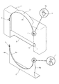
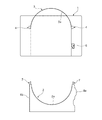
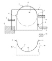
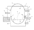
図1は本発明の実施例のファンシュラウドの斜視分解図、図2は同正面図、図3は周辺部材の位置を説明する図、図4は下半部筒体のファンシュラウド本体への装着を説明する図、図5は図4のS5−S5線における断面図、図6は下半部筒体のファンシュラウド本体への装着後を示す平面図、図7は同斜視図である。 1 is an exploded perspective view of a fan shroud according to an embodiment of the present invention, FIG. 2 is a front view of the same, FIG. 3 is a diagram for explaining the positions of peripheral members, and FIG. FIG. 5 is a cross-sectional view taken along line S5-S5 in FIG. 4, FIG. 6 is a plan view showing the lower half cylinder mounted on the fan shroud body, and FIG. 7 is a perspective view thereof.
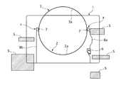
図1、2に示すように、本実施例の熱交換器のファンシュラウドは、ファンシュラウド本体1と下半部筒体2を主要な構成とし、両者はそれぞれ樹脂で一体的に形成されている。
図外のラジエータ側となるファンシュラウド本体1の後面は大きく開口されており、図外のエンジン側となる前面には開口部3aを有する上半部筒体3が形成されている。
前記上半部筒体3の左右下端には、上下方向に開口した開口部4aを有する受け部4,4がそれぞれ形成されている。
前記ファンシュラウド本体1の底面には図外のファンを下方から挿入可能な開口部5が形成されている。
また、ファンシュラウド本体1の前面の右下方には、コ字状断面形状のガイド部6が形成されている。
As shown in FIGS. 1 and 2, the fan shroud of the heat exchanger of the present embodiment has a fan shroud
The rear surface of the
Receiving
An
In addition, a
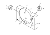
前記下半部筒体2には、上半部筒体3と結合して後述するファンリングRを形成した際に円形状となる半円形状の開口部2aが形成され、左右上端には上方に向かって突出した角柱状の挿入部7,7が形成されている。
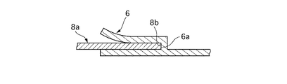
また、前記下半部筒体2の両端縁部にはリム部8a,8bが形成され、両リム部8a,8bのうち、リム部8aは後述する挿入軌跡Kに合致する曲線状に形成され、一方、リム部8bは上下方向に直線状に形成されている。
The lower half
Further,
このように構成された熱交換器のファンシュラウドでは、ファンシュラウド本体1の後面に図外のラジエータが付設された状態で車体のエンジンルームに搭載される。
この際、前記ファンシュラウド本体1の底面の開口部5を介して上半部筒体3の開口部3a内にファンF(図3参照)が収容される。
続いて、下半部筒体2を車体下方から挿入してファンシュラウド本体1に装着するが、この際、図3に示すように、車体側には既に複数の周辺部材Sが設けられているため、下半部筒体2と周辺部材Sが接触する虞がある。
なお、図3中の周辺部材Sはその大まかな位置を示したものであり、実際の周辺部材Sは様々な構造体、補器類、配線等であるためその形状は複雑な形状をしている。
The fan shroud of the heat exchanger thus configured is mounted in the engine room of the vehicle body with a radiator (not shown) attached to the rear surface of the fan shroud
At this time, the fan F (see FIG. 3) is accommodated in the
Subsequently, the lower half
The peripheral member S in FIG. 3 shows the rough position. Since the actual peripheral member S is various structures, auxiliary devices, wirings, etc., the shape thereof is complicated. Yes.
そこで、図4に示すように、先ず、リム部8aの先端をガイド部6に当接した状態で下半部筒体2を配置した後、図5に示すように、リム部8aの側端部8bをガイド部6の側部6aに摺動させながら下半部筒体2をファンシュラウド本体1に対して下方から挿入することにより、下半部筒体2が図4の破線矢印で示す挿入軌跡Kに沿って上方に移動し、これにより下半部筒体2と周辺部材Sとの接触を回避できる。
Therefore, as shown in FIG. 4, first, the lower half
そして、前記下半部筒体2の挿入部7,7を上半部筒体3の受け部4,4の開口部4aにそれぞれ嵌挿固定させることによって、上半部筒体3と下半部筒体2を結合してファンリングRを形成でき、結合部周辺に手を入れることなく短時間で確実に両者を結合できる(図6、7参照)。
Then, by inserting and fixing the
従って、本実施例の熱交換器のファンシュラウドにあっては、リム部8aをガイド部6に摺動させながら下半部筒体2をファンシュラウド本体1に対して下方から挿入するという簡便な作業でもって下半部筒体2をファンシュラウド本体1に短時間で容易かつスムーズに装着でき、この種の熱交換器のファンシュラウドの車体への搭載を良好に行える。
Therefore, in the fan shroud of the heat exchanger of the present embodiment, the lower half
以上、本実施例を説明してきたが、本発明は上述の実施例に限られるものではなく、本発明の要旨を逸脱しない範囲の設計変更等があっても、本発明に含まれる。
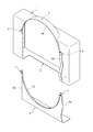
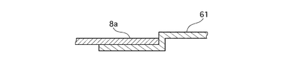
例えば、図8、9に示すように、本実施例で説明したガイド部6を挿入軌跡Kと同様の形状となるように延長させてガイド部60を形成し、リム部8aをガイド部60に摺動させながら下半部筒体2をファンシュラウド本体1に装着させることにより、ガイド部60に下半部筒体2を安定した状態で固定しても良い。また、図10、11に示すように、ガイド部6を階段状に形成したガイド部61を形成してリム部8aとの摺動摩擦を減らすようにしても良い。
Although the present embodiment has been described above, the present invention is not limited to the above-described embodiment, and design changes and the like within a scope not departing from the gist of the present invention are included in the present invention.
For example, as shown in FIGS. 8 and 9, the
また、挿入軌跡Kについては周辺部材Sの形状、位置、形成数によって適宜設定でき、曲線状以外にも直線状、階段状に軌跡を形成する場合もあり得る。 Further, the insertion locus K can be set as appropriate depending on the shape, position, and number of the peripheral members S, and the locus may be formed in a straight line shape or a staircase shape in addition to the curved shape.
さらに、上半部筒体3と下半部筒体2の結合個所、結合位置、結合個所の数についても適宜設定でき、その結合状態については、嵌挿固定以外にも凹凸結合など工具を使用しない嵌合が考えられる。
In addition, the joining location, joining position, and number of joining locations of the
F ファン
S 周辺部材
1 シュラウド本体
2 下半部筒体
2a、3a、4a、5開口部
3 上半部筒体
4 受け部
6 ガイド部
7 挿入部
8a、8b リム部
F Fan S
Claims (2)
前記下半部筒体が、予め車体に搭載された上半部筒体を含むファンシュラウド本体に対して下方から装着される熱交換器のファンシュラウドにおいて、
前記ファンシュラウド本体側にガイド部を形成し、
前記下半部筒体のリム部を、周辺部材を回避するような挿入軌跡に合致する形状に形成し、
前記リム部をガイド部に摺動させながら下半部筒体をファンシュラウド本体に対して下方から装着可能としたことを特徴とする熱交換器のファンシュラウド。 A fan shroud attached to a heat exchanger of an automobile includes a fan ring composed of an upper half cylinder and a lower half cylinder formed so as to surround the fan,
In the fan shroud of the heat exchanger in which the lower half cylinder is mounted from below on the fan shroud main body including the upper half cylinder previously mounted on the vehicle body,
Forming a guide portion on the fan shroud body side;
Forming the rim portion of the lower half cylindrical body in a shape that matches the insertion locus so as to avoid the peripheral members;
A fan shroud of a heat exchanger, characterized in that the lower half cylindrical body can be attached to the fan shroud main body from below while sliding the rim portion on the guide portion.
前記上半部筒体に下方に向かって開口した開口部を有する受け部を形成し、
前記下半部筒体に上方に向かって突出した挿入部を形成すると共に、該挿入部を前記受け部の開口部に嵌挿固定することによって上半部筒体と下半部筒体を結合したことを特徴とする熱交換器のファンシュラウド。 The fan shroud of the heat exchanger according to claim 1,
Forming a receiving portion having an opening that opens downward in the upper half cylinder;
The upper half cylinder and the lower half cylinder are joined by forming an insertion part protruding upward in the lower half cylinder and inserting and fixing the insertion part into the opening of the receiving part. A fan shroud of a heat exchanger characterized by that.
Priority Applications (1)
| Application Number | Priority Date | Filing Date | Title |
|---|---|---|---|
| JP2004104263A JP4313238B2 (en) | 2004-03-31 | 2004-03-31 | Heat exchanger fan shroud |
Applications Claiming Priority (1)
| Application Number | Priority Date | Filing Date | Title |
|---|---|---|---|
| JP2004104263A JP4313238B2 (en) | 2004-03-31 | 2004-03-31 | Heat exchanger fan shroud |
Publications (2)
| Publication Number | Publication Date |
|---|---|
| JP2005291024A true JP2005291024A (en) | 2005-10-20 |
| JP4313238B2 JP4313238B2 (en) | 2009-08-12 |
Family
ID=35324251
Family Applications (1)
| Application Number | Title | Priority Date | Filing Date |
|---|---|---|---|
| JP2004104263A Expired - Fee Related JP4313238B2 (en) | 2004-03-31 | 2004-03-31 | Heat exchanger fan shroud |
Country Status (1)
| Country | Link |
|---|---|
| JP (1) | JP4313238B2 (en) |
Cited By (5)
| Publication number | Priority date | Publication date | Assignee | Title |
|---|---|---|---|---|
| WO2007114070A1 (en) * | 2006-04-04 | 2007-10-11 | Calsonic Kansei Corporation | Heat exchanger for vehicle |
| CN102733924A (en) * | 2012-06-07 | 2012-10-17 | 苏州市奥杰汽车技术有限公司 | Fan cowl device |
| KR20140075484A (en) * | 2012-12-11 | 2014-06-19 | 현대자동차주식회사 | Fan shroud for vehicles |
| JP2016023627A (en) * | 2014-07-24 | 2016-02-08 | ユニキャリア株式会社 | Engine cooling device for industrial vehicles |
| CN113202612A (en) * | 2021-04-27 | 2021-08-03 | 东风马勒热系统有限公司 | Assembled radiator fan guard |
-
2004
- 2004-03-31 JP JP2004104263A patent/JP4313238B2/en not_active Expired - Fee Related
Cited By (6)
| Publication number | Priority date | Publication date | Assignee | Title |
|---|---|---|---|---|
| WO2007114070A1 (en) * | 2006-04-04 | 2007-10-11 | Calsonic Kansei Corporation | Heat exchanger for vehicle |
| CN102733924A (en) * | 2012-06-07 | 2012-10-17 | 苏州市奥杰汽车技术有限公司 | Fan cowl device |
| KR20140075484A (en) * | 2012-12-11 | 2014-06-19 | 현대자동차주식회사 | Fan shroud for vehicles |
| JP2016023627A (en) * | 2014-07-24 | 2016-02-08 | ユニキャリア株式会社 | Engine cooling device for industrial vehicles |
| CN113202612A (en) * | 2021-04-27 | 2021-08-03 | 东风马勒热系统有限公司 | Assembled radiator fan guard |
| CN113202612B (en) * | 2021-04-27 | 2022-06-03 | 东风马勒热系统有限公司 | Assembled radiator fan guard |
Also Published As
| Publication number | Publication date |
|---|---|
| JP4313238B2 (en) | 2009-08-12 |
Similar Documents
| Publication | Publication Date | Title |
|---|---|---|
| US7731241B2 (en) | Assembly for fitting together exhaust pipes in multi-cylinder engine | |
| JP4258529B2 (en) | Wire harness protector | |
| JP4313238B2 (en) | Heat exchanger fan shroud | |
| JP2007531849A (en) | Plug-in connection with fixed angular position | |
| JP2009071932A (en) | Joint holder | |
| JP2009203901A (en) | Installing structure of air intake component | |
| JP2016020163A (en) | Attachment structure of filler pipe | |
| US8203076B2 (en) | Electrical junction box | |
| JP4636907B2 (en) | Intake manifold | |
| JP2006321317A (en) | Vehicular air guide structure | |
| JP2006266089A (en) | Piping structure of radiator core support | |
| JP2006102750A (en) | Keren and its mounting structure | |
| JP6504038B2 (en) | Pillar garnish mounting structure and tether clip | |
| JP6516479B2 (en) | Connection structure of vehicle lamp parts | |
| US20180202345A1 (en) | Method for molding pipe body | |
| JP2010254019A (en) | Vehicular air-conditioning blow-duct connecting structure | |
| JP2011020533A (en) | Attachment structure of front grille | |
| JP7243502B2 (en) | Grommet | |
| JP3711926B2 (en) | Front end module structure for vehicle and method for assembling front end module | |
| JP2000234520A (en) | Fan shroud | |
| JP2014131890A (en) | Combined structure of front pillar trim and instrument panel | |
| KR20040060143A (en) | Front End Module Carrier of a Vehicle and Method of Fabrication therefor | |
| KR200439802Y1 (en) | Adjustable connector cover | |
| KR20090062160A (en) | Vehicle fog lamp and bracket mounting structure | |
| JP2006015906A (en) | Bumper structure |
Legal Events
| Date | Code | Title | Description |
|---|---|---|---|
| RD04 | Notification of resignation of power of attorney |
Free format text: JAPANESE INTERMEDIATE CODE: A7424 Effective date: 20051115 |
|
| A621 | Written request for application examination |
Free format text: JAPANESE INTERMEDIATE CODE: A621 Effective date: 20060324 |
|
| A977 | Report on retrieval |
Free format text: JAPANESE INTERMEDIATE CODE: A971007 Effective date: 20090129 |
|
| A131 | Notification of reasons for refusal |
Free format text: JAPANESE INTERMEDIATE CODE: A131 Effective date: 20090203 |
|
| A521 | Written amendment |
Free format text: JAPANESE INTERMEDIATE CODE: A523 Effective date: 20090326 |
|
| TRDD | Decision of grant or rejection written | ||
| A01 | Written decision to grant a patent or to grant a registration (utility model) |
Free format text: JAPANESE INTERMEDIATE CODE: A01 Effective date: 20090512 |
|
| A01 | Written decision to grant a patent or to grant a registration (utility model) |
Free format text: JAPANESE INTERMEDIATE CODE: A01 |
|
| A61 | First payment of annual fees (during grant procedure) |
Free format text: JAPANESE INTERMEDIATE CODE: A61 Effective date: 20090514 |
|
| FPAY | Renewal fee payment (prs date is renewal date of database) |
Free format text: PAYMENT UNTIL: 20120522 Year of fee payment: 3 |
|
| R150 | Certificate of patent (=grant) or registration of utility model |
Free format text: JAPANESE INTERMEDIATE CODE: R150 |
|
| FPAY | Renewal fee payment (prs date is renewal date of database) |
Free format text: PAYMENT UNTIL: 20130522 Year of fee payment: 4 |
|
| FPAY | Renewal fee payment (prs date is renewal date of database) |
Free format text: PAYMENT UNTIL: 20130522 Year of fee payment: 4 |
|
| FPAY | Renewal fee payment (prs date is renewal date of database) |
Free format text: PAYMENT UNTIL: 20140522 Year of fee payment: 5 |
|
| R250 | Receipt of annual fees |
Free format text: JAPANESE INTERMEDIATE CODE: R250 |
|
| LAPS | Cancellation because of no payment of annual fees |