JP2005291015A - Scroll blower - Google Patents
Scroll blower Download PDFInfo
- Publication number
- JP2005291015A JP2005291015A JP2004103795A JP2004103795A JP2005291015A JP 2005291015 A JP2005291015 A JP 2005291015A JP 2004103795 A JP2004103795 A JP 2004103795A JP 2004103795 A JP2004103795 A JP 2004103795A JP 2005291015 A JP2005291015 A JP 2005291015A
- Authority
- JP
- Japan
- Prior art keywords
- scroll
- sound
- blower
- wrap
- fixed
- Prior art date
- Legal status (The legal status is an assumption and is not a legal conclusion. Google has not performed a legal analysis and makes no representation as to the accuracy of the status listed.)
- Withdrawn
Links
Images


Landscapes
- Rotary Pumps (AREA)
- Applications Or Details Of Rotary Compressors (AREA)
Abstract
Description
本発明は、一般に工業用に使用される空気供給手段や汚泥処理装置における空気供給手段、燃料電池発電装置における酸素供給の目的で使用されるスクロール送風機に関するものである。 The present invention relates to an air supply means generally used for industrial use, an air supply means in a sludge treatment apparatus, and a scroll blower used for the purpose of supplying oxygen in a fuel cell power generation apparatus.
従来、この種のスクロール送風機は回転軸とモータ軸がカップリング等の結合手段100で連結されており、吸込口はスクロール部から比較的近くの円周方向に設置されたものが知られている。 Conventionally, this type of scroll blower is known in which a rotating shaft and a motor shaft are connected by a coupling means 100 such as a coupling, and a suction port is installed in a circumferential direction relatively close to the scroll portion. .
以下、そのスクロール送風機について図7を参照しながら説明する。 Hereinafter, the scroll blower will be described with reference to FIG.
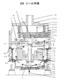
固定スクロール部材101は固定スクロールラップ102、固定ラップ支持板103及び吸込口104を備えたケーシング105と一体形状となっており、フレーム106に固定ボルトで固定支持されている。公転スクロール部材107は公転スクロールラップ108、公転ラップ支持板109及び公転スクロールボス部110と一体形状になっており、公転スクロールラップ108は固定スクロールラップ102に対して噛み合い、密閉空間が作られるようになっている。更に公転ラップ支持板109とボス部110は、軸受E91、112を介して回転軸113より所定量偏心した偏心軸部114に、回転自在に支持されている。公転スクロールボス部110の吐出側には漏れ防止手段115を設け、空気洩れを防ぐ構造となっているので圧縮された気体は吐出口116へ吐出される。
一般にスクロール機構を用いたスクロール送風機は気体圧縮室によって圧縮された気体が吐出の際に一気に開放される為、気体圧縮室を形成するスクロール部から回転数に起因した脈動音が発生するために特に吸込口や部品精度誤差や表面粗さによってできる隙間から脈動音が放射することによる騒音が大きいという課題があり、より低騒音のスクロール送風機が要求されている。 In general, a scroll blower using a scroll mechanism is released at once when the gas compressed by the gas compression chamber is discharged, so that a pulsating sound caused by the rotation speed is generated from the scroll portion forming the gas compression chamber. There is a problem that noise caused by pulsation noise is radiated from a gap formed by a suction port, parts accuracy error, and surface roughness, and a scroll fan with lower noise is required.
本発明は、このような従来の課題を解決するものであり、スクロール部から発生する脈動音を外部に放射する前に低減することにより、低騒音のスクロール送風機を提供することを目的としている。 The present invention solves such a conventional problem, and an object of the present invention is to provide a low-noise scroll blower by reducing the pulsating sound generated from the scroll portion before radiating it to the outside.
本発明のスクロール送風機は、上記目標を達成するため吸込口設置箇所を軸方向に回転軸終端より外側に設置し、且つクランク軸支持部あるいはモータ支持部を形成する面に少なくとも一箇所以上の孔を設置して吸込風路を形成することを特徴とする。そして、本発明によれば脈動音が発生するスクロール部から離れた位置に吸込口を設けることで脈動音を距離減衰させ、且つ前記クランク軸支持部あるいはモータ支持部を形成する面に遮音の役割をさせることにより騒音を軽減することができるスクロール送風機が得られる。 In order to achieve the above-mentioned target, the scroll blower of the present invention is provided with the suction port installation location in the axial direction outside the end of the rotary shaft, and at least one hole in the surface forming the crankshaft support portion or the motor support portion. And a suction air passage is formed. According to the present invention, the suction port is provided at a position away from the scroll portion where the pulsation noise is generated to attenuate the pulsation sound by a distance, and the surface of the crankshaft support portion or the motor support portion forms a sound insulating role. By doing so, a scroll blower capable of reducing noise can be obtained.
また、スクロール送風機に外装体を備え、前記外装体の内側もしくは回転軸に対して半径方向に形成された面に吸音材を備えたことにより、脈動音をより効率良く減衰させることができるスクロール送風機が得られる。 Also, the scroll blower can be more efficiently attenuated by providing a scroll blower with an exterior body and a sound absorbing material on the inside of the exterior body or a surface formed in a radial direction with respect to the rotation axis. Is obtained.
また、吸込口近傍に遮音板を設置したことにより、スクロール部から発生する脈動音が吸込口から外部への直接放射を抑制することができるスクロール送風機が得られる。 Moreover, by installing the sound insulation board in the vicinity of the suction port, it is possible to obtain a scroll blower in which pulsation sound generated from the scroll portion can suppress direct radiation from the suction port to the outside.
また、スクロール送風機に複数の外装体を備え、前記外装体の接合部分についてシール手段を設置することにより、スキマから外部に漏れる騒音を削減することができることができるスクロール送風機が得られる。 Moreover, the scroll blower which can reduce the noise which leaks outside from a clearance gap is provided by providing a scroll blower with a some exterior body and installing a sealing means about the junction part of the said exterior body.
本発明によれば、吸込口設置箇所を軸方向に回転軸終端より外側に設置し、且つクランク軸支持部あるいはモータ支持部を形成する面に少なくとも一箇所以上の孔を設置して吸込風路を形成することにより脈動音が発生するスクロール部分から離れた位置に吸込口を設けることで、距離により音を減衰させることができ、且つクランク軸支持部あるいはモータ支持部を形成する面に少なくとも一箇所以上の孔を設置することにより、音漏れ防止という遮音効果を利用できることから外部に漏れる騒音を軽減することができるという効果のあるスクロール送風機を提供できる。 According to the present invention, the suction port installation location is installed outside the end of the rotary shaft in the axial direction, and at least one hole is provided on the surface forming the crankshaft support portion or the motor support portion. By providing the suction port at a position away from the scroll portion where the pulsating noise is generated, the sound can be attenuated by the distance, and at least one of the surfaces forming the crankshaft support portion or the motor support portion can be provided. Since the sound insulation effect of preventing sound leakage can be used by installing more holes, a scroll blower that has an effect of reducing noise leaking to the outside can be provided.
また、孔を複数設けた場合、孔位置が回転軸方向に対して重ならないように配置したことによりスクロール部から発生する脈動音の直接放射を防ぎ、遮音効果を一層高めることができるという効果のあるスクロール送風機を提供できる。 In addition, when a plurality of holes are provided, by arranging the hole positions so as not to overlap with the rotation axis direction, direct emission of pulsating sound generated from the scroll portion can be prevented, and the sound insulation effect can be further enhanced. Some scroll blowers can be provided.
また、スクロール送風機に外装体を備え、前記外装体の内側もしくは回転軸に対して半径方向に形成された面に吸音材を備えたことにより、音エネルギーを熱エネルギーに変換して騒音を低減させ、外部に漏れる騒音を軽減できるという効果のあるスクロール送風機を提供できる。 In addition, the scroll blower is provided with an exterior body, and a sound absorbing material is provided on the inner surface of the exterior body or a surface formed in a radial direction with respect to the rotation axis, thereby reducing sound by converting sound energy into heat energy. It is possible to provide a scroll blower that is effective in reducing noise leaking to the outside.
また、吸込口近傍に遮音板を設置したことにより、スクロール部分から発生する脈動音が開口部から外部への直接放射を抑制し、外部へもれる騒音を軽減できるという効果のあるスクロール送風機を提供できる。 In addition, by installing a sound insulation board near the suction port, a scroll blower that has the effect of suppressing the direct radiating from the opening to the outside due to the pulsating sound generated from the scroll part and reducing the noise leaking to the outside is provided. it can.
また、スクロール送風機に複数の外装体を備え、前記外装体の接合部分についてシール手段を設置することにより、前記接合部分について部品精度誤差や表面粗さによる微小なスキマを塞ぐ構成とすることで外部に漏れる騒音を軽減できるという効果のあるスクロール送風機を提供できる。 Further, the scroll blower is provided with a plurality of exterior bodies, and by installing sealing means for the joint portion of the exterior body, the joint portion is configured to block minute gaps due to component accuracy errors and surface roughness. It is possible to provide a scroll blower having an effect of reducing noise leaking into the fan.
本発明の請求項1記載の発明は、吸込口設置箇所を軸方向に回転軸終端より外側に設置することで、脈動音が発生するスクロール部分から離れた位置に吸込口を設けることが可能となり、距離により音を減衰させることができ、且つクランク軸支持部あるいはモータ支持部を形成する面に少なくとも一箇所以上の孔を設置して吸込風路を形成することにより、遮音効果を利用できるという作用を有する。
In the invention according to
また、孔を複数設けた場合、孔位置が回転軸方向に対して重ならないように配置したことによりスクロール部から発生する脈動音の直接放射を防ぎ、遮音効果を一層高める作用を有する。 Further, when a plurality of holes are provided, the holes are arranged so that the positions of the holes do not overlap with the rotation axis direction, thereby preventing direct emission of the pulsating sound generated from the scroll portion and further enhancing the sound insulation effect.
また、スクロール送風機に外装体を備え、前記外装体の内側もしくは回転軸に対して半径方向に形成された面に吸音材を備えたことにより、音エネルギーを熱エネルギーに変換する作用を有する。 Further, the scroll blower is provided with an exterior body, and the sound absorbing material is provided on the inner surface of the exterior body or a surface formed in the radial direction with respect to the rotation axis, thereby having an effect of converting sound energy into heat energy.
また、吸込口近傍に遮音板を設置したことにより、スクロール部分から発生する脈動音が吸込口から外部への直接放射を抑制する作用を有する。 In addition, since the sound insulating plate is installed in the vicinity of the suction port, the pulsation sound generated from the scroll portion has an action of suppressing direct radiation from the suction port to the outside.
また、スクロール送風機に複数の外装体を備え、前記外装体の接合部分についてシール手段を設置することにより、前記接合部分について部品精度誤差や表面粗さによる微小なスキマを塞ぐ構成とすることで外部に漏れる音を防ぐという作用を有する。 Further, the scroll blower is provided with a plurality of exterior bodies, and by installing sealing means for the joint portion of the exterior body, the joint portion is configured to block minute gaps due to component accuracy errors and surface roughness. It has the effect of preventing sound leaking into the water.
以下、本発明の実施の形態について図面を参照しながら説明する。 Hereinafter, embodiments of the present invention will be described with reference to the drawings.
(実施の形態1)
従来例と同一部分は同一番号を附し、詳細な説明は省略する。
(Embodiment 1)
The same parts as those in the conventional example are denoted by the same reference numerals, and detailed description thereof is omitted.
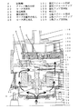
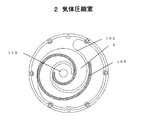
図1に示すように、固定スクロール部材101としての羽根は片面に渦巻状の固定スクロールラップ102と固定ラップ支持板103と吐出口116が一体となっており、固定部材1としての金属製支持体に固定ボルトで固定されている。公転スクロール部材107としての羽根は片面に渦巻状の公転スクロールラップ108と公転ラップ支持板109が一体形状となっており、公転スクロールラップ108は、固定スクロールラップ102に対して図2のように噛み合っている。このとき、固定スクロールラップ102と公転スクロールラップ108について端面と側面は微少隙間を保持した状態で気体圧縮室2を形成することにより、非接触で機械損失のない送風を実現している。
As shown in FIG. 1, the
送風メカニズムとしては、公転スクロールラップ108を時計周りに公転させることで、気体圧縮室2が順次外側から内側に移動し圧縮されて、固定ラップ支持板103の吐出口116から気体が吐出する構造となっていることから、気体圧縮室2で圧縮された気体を一気に開放する際に圧力変動が発生し、回転数に起因した脈動音がスクロール部から発生してしまう。
As the air blowing mechanism, by revolving the revolving
公転スクロール部材107は、遠心力を小さくする為に質量の小さなPPS、液晶ポリマー、ABS、変性PPOまたは、気泡の混入した軽量な合成樹脂材料で作られており、公転スクロールラップ108の反対側に、アルミニウム合金系、鉄合金系及びチタン合金等の材質で公転円盤3を設け、公転円盤3に公転ラップ支持板109に設置された複数個の取り付けボスのねじ穴に固定ボルトで連結されている。また、公転円盤3は回転軸4の偏心軸部5が軸受A4を介して回転自在に固定され、回転軸4と同じ偏心量を持った2個以上のクランクピン5の一方に軸受B6を介して回転自在に固定され、もう一方は軸受C7を介して固定部材1に回転自在に支持されている。
The
このとき、固定部材1に具備された軸受D8とステ−タに具備された軸受E9によって支持された回転軸4にロータ10の回転力が偏心軸部5の軸受A4を介して公転運動を伝達し、公転円盤3が公転して且つ自転しようとするが、2個以上のクランクピン5が同期して回転することにより公転円盤3は自転を防止され、振れのない公転運動を実現している。
At this time, the rotational force of the
回転軸4には、2つのバランスウェートA11、バランスウェートB12が設置されており、偏心軸部5に近い方は偏心軸と反対の角度に設置され、偏心軸部5から遠い方は偏心軸部5と同じ角度に設置することにより、公転スクロール部材107が公転する際に発生する遠心力を打ち消している。
The rotating
モータ位置決め板13は、固定部材1に支柱14で固定されており、中心部穴とステータ15が勘合することによりステータ15を半径方向に位置決め固定し、モータ押え板16でステータ15端面をモータ位置決め板13に押付けることによってステータ15を軸方向に位置決めしている。
The motor positioning plate 13 is fixed to the
モータ押え板16は、支柱14の高さをステータ15高さに対して低くすることにより、モータ押え板16を支柱14に固定ねじで締付けた際にステータ15を押付ける力を発生させている。また、ステータ15より外側にリング17を設けることにより内部と外部を隔離する役割を果たしている。このとき、リング17の高さをステータ15高さより低く、支柱14より高くすることにより、ステータ15と同様にリング17をモータ押え板16でモータ位置決め板13に押付けることによって固定している。
The
カバー18は取付足19とモータ支持部22とを具備し、モータ押え板16に固定ボルトで固定されている。
The
取付足19の一部はゴム質となっており、振動防止の役目を果たしている。
A part of the mounting
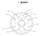
上記構成において、吸込口設置箇所を軸方向に回転軸4終端より外側であるカバー18に設置することで、脈動音が発生するスクロール部分から最も離れた位置に吸込口104を設けることが可能となり、距離により音を減衰させることができる。且つ回転軸4に対して半径方向に形成されたクランク軸支持部21とモータ支持部22を形成する面を備えた固定部材1とモータ位置決め板13とモータ押え板16について単数もしくは複数の孔を設置して吸込風路23を形成することによりスクロール部で発生する脈動音が吸込口104まで到達するまでに遮音効果があり、外部に漏れる騒音を軽減できる。
In the above configuration, the
回転軸4に対して半径方向に形成されたクランク軸支持部21、モータ支持部22については、遮音の効果を上げる為にアルミ合金、鉄、ステンレス等、密度の高い金属で製作すると遮音効果が高い。また、孔の大きさとしては、遮音効果があり圧力損失を最小限とすることで性能を損なわず脈動音が放射する騒音を軽減することができる。
If the
(実施の形態2)
従来例または実施の形態1と同一部分は同一番号を附し、詳細な説明は省略する。孔を複数設けた場合、回転軸4に対して半径方向に形成された面を有する固定部材1とモータ位置決め板13とモータ押え板16について、図3のように、固定部材1に設けた固定部材孔24とモータ位置決め板13に設けたモータ位置決め板孔25とモータ押え板16に設けたモータ押え板孔26が回転軸4方向に対して重ならない、すなわち回転軸4と平行な一直線とならないように配置したことによりスクロール部から発生する脈動音がカバー18に設置された吸込口104へ直接放射していくことが防止でき、遮音効果を一層高めることで外部に漏れる騒音をより効率良く軽減できる。
(Embodiment 2)
The same parts as those in the conventional example or the first embodiment are denoted by the same reference numerals, and detailed description thereof is omitted. When a plurality of holes are provided, the fixing
(実施の形態3)
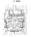
従来例または実施の形態1あるいは2と同一部分は同一番号を附し、詳細な説明は省略する。図4のように、スクロール送風機に外装体を備え、前記外装体の内側もしくは回転軸に対して半径方向に形成された面を有する、例えば固定スクロール部材101、固定部材1、モータ位置決め板13、リング17、モータ押え板16、カバー18について外装面の内側もしくは回転軸4に対して半径方向に形成された面に吸音材27を貼り付けることにより、スクロール部から発生する脈動音の音エネルギーを熱エネルギーに変換でき、吸込口104から放射する前に減衰させることができるので、騒音を軽減することができる。主な吸音材27としては、多孔質材やウレタンフォームを使用するのが好ましい。
(Embodiment 3)
The same parts as those in the conventional example or the first or second embodiment are denoted by the same reference numerals, and detailed description thereof is omitted. As shown in FIG. 4, the scroll blower includes an exterior body, and has a surface formed in the radial direction with respect to the inner side or the rotation axis of the exterior body, for example, the fixed
(実施の形態4)
従来例または実施の形態1から3のいずれかと同一部分は同一番号を附し、詳細な説明は省略する。図5に示すように、吸込口104の直後に遮音板28を設置したことにより、スクロール部から発生する脈動音が吸込口104から外部への直接放射を抑制させ、騒音を軽減することができる。ただし、遮音板28と吸込口104との距離については、吸込風路の妨げとならない、すなわち圧力損失とならない程度としなければならない。なお、遮音板28の材質は遮音の効果を上げる為にアルミ合金、鉄、ステンレス等、密度の高い金属で製作するのが望ましい。また、吸込口近傍とは、吸込口の内側または外側を意味しており、遮音板28は吸込口104の直前に設置したとしても同様の効果が得られる。
(Embodiment 4)
The same parts as those in the conventional example or any of
(実施の形態5)
従来例または実施の形態1から4のいずれかと同一部分は同一番号を附し、詳細な説明は省略する。図6に示すように、スクロール送風機に複数の外装体を備えた固定スクロール部材101、固定部材1、モータ位置決め板13、リング17、モータ押え板16、カバー18との接合面にシール手段29を設置することにより、前記接合面について部品精度誤差や表面粗さによる微小なスキマを塞ぐ構成とすることで外部に漏れる音を防ぐことで騒音を軽減することができる。
(Embodiment 5)
The same parts as those of the conventional example or any of
その際のシール手段29としては、前記接合面にガスケットを設置する、化学系接着材を接合面に塗布する、ゴムを設置するなど、スキマを埋める為に何らかの処置を施しても良いし、接合面をインローにして勘合部を設けることによりスキマをできる限り無くす手段としてもよい。 As the sealing means 29 at that time, some measures may be taken to fill the gap, such as placing a gasket on the joining surface, applying a chemical adhesive to the joining surface, or installing rubber. It is good also as a means which eliminates a clearance gap as much as possible by providing a fitting part by making a surface inlay.
本発明にかかるスクロール送風機は、一般に工業用に使用される空気供給手段や汚泥処理装置における空気供給手段、燃料電池発電装置における酸素供給の目的で使用される送風機として低騒音化を実現するスクロール送風機として有効である。 The scroll blower according to the present invention is a scroll blower that achieves low noise as an air supply means generally used for industrial use, an air supply means in a sludge treatment apparatus, and a blower used for oxygen supply in a fuel cell power generation apparatus. It is effective as
1 固定部材
2 気体圧縮室
4 回転軸
21 クランク軸支持部
22 モータ支持部
23 吸込風路
24 固定部材孔
25 モータ位置決め板孔
26 モータ押え板孔
27 吸音材
28 遮音板
29 シール手段
101 固定スクロール部材
102 固定スクロールラップ
103 固定ラップ支持板
104 吸込口
107 公転スクロール部材
108 公転スクロールラップ
109 公転ラップ支持板
DESCRIPTION OF
Claims (8)
Priority Applications (1)
| Application Number | Priority Date | Filing Date | Title |
|---|---|---|---|
| JP2004103795A JP2005291015A (en) | 2004-03-31 | 2004-03-31 | Scroll blower |
Applications Claiming Priority (1)
| Application Number | Priority Date | Filing Date | Title |
|---|---|---|---|
| JP2004103795A JP2005291015A (en) | 2004-03-31 | 2004-03-31 | Scroll blower |
Publications (1)
| Publication Number | Publication Date |
|---|---|
| JP2005291015A true JP2005291015A (en) | 2005-10-20 |
Family
ID=35324243
Family Applications (1)
| Application Number | Title | Priority Date | Filing Date |
|---|---|---|---|
| JP2004103795A Withdrawn JP2005291015A (en) | 2004-03-31 | 2004-03-31 | Scroll blower |
Country Status (1)
| Country | Link |
|---|---|
| JP (1) | JP2005291015A (en) |
Cited By (4)
| Publication number | Priority date | Publication date | Assignee | Title |
|---|---|---|---|---|
| WO2014179098A1 (en) * | 2013-04-29 | 2014-11-06 | United Technologies Corporation | Fuel cell system blower configuration |
| CN111365233A (en) * | 2018-12-25 | 2020-07-03 | 株式会社石川能源研究 | scroll compressor |
| CN113356293A (en) * | 2021-05-17 | 2021-09-07 | 柯丽君 | Energy-saving motor pump based on lake treatment |
| JP7524837B2 (en) | 2021-06-21 | 2024-07-30 | 株式会社デンソー | Fluid Machinery |
-
2004
- 2004-03-31 JP JP2004103795A patent/JP2005291015A/en not_active Withdrawn
Cited By (6)
| Publication number | Priority date | Publication date | Assignee | Title |
|---|---|---|---|---|
| WO2014179098A1 (en) * | 2013-04-29 | 2014-11-06 | United Technologies Corporation | Fuel cell system blower configuration |
| US9831510B2 (en) | 2013-04-29 | 2017-11-28 | Audi Ag | Fuel cell system blower configuration |
| CN111365233A (en) * | 2018-12-25 | 2020-07-03 | 株式会社石川能源研究 | scroll compressor |
| CN113356293A (en) * | 2021-05-17 | 2021-09-07 | 柯丽君 | Energy-saving motor pump based on lake treatment |
| CN113356293B (en) * | 2021-05-17 | 2022-07-29 | 苏州赛荣建筑装饰工程有限公司 | Energy-saving motor pump based on lake treatment |
| JP7524837B2 (en) | 2021-06-21 | 2024-07-30 | 株式会社デンソー | Fluid Machinery |
Similar Documents
| Publication | Publication Date | Title |
|---|---|---|
| US20080159888A1 (en) | fluid machine connected to a drive source via a magnetic coupling | |
| US20160305431A1 (en) | Compact low noise rotary compressor | |
| JP5769332B2 (en) | Scroll expander | |
| US9989058B2 (en) | Electric motor vehicle vacuum pump arrangement | |
| JP2020033875A (en) | Compression device | |
| US9777601B2 (en) | Muffler and muffling device including the same | |
| JPH0893693A (en) | Turbo fluid machinery | |
| KR102271438B1 (en) | Soundproof cover of a compressor | |
| CN201241828Y (en) | Vacuum pump | |
| CN101312640A (en) | heat sink | |
| JP2005291015A (en) | Scroll blower | |
| JP5457943B2 (en) | Scroll type fluid machine | |
| JP2012167606A (en) | Turbo machine | |
| JP5295087B2 (en) | Scroll compressor | |
| JP7219114B2 (en) | Rotating electric machine | |
| JP2015001175A (en) | Scroll type fluid machine | |
| JP2008514862A (en) | Friction vacuum pump | |
| JP2002371977A (en) | Scroll fluid machine | |
| JP2003343495A (en) | Noise reduction device for compressor unit | |
| JPH1037885A (en) | Compressor and compressor manufacturing method | |
| KR101871385B1 (en) | Scroll compressor | |
| JP2002317777A (en) | Scroll fluid machine | |
| JP2002089486A (en) | Water pump | |
| JP5455676B2 (en) | Scroll type fluid machine | |
| CN113227584A (en) | Pump and method of operating the same |
Legal Events
| Date | Code | Title | Description |
|---|---|---|---|
| A621 | Written request for application examination |
Free format text: JAPANESE INTERMEDIATE CODE: A621 Effective date: 20061117 |
|
| RD01 | Notification of change of attorney |
Free format text: JAPANESE INTERMEDIATE CODE: A7421 Effective date: 20061213 |
|
| A761 | Written withdrawal of application |
Free format text: JAPANESE INTERMEDIATE CODE: A761 Effective date: 20081120 |