JP2005291003A - Odd-form wire rod with groove for two-piece type oil ring - Google Patents
Odd-form wire rod with groove for two-piece type oil ring Download PDFInfo
- Publication number
- JP2005291003A JP2005291003A JP2004103148A JP2004103148A JP2005291003A JP 2005291003 A JP2005291003 A JP 2005291003A JP 2004103148 A JP2004103148 A JP 2004103148A JP 2004103148 A JP2004103148 A JP 2004103148A JP 2005291003 A JP2005291003 A JP 2005291003A
- Authority
- JP
- Japan
- Prior art keywords
- oil ring
- width
- groove
- wire rod
- rail portion
- Prior art date
- Legal status (The legal status is an assumption and is not a legal conclusion. Google has not performed a legal analysis and makes no representation as to the accuracy of the status listed.)
- Pending
Links
- 238000002485 combustion reaction Methods 0.000 abstract description 5
- 239000003921 oil Substances 0.000 description 29
- 238000000034 method Methods 0.000 description 6
- 238000004080 punching Methods 0.000 description 3
- 238000007790 scraping Methods 0.000 description 3
- 229910000831 Steel Inorganic materials 0.000 description 1
- 238000000137 annealing Methods 0.000 description 1
- 230000003811 curling process Effects 0.000 description 1
- 230000001788 irregular Effects 0.000 description 1
- 239000010687 lubricating oil Substances 0.000 description 1
- 229910001105 martensitic stainless steel Inorganic materials 0.000 description 1
- 239000000463 material Substances 0.000 description 1
- 238000005121 nitriding Methods 0.000 description 1
- 238000010791 quenching Methods 0.000 description 1
- 230000000171 quenching effect Effects 0.000 description 1
- 238000005096 rolling process Methods 0.000 description 1
- 239000010959 steel Substances 0.000 description 1
- 238000005496 tempering Methods 0.000 description 1
Images
Landscapes
- Pistons, Piston Rings, And Cylinders (AREA)
Abstract
Description
本発明は、各種内燃機関のピストンのリング溝に装着する2ピース型オイルリング(以下、単にオイルリングという)に用いる溝付異形線材に関し、特に幅と厚さが2mm以下であるオイルリングに適した溝付異形線材に関する。 The present invention relates to a grooved deformed wire used for a two-piece oil ring (hereinafter simply referred to as an oil ring) to be mounted in a ring groove of a piston of various internal combustion engines, and is particularly suitable for an oil ring having a width and thickness of 2 mm or less. The present invention relates to a deformed wire rod having a groove.
一般に、この種オイルリング用溝付異形線材は、硬鋼線材をロールやダイスによる塑性加工により断面略H字型に成形した後、打ち抜き加工によって線材長手方向のウェブ部に多数の油孔を直列状に形成している。そして、この溝付異形線材を用いて、ピストンリングメーカでは、カーリング加工と研削加工により所要のオイルリングを成形している。上記カーリング加工は溝付異形線材を所要の呼び径と自由合口すきまを有するリング状に成形する加工であり、その後の研削加工は、ピストンのリング溝に接する面となるリング体の上下面を平行化する加工である。 In general, this kind of grooved deformed wire rod for oil ring is formed by forming a hard steel wire rod into a substantially H-shaped section by plastic working with a roll or a die, and then connecting a number of oil holes in the web portion in the longitudinal direction of the wire rod by punching. It is formed in a shape. Then, using this grooved deformed wire, a piston ring manufacturer forms a required oil ring by curling and grinding. The curling process is a process of forming a grooved deformed wire into a ring shape having a required nominal diameter and a free joint clearance, and the subsequent grinding process is performed by paralleling the upper and lower surfaces of the ring body that will be in contact with the ring groove of the piston. It is processing to turn into.
従来、この種オイルリングは、トラック、バス等のディーゼルエンジンに使用され、幅B×厚さTが(3.5〜5.0)mm×(2.5〜3.0)mmである断面寸法の大きいものであった。近年、オイルリングは、小型の内燃機関(ディーゼルエンジンやガソリンエンジン)にも使用され始め、断面寸法の小さいものが必要になり、これに適した溝付異形線材が求められている。 Conventionally, this kind of oil ring is used for diesel engines such as trucks and buses, and has a cross section of width B × thickness T (3.5 to 5.0) mm × (2.5 to 3.0) mm. The size was large. In recent years, oil rings have begun to be used for small internal combustion engines (diesel engines and gasoline engines), and those having a small cross-sectional dimension are required, and there is a demand for a grooved deformed wire suitable for this.
そこで、この要求に応えるため、未研磨仕上状態で、幅Bを3.0mm以下、高さ(厚さT)を2.3mm以下とし、線材の長手方向にわたる幅寸法のバラツキを0.015mm以下にしたオイルリングが提案されている(例えば、特許文献1)。
特許文献1は、幅B×高さ(厚さT)が3.0mm×2.3mm程度以下の小断面材では、その断面形状が油孔の打ち抜き加工によって乱れるため、ピストンリングメーカでの研削加工に手数を要し、生産性が低下することに鑑みてなされたものである。
According to
ところで、オイルリングは、エンジンの高性能化、軽量化のため、断面寸法がさらに小さいものが求められている。しかし、従来技術によると、断面寸法が小さい(幅Bと厚さTが2.00mm以下)溝付異形線材になると、ピストンリングメーカでの研削加工によって、レール部の先端隅部が研削されて摺動面の幅が狭くなり、潤滑油の掻き落とし能力を十分に発揮するオイルリングを成型することができないことが判明した。 By the way, the oil ring is required to have a smaller cross-sectional dimension in order to improve the performance and weight of the engine. However, according to the prior art, when the profiled wire with groove is small (width B and thickness T is 2.00 mm or less), the tip corner of the rail portion is ground by grinding at the piston ring manufacturer. It turned out that the width of the sliding surface was narrowed, and an oil ring that sufficiently exhibited the ability to scrape off the lubricating oil could not be molded.
そこで、本発明は、幅Bと厚さTが2mm以下、具体的には、幅Bが1.50〜1.55mm、厚さTが1.50〜2.00mmであり、小型の内燃機関に適したオイルリングを成形し得る溝付異形線材を提供することを課題とする。 Accordingly, the present invention provides a small-sized internal combustion engine having a width B and a thickness T of 2 mm or less, specifically, a width B of 1.50 to 1.55 mm and a thickness T of 1.50 to 2.00 mm. It is an object of the present invention to provide a grooved deformed wire that can form an oil ring suitable for the above.
本発明は、幅Bと厚さTが2.00mm以下であり、かつウェブ部に油孔を直列状に連設したオイルリング用溝付異形線材であって、ピストンのリング溝に接する面を平行化する研削加工によって、レール部摺動面の幅が減少されないようにしたことを特徴とする。 The present invention is an oil ring grooved deformed wire having a width B and a thickness T of 2.00 mm or less, and oil holes provided in series in a web portion, and has a surface in contact with a ring groove of a piston. The width of the rail portion sliding surface is not reduced by the parallel grinding process.
本発明において、研削加工時によって、レール部摺動面の幅が減少されないようにする具体的手段としては、ピストンのリング溝に接する面となる両側面の延長した基準線とレール部の外側隅部との間隔Cをそれぞれ少なくとも0.08mmにすることにより達成される。より具体的には、レール部摺動面の幅Dを0.13〜0.19mmの範囲にし、レール部の内側傾斜角度θが3〜7°の範囲にすることにより達成することができる。この場合、レール部の外側傾斜面の下端と側面上端とを段部を介して接続した構成にするとより好適である。 In the present invention, specific means for preventing the width of the sliding surface of the rail portion from being reduced during grinding is as follows: an extended reference line on both side surfaces that are in contact with the ring groove of the piston and an outer corner of the rail portion. This is achieved by setting the distance C between each part to at least 0.08 mm. More specifically, this can be achieved by setting the width D of the sliding surface of the rail portion to be in the range of 0.13 to 0.19 mm and the inner inclination angle θ of the rail portion to be in the range of 3 to 7 °. In this case, it is more preferable that the lower end of the outer inclined surface of the rail portion and the upper end of the side surface are connected via a stepped portion.
本発明のオイルリング用溝付異形線材によるときは、幅Bが1.50〜1.55mm、厚さTが1.50〜2.00mmであり、小型の内燃機関に適したオイルリングを得ることができる。 When the profiled wire rod for oil ring of the present invention is used, the width B is 1.50 to 1.55 mm and the thickness T is 1.50 to 2.00 mm, and an oil ring suitable for a small internal combustion engine is obtained. be able to.
研削加工においてレール部摺動面の幅の減少を回避する目的を、レール部の外側隅部と両側面の延長した基準線との間隔Cを0.08mm以上にすることにより実現した。 The purpose of avoiding the reduction in the width of the rail sliding surface in the grinding process is realized by setting the distance C between the outer corner of the rail and the extended reference lines on both sides to 0.08 mm or more.
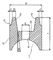
図1において、溝付き異形線材1は、その幅Bが1.50〜1.55mm、厚さTが1.50〜2.00mmであり、長手方向に連続するレール部2、2間のウェブ部3に、幅Eが0.30〜0.40mmである油孔4を直列状に形成して成る。また、レール部2の摺動面の幅Dは0.13〜0.19mmにし、レール部の内側傾斜角度θは3〜7°にして成る。
In FIG. 1, the grooved
この場合、レール部2の外側傾斜面の下端と側面5の上端とを直接接続する構成にしてもよいが、段部6で接続した構成にすると、間隔Cを0.08mm以上により一層容易にすることができる。
In this case, the lower end of the outer inclined surface of the
上記構成における数値限定の理由は次のとおりである。
レール部2の摺動面の幅Dを0.13〜0.19mmの範囲にし、レール部の内側傾斜角度θを3〜7°の範囲にしたのは、溝付異形線材1の幅B内において、油掻き落とし作用上必要なレール部の幅と油孔の幅Eを確保しながら、レール部の外側隅部と両側面の延長した基準線との間隔Cを0.08mm以上取るためである。
The reason for the numerical limitation in the above configuration is as follows.
The reason why the width D of the sliding surface of the
次に、この形態に係る溝付異形線材1は、例えば次の方法により製造することができる。
Next, the irregular
マルテンサイト系ステンレス鋼線を伸線加工して所要線径に減径し、この線材を焼きなまし処理により軟化させた後、溝を有するロールによって上下、左右方向の圧延加工を複数回にわたって行い所要の形状に形成する。次に、打ち抜き加工によって、線材長手方向のウェブ部に油孔を設けたのち、オイルリング用異形線材として必要な強度、バネ性、真直性を得るために焼き入れ焼き戻し処理を施す。 A martensitic stainless steel wire is drawn and reduced to the required wire diameter. After the wire is softened by annealing treatment, rolling is performed multiple times in the vertical and horizontal directions with a roll having grooves. Form into shape. Next, after providing oil holes in the web portion in the longitudinal direction of the wire by punching, a quenching and tempering treatment is performed in order to obtain strength, springiness, and straightness necessary for the deformed wire for the oil ring.
上記のようにして得られたオイルリング用異形線材をリング加工した後、窒化処理を施してオイルリングとなし、これをシリンダに装着して油掻き性について試験を行い評価を行った。 The deformed wire rod for oil ring obtained as described above was subjected to ring processing, and then subjected to nitriding treatment to form an oil ring, which was mounted on a cylinder, tested for oil scraping, and evaluated.
その結果、従来の2ピース構造のオイルリングと同等以上の油掻き性を有することが確認できた。 As a result, it was confirmed that the oil ring had the same or better oil-scraping property than the conventional two-piece structure oil ring.
1 溝付異形線材
2 レール部
3 ウェブ部
4 油孔
5 側面
6 段部
B 溝付異形線材の幅
C 間隔
D レール部摺動面の幅
E 油孔の幅
T 溝付異形線材の厚さ
θ 内側傾斜角度
DESCRIPTION OF
Claims (5)
Priority Applications (1)
| Application Number | Priority Date | Filing Date | Title |
|---|---|---|---|
| JP2004103148A JP2005291003A (en) | 2004-03-31 | 2004-03-31 | Odd-form wire rod with groove for two-piece type oil ring |
Applications Claiming Priority (1)
| Application Number | Priority Date | Filing Date | Title |
|---|---|---|---|
| JP2004103148A JP2005291003A (en) | 2004-03-31 | 2004-03-31 | Odd-form wire rod with groove for two-piece type oil ring |
Publications (1)
| Publication Number | Publication Date |
|---|---|
| JP2005291003A true JP2005291003A (en) | 2005-10-20 |
Family
ID=35324234
Family Applications (1)
| Application Number | Title | Priority Date | Filing Date |
|---|---|---|---|
| JP2004103148A Pending JP2005291003A (en) | 2004-03-31 | 2004-03-31 | Odd-form wire rod with groove for two-piece type oil ring |
Country Status (1)
| Country | Link |
|---|---|
| JP (1) | JP2005291003A (en) |
Cited By (7)
| Publication number | Priority date | Publication date | Assignee | Title |
|---|---|---|---|---|
| JP2008291991A (en) * | 2007-04-27 | 2008-12-04 | Nippon Piston Ring Co Ltd | Oil ring for internal combustion engine |
| JP2010530045A (en) * | 2007-06-13 | 2010-09-02 | フェデラル−モーグル ブルシャイト ゲゼルシャフト ミット ベシュレンクテル ハフツング | Oil scraping ring |
| WO2010124353A1 (en) * | 2009-04-30 | 2010-11-04 | Mahle Metal Leve S/A | Oil control ring with ferrous body less than 2.0 millimeters high for internal combustion engines |
| WO2011151069A1 (en) * | 2010-06-04 | 2011-12-08 | Mahle International Gmbh | Oil control ring of ferrous body for internal combustion engines |
| JP2012215237A (en) * | 2011-03-31 | 2012-11-08 | Nippon Piston Ring Co Ltd | Combination of piston ring for diesel engine |
| JP2012215238A (en) * | 2011-03-31 | 2012-11-08 | Nippon Piston Ring Co Ltd | Combination of piston ring for gasoline engine |
| CN105934613A (en) * | 2014-03-04 | 2016-09-07 | 辉门布尔沙伊德有限公司 | Oil scraper piston ring and method for producing an oil scraper piston ring |
-
2004
- 2004-03-31 JP JP2004103148A patent/JP2005291003A/en active Pending
Cited By (10)
| Publication number | Priority date | Publication date | Assignee | Title |
|---|---|---|---|---|
| JP2008291991A (en) * | 2007-04-27 | 2008-12-04 | Nippon Piston Ring Co Ltd | Oil ring for internal combustion engine |
| JP2010530045A (en) * | 2007-06-13 | 2010-09-02 | フェデラル−モーグル ブルシャイト ゲゼルシャフト ミット ベシュレンクテル ハフツング | Oil scraping ring |
| WO2010124353A1 (en) * | 2009-04-30 | 2010-11-04 | Mahle Metal Leve S/A | Oil control ring with ferrous body less than 2.0 millimeters high for internal combustion engines |
| US9163725B2 (en) | 2009-04-30 | 2015-10-20 | Mahle Metal Leve S/A | Oil control ring with ferrous body less than 2.0 millimeters high for internal combustion engines |
| WO2011151069A1 (en) * | 2010-06-04 | 2011-12-08 | Mahle International Gmbh | Oil control ring of ferrous body for internal combustion engines |
| JP2012215237A (en) * | 2011-03-31 | 2012-11-08 | Nippon Piston Ring Co Ltd | Combination of piston ring for diesel engine |
| JP2012215238A (en) * | 2011-03-31 | 2012-11-08 | Nippon Piston Ring Co Ltd | Combination of piston ring for gasoline engine |
| CN105934613A (en) * | 2014-03-04 | 2016-09-07 | 辉门布尔沙伊德有限公司 | Oil scraper piston ring and method for producing an oil scraper piston ring |
| JP2017508925A (en) * | 2014-03-04 | 2017-03-30 | フェデラル−モーグル ブルシェイド ゲーエムベーハーFederal−Mogul Burscheid Gmbh | Oiled piston ring and method of manufacturing oiled piston ring |
| CN105934613B (en) * | 2014-03-04 | 2018-11-09 | 辉门布尔沙伊德有限公司 | Oil scraper piston ring and method for manufacturing oil scraper piston ring |
Similar Documents
| Publication | Publication Date | Title |
|---|---|---|
| EP1377766B1 (en) | Side rail and combined oil control ring incorporated with the side rails for reduction of oil consumption | |
| US4522412A (en) | Oil ring with coil expander | |
| KR20130116870A (en) | Method for producing a piston ring | |
| JP2009156392A (en) | Cage for roller bearing, needle roller bearing, and method for manufacturing cage for roller bearing | |
| JP2006070827A (en) | High-pressure fuel injection pipe and molding method therefor | |
| JP2005291003A (en) | Odd-form wire rod with groove for two-piece type oil ring | |
| JP2004257563A (en) | Deep rolling method for radius part or fillet part | |
| JP2009156393A (en) | Retainer for roller bearing, and needle roller bearing | |
| JP5346465B2 (en) | Roller bearing cage and needle roller bearing | |
| JP2006017287A (en) | Piston ring for internal combustion engine | |
| KR960016989A (en) | Flat steel wire for side rail of oil ring of internal combustion engine and its manufacturing method | |
| JP5651353B2 (en) | Shaving mold | |
| JP3943115B2 (en) | Forming material for forging, forged product, and forming method for forming forging | |
| JP2006194320A (en) | Roller bearing manufacturing method and roller bearing | |
| JP5049143B2 (en) | Connecting rod large end support structure and motorcycle engine | |
| JP4143857B2 (en) | Die forging method and forging die | |
| JP4199596B2 (en) | Deformed wire rod with groove for pressure ring | |
| JPH10252890A (en) | Oil ring | |
| JP2000352423A (en) | Roller with cage | |
| JP5246742B2 (en) | Roller bearing cage and needle roller bearing | |
| JP2009156389A (en) | Cage for roller bearing and needle roller bearing | |
| JP2007092843A (en) | Wire for oil ring | |
| JP2007170455A (en) | Combined oil ring | |
| JP5346471B2 (en) | Needle roller bearing | |
| JPH0424122Y2 (en) |