JP2005290970A - Clearance closing implement - Google Patents
Clearance closing implement Download PDFInfo
- Publication number
- JP2005290970A JP2005290970A JP2005056309A JP2005056309A JP2005290970A JP 2005290970 A JP2005290970 A JP 2005290970A JP 2005056309 A JP2005056309 A JP 2005056309A JP 2005056309 A JP2005056309 A JP 2005056309A JP 2005290970 A JP2005290970 A JP 2005290970A
- Authority
- JP
- Japan
- Prior art keywords
- groove
- door
- operating body
- shutter piece
- control mechanism
- Prior art date
- Legal status (The legal status is an assumption and is not a legal conclusion. Google has not performed a legal analysis and makes no representation as to the accuracy of the status listed.)
- Pending
Links
- 239000000725 suspension Substances 0.000 claims description 16
- 230000008961 swelling Effects 0.000 abstract 2
- 238000009423 ventilation Methods 0.000 description 4
- 238000000034 method Methods 0.000 description 3
- 229920003002 synthetic resin Polymers 0.000 description 3
- 239000000057 synthetic resin Substances 0.000 description 3
- 229910052782 aluminium Inorganic materials 0.000 description 2
- XAGFODPZIPBFFR-UHFFFAOYSA-N aluminium Chemical compound [Al] XAGFODPZIPBFFR-UHFFFAOYSA-N 0.000 description 2
- 238000005399 mechanical ventilation Methods 0.000 description 2
- 229910052751 metal Inorganic materials 0.000 description 2
- 239000002184 metal Substances 0.000 description 2
- 239000000853 adhesive Substances 0.000 description 1
- 230000001070 adhesive effect Effects 0.000 description 1
- 230000005494 condensation Effects 0.000 description 1
- 238000009833 condensation Methods 0.000 description 1
- 229920003051 synthetic elastomer Polymers 0.000 description 1
- 239000005061 synthetic rubber Substances 0.000 description 1
Images

Landscapes
- Specific Sealing Or Ventilating Devices For Doors And Windows (AREA)
Abstract
Description
本発明はすき間閉止具に関する。さらに詳しくは、扉や吊り戸と床面とのあいだのすき間を塞いで、居室内へのすきま風の侵入を防ぐことができるすき間閉止具に関する。 The present invention relates to a gap closing device. More specifically, the present invention relates to a gap closing device that closes a gap between a door or a suspension door and a floor surface and can prevent a gap air from entering a living room.
マンションや一戸建てなどの住宅、および事務所などにおける居室では、室内の汚れた空気を外気と交換してきれいにしたり、または季節によっては室内を乾燥させて結露などを防ぐために換気が行なわれている。 In living rooms such as apartments and detached houses, and offices, the dirty air in the room is exchanged with the outside air to clean it, or in some seasons the room is dried to prevent condensation. .
室内を換気する方法としては、定期的に窓などの開口部を開放する自然換気方式と、換気扇や空調機などの機械設備を用いて空気を入れ換える機械換気方式とがある。 As a method for ventilating the room, there are a natural ventilation method in which openings such as windows are periodically opened and a mechanical ventilation method in which air is exchanged by using mechanical equipment such as a ventilation fan or an air conditioner.
ところで、機械換気方式の場合、単に排気機能だけを備えた設備(たとえば、換気扇)を用いると、室内への空気の流入を確保しないと適切な換気を行なうことができない。 By the way, in the case of the mechanical ventilation system, if an equipment having only an exhaust function (for example, a ventilation fan) is used, appropriate ventilation cannot be performed unless the inflow of air into the room is ensured.
そこで、最近では、室内環境に対する意識の向上と相俟って、扉や吊り戸の下端面と床との隙間を大きく設定することが行なわれている。具体的には、従来では3〜5mm程度であった隙間を1cm程度まで広げる設計が行なわれている。 Therefore, recently, in conjunction with the improvement of the consciousness about the indoor environment, a large gap is set between the lower end surface of the door or the hanging door and the floor. Specifically, a design that widens the gap of about 3 to 5 mm, which was conventionally about 3 to 5 mm, is performed.
しかしながら、空気の循環という点からは、前記すき間を大きく設定するのが好ましいが、とくに冬場においては、前記すき間から流れ込むすきま風によって、居住者が不快を感じるという問題がある。とくに扉や吊り戸の近くにソファをおいた場合、足元にすきま風があたるためゆっくりとくつろぐことができなかった。 However, from the viewpoint of air circulation, it is preferable to set the gap large. However, particularly in winter, there is a problem that the resident feels uncomfortable due to the gap air flowing from the gap. In particular, when a sofa was placed near the door or suspension door, it was impossible to relax slowly because of a draft at the foot.
本発明はかかる問題を解消するためになされたものであり、扉や吊り戸の下端面と床とのすき間を塞いで、居室へのすきま風の流入を防ぐことができるすき間閉止具を提供することを目的とする。 The present invention has been made to solve such a problem, and provides a gap closing device capable of closing a gap between a lower end surface of a door or a hanging door and a floor and preventing an inflow of a draft into a living room. With the goal.
本発明のすき間閉止具は、扉の下端に取り付けられ、当該扉の下端面と床とのあいだのすき間を塞ぐのに用いられるすき間閉止具であって、
扉の幅とほぼ同じ長さの長尺部材からなり、該長尺部材には、その長手方向に沿って溝が形成されており、該溝の開口縁には膨出部が形成されている閉止具本体と、
扉の幅とほぼ同じ長さの帯板状部材からなり、その長辺の一辺に前記膨出部と係合する係合フックを有するシャッター片と、
前記閉止具本体の溝内に摺動自在に挿入される操作体と、
前記閉止具本体の構内に収容され、前記操作体を当該溝から突出する方向へ付勢する付勢手段と、
前記シャッター片の、前記係合フックを中心とする回動運動を制御する回動制御機構と、
前記操作体を前記溝から所定の距離だけ突出した状態に保つ突出位置制御機構と
を備えていることを特徴としている。
The gap closing device of the present invention is a gap closing device which is attached to the lower end of the door and used to close the gap between the lower end surface of the door and the floor,
It consists of a long member having the same length as the width of the door. The long member has a groove along its longitudinal direction, and a bulging portion is formed at the opening edge of the groove. A closure body;
A shutter piece having an engagement hook that engages with the bulging portion on one side of a long plate made of a strip-like member having a length substantially the same as the width of the door;
An operating body slidably inserted into the groove of the closure body;
A biasing means that is accommodated in the premises of the closure main body and biases the operating body in a direction protruding from the groove;
A rotation control mechanism for controlling a rotation motion of the shutter piece around the engagement hook;
And a protruding position control mechanism that keeps the operating body protruding from the groove by a predetermined distance.
また、本発明のすき間閉止具は、吊り戸の下端に取り付けられ、当該吊り戸の下端面と床とのあいだのすき間を塞ぐのに用いられるすき間閉止具であって、
吊り戸の幅とほぼ同じ長さの長尺部材からなり、該長尺部材には、その長手方向に沿って溝が形成されており、該溝の開口縁には膨出部が形成されている閉止具本体と、
吊り戸の幅とほぼ同じ長さの帯板状部材からなり、その長辺の一辺に前記膨出部と係合する係合フックを有するシャッター片と、
前記閉止具本体の溝内に摺動自在に挿入される操作体と、
前記閉止具本体の構内に収容され、前記操作体を当該溝から突出する方向へ付勢する付勢手段と、
前記シャッター片の、前記係合フックを中心とする回動運動を制御する回動制御機構と、
前記操作体を前記溝から所定の距離だけ突出した状態に保つ突出位置制御機構と
を備えていることを特徴としている。
Further, the gap closing device of the present invention is a gap closing device that is attached to the lower end of the suspension door and used to close the gap between the lower end surface of the suspension door and the floor,
It consists of a long member of the same length as the width of the suspension door, and the long member has a groove formed along its longitudinal direction, and a bulging portion is formed at the opening edge of the groove. A closure body,
A shutter piece comprising a band plate-like member having a length substantially the same as the width of the suspension door, and having an engagement hook that engages with the bulging portion on one side of the long side;
An operating body slidably inserted into the groove of the closure body;
A biasing means that is accommodated in the premises of the closure main body and biases the operating body in a direction protruding from the groove;
A rotation control mechanism for controlling a rotation motion of the shutter piece around the engagement hook;
And a protruding position control mechanism that keeps the operating body protruding from the groove by a predetermined distance.
前記操作体が板状部材で作製されており、前記回動制御機構が、前記シャッター片の係合フックの外表面に形成された突起と、前記操作体の片面に形成された凹所とからなり、該凹所には前記操作体の表面から当該凹所の底面に至る斜面が形成されており、さらに前記操作体が溝から突出した状態において当該操作体の表面が前記突起と当接し、前記操作体が溝内に押し込まれる状態において前記突起が前記斜面を経由して凹所内に収容されるように、前記突起および凹所が位置決めされてなるのが好ましい。 The operating body is made of a plate-shaped member, and the rotation control mechanism includes a protrusion formed on the outer surface of the engagement hook of the shutter piece and a recess formed on one side of the operating body. The slope is formed from the surface of the operating body to the bottom surface of the recess in the recess, and the surface of the operating body abuts the protrusion in a state where the operating body protrudes from the groove, It is preferable that the protrusion and the recess are positioned so that the protrusion is accommodated in the recess via the slope in a state where the operation body is pushed into the groove.
前記突出位置制御機構が、前記操作体の長手方向に沿って形成されたスリットと、該スリットに挿通されるピンとからなるのが好ましい。 It is preferable that the protruding position control mechanism includes a slit formed along the longitudinal direction of the operation body and a pin inserted through the slit.
また、前記操作体の長さが、前記閉止具本体の長さのほぼ半分であることが好ましい。 Moreover, it is preferable that the length of the operation body is substantially half of the length of the closure main body.
本発明のすき間閉止具によれば、扉や吊り戸を閉めた状態において、シャッター片の一辺が床面に接するように当該シャッター片が回動するので、扉や吊り戸と床とのすき間を塞ぐことができ、それにより居室へのすきま風の流入を防ぐことができる。 According to the gap closing device of the present invention, when the door or the suspension door is closed, the shutter piece rotates so that one side of the shutter piece contacts the floor surface. It can be blocked, thereby preventing the inflow of draft air into the room.
以下、添付図面に基づいて本発明のすき間閉止具を詳細に説明する。 Hereinafter, the gap closing device of the present invention will be described in detail with reference to the accompanying drawings.
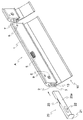
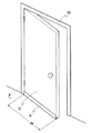
図1は、本発明のすき間閉止具の一実施の形態の一部破断説明図であり、図1に示されるすき間閉止具Aは、長尺部材からなる閉止具本体1と、帯板状部材からなるシャッター片10と、操作体20と、付勢手段5と、前記シャッター片10の回動運動を制御する回動制御機構と、前記操作体20の突出位置を制御する突出位置制御機構とを備えている。前記すき間閉止具Aは、図5〜6に示されるように、扉Dの下端に取り付けられ、当該扉Dと床Fとのあいだのすき間を塞ぐのに用いられたり、または図示していないが、吊り戸の下端に取り付けられ、当該吊り戸と床とのあいだのすき間を塞ぐのに用いられる。
FIG. 1 is a partially broken explanatory view of an embodiment of a gap closing device of the present invention. A gap closing device A shown in FIG. 1 includes a
前記閉止具本体1を構成する長尺部材は、すき間閉止具Aが取り付けられる扉または吊り戸の幅とほぼ同じ長さを有しており、合成樹脂や、アルミニウムなどの金属などで作製することができる。閉止具本体1には、その長手方向に沿って溝2が形成されており、該溝2の中には、付勢手段5および操作体20が収容される。また、溝2の開口縁には、断面がほぼ円形の膨出部3が形成されている。本実施の形態では、前記膨出部3は、溝の開口縁から溝の内部に向かって突出するように形成されており、この膨出部3に後述するシャッター片10の係合フックが係合する。
The long member constituting the closure
シャッター片10も、前記閉止具本体1と同様に扉または吊り戸の幅とほぼ同じ長さを有しており、合成樹脂やゴムなどで作製することができる。図1〜2に示されるように、シャッター片10の長辺のうちの一辺には前記膨出部3と係合する係合フック13が形成されている。この係合フック13は、前記膨出部3の外形(ほぼ円形)に対応して、その断面が、リングの一部分を呈する形状であり、係合フック13の内側の面が膨出部3と接触するように、係合フック13と膨出部3の係合が行なわれる。本実施の形態のシャッター片10は、前記係合フック13が形成された部分を含む厚肉部11と、床面と接触する側の薄肉部12とから構成されている。薄肉部12の縁には、断面がほぼ円形の膨出部12aが形成されている。係合フック13の部分は、シャッター片10の複数回(通常、10〜20万回程度)の回動運動に耐えて前記係合フック13のフック部分の形状が保持できるように厚肉にされており、一方、先端側は、シャッター片10全体の軽量化のため、シャッター片10が上昇した位置において、当該シャッター片10が垂れ下がらない程度の形状保持性が得られる程度に薄肉にされている。シャッター片10が重くなりすぎると、後述するように、付勢手段5の付勢力のみで床面とほぼ平行な状態までシャッター片10を回動させるのが難しくなるとともに、シャッター片10が下降して床面に接触したときに大きな音が発生する可能性がある。
The
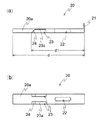
前記操作体20は、前記閉止具本体1の溝2内に摺動自在に挿入され、本実施の形態においては、図1および3に示されるように板状部材で作製されている。操作体20の長さd(図3(a)参照)の長さは特定の長さに限定されないが、閉止具本体1の長さをWとすると(図6参照)、d≧(W/2)の関係を満たすが、または凹所23が当接片21から距離d1だけ離間した位置に形成されているしたとき(図3(a)参照)、凹所23の位置d1が閉止具本体1のほぼ中央(すなわちd1≒(W/2))になるような寸法にすると、シャッター片10のほぼ中心で支持することができるため、シャッター片10の荷重を左右均等に分散することができるという利点がある。このため、シャッター片10が重くなりすぎても、付勢手段5の付勢力のみで床面とほぼ平行な状態までシャッター片10を回動させることができる。この操作体20は、合成樹脂やアルミニウムなどの金属で作製することができる。操作体20の一方の端部(閉止具本体1の溝2に挿入される側と反対側の端部)には当接片21が形成されている。この当接片21は、操作体20の本体部分20aと一体に形成してもよいし、該本体部分20aとは別体とし、本体部分20aに固着するようにしてもよい。この当接片21は、扉が閉められたとき、または吊り戸が閉められたときに、扉の枠部材30(図6参照)または柱(図示せず)などに当接して、付勢手段5の付勢力に抗して前記操作体20を溝2内に押し込む役割を果たしている。
The
操作体20には、長手方向に沿ってスリット22が形成されており、このスリット22と、閉止具本体1に穿設された孔6から前記スリット22に挿通されるピン25とにより、前記操作体20を閉止具本体1の溝から所定の距離だけ突出した状態に保つ突出位置制御機構が構成される。
A
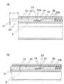
すなわち、操作体20は、付勢手段5によって常時溝2から飛び出る方向に付勢されているが、図4の(a)に示されるように、ピン25がスリット22の最も奥側(溝2の内部側)の壁に当接するため、操作体20は、図4の(a)において所定の距離Lだけ突出した状態に保たれる。この距離Lは、スリットとピンの位置を変えることにより、調節することができる。
In other words, the operating
なお、本実施の形態においては、スリットとピンとにより突出位置制御機構を構成したが、本発明はこれに限定されるものではなく、たとえば、当接片から所定の距離において操作体20につば部を形成し、溝2(つば部が挿入しうる断面形状の溝)内に操作体20を挿入したのちに、溝2の入口部分に前記つば部の抜け止めを設けることもできる。この場合、前記つば部と抜け止めが突出位置制御機構を構成する。
In the present embodiment, the protrusion position control mechanism is configured by the slit and the pin. However, the present invention is not limited to this, and for example, the flange portion of the operating
前記付勢手段5は閉止具本体1の溝2内に収容され、前記操作体20を溝2から突出する方向へ付勢しており、本実施の形態では、この付勢手段5としてコイルばねが用いられているが、本発明は、これに限定されるものではなく、他にオイルばねなどを用いることもできる。付勢手段5の一端(溝の奥側の端部)は、閉止具本体1に穿設された孔7内に圧入されたストッパ8に当接している。
The urging means 5 is accommodated in the
本発明のすき間閉止具は、扉が開いている状態では、シャッター片10が上昇位置にあり、扉を閉めた状態では、シャッター片10が下降位置にあることを特徴とするものであるが、かかるシャッター片10の、係合フック13を中心とする回動運動を制御する回動制御機構として、本実施の形態では、シャッター片10に設けられた突起14と操作体20に形成された凹所23が採用されている。
The gap closing device of the present invention is characterized in that the
すなわち、シャッター片10の係合フック13の外表面には突起14が形成されている(図2参照)。また、操作体20の片面には、凹所23が上下2段に形成されている。さらに、この凹所23には、操作体20の表面20bから当該凹所23の底面23aに至る斜面24が形成されている。この斜面24は、凹所23の奥側(溝2の内部側)に形成されている。
That is, the
つぎに、突起14および凹所23からなる回動制御機構の作用について図4を参照しつつ説明する。
Next, the operation of the rotation control mechanism including the
図4の(a)に示されるように、扉が開いた状態では、操作体20の当接片21は扉の枠部材30に当接していないため、操作体20は付勢手段5の付勢力によって所定の距離Lだけ溝2から突出している。この距離Lは、前述したように、操作体20のスリット22と、該スリット22に挿通されたピン25により制御されている。
As shown in FIG. 4A, when the door is open, the
この状態では、シャッター片10の突起14が操作体20の表面20bと、閉止具本体1の溝の内面2aとにはさまれており、シャッター片10が自重により膨出部3を中心にして回動しようとしても、操作体20の表面20bに邪魔されて回動することができない。
In this state, the
一方、扉を閉じていくと、操作体20の当接片21(図6においては、扉のヒンジ側にあるため図示されていない)が扉の枠部材30に接触し、付勢手段5の付勢力に抗して、操作体20は溝の奥の方へ押し込まれていき、やがて扉が完全に閉まると、図4の(b)で示される状態になる。
On the other hand, when the door is closed, the
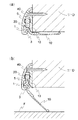
操作体20が溝2内に押し込まれるのに併行して、シャッター片10の自重による当該シャッター片10の回動によって、突起14が操作体20の表面20bおよび斜面24を経由して凹所23の底面23aに当接するまで移動をする。突起14が底面23aに当接するまで回動すると、シャッター片10の先端は床面に接触する。
In parallel with the
図5の(a)は図4の(a)に示される状態に対応しており、また図5の(b)は図4の(b)に示される状態に対応している。 5A corresponds to the state shown in FIG. 4A, and FIG. 5B corresponds to the state shown in FIG. 4B.
本発明のすき間閉止具は、閉止具本体1に穿設された孔9(図1参照)を利用して、図6に示されるように扉の下端にネジ、ビスもしくはくぎ、または接着剤などにより取り付けることができる。図1〜6に示される実施の形態では、孔9にネジ40を螺入することにより、すき間閉止具を扉に取り付けている。
The gap closing device of the present invention uses a hole 9 (see FIG. 1) drilled in the
なお、本実施の形態のすき間閉止具Aは左右対象となるように作製されており、扉の開き勝手(右開きまたは左開き)に対応して、扉に取り付けることができる。そして、これに対応して、前記操作体20には上下2段の凹所が形成されている。図1に示される状態では、下側の凹所がシャッター片の突起と係合するが、反対側から操作体を挿入する場合は、図1に示される状態において上側の凹所(実際に反対側の溝内に挿入するときには、操作体が上下逆になるので、下側にくる)がシャッター片の突起と係合することになる。
In addition, the gap closing tool A of this Embodiment is produced so that it may become right-and-left object, and can be attached to a door corresponding to the door opening hand (right opening or left opening). Corresponding to this, the operating
また、予め扉の幅に合わせた長さのすき間閉止具を作製しておくこともできるが、一定の長さのすき間閉止具を作製しておいて、現場で扉の幅に合わせてすき間閉止具を切断するようにしてもよい。 In addition, it is possible to prepare a gap closing tool with a length that matches the width of the door in advance, but it is possible to create a gap closing tool with a certain length and close the gap according to the width of the door at the site. You may make it cut | disconnect a tool.
A すき間閉止具
D 扉
F 床
1 閉止具本体
2 溝
5 コイルばね
8 ストッパ
10 シャッター片
13 係合フック
14 突起
20 操作体
21 当接片
23 凹所
24 斜面
A Clearance closing tool D
Claims (5)
扉の幅とほぼ同じ長さの長尺部材からなり、該長尺部材には、その長手方向に沿って溝が形成されており、該溝の開口縁には膨出部が形成されている閉止具本体と、
扉の幅とほぼ同じ長さの帯板状部材からなり、その長辺の一辺に前記膨出部と係合する係合フックを有するシャッター片と、
前記閉止具本体の溝内に摺動自在に挿入される操作体と、
前記閉止具本体の構内に収容され、前記操作体を当該溝から突出する方向へ付勢する付勢手段と、
前記シャッター片の、前記係合フックを中心とする回動運動を制御する回動制御機構と、
前記操作体を前記溝から所定の距離だけ突出した状態に保つ突出位置制御機構と
を備えていることを特徴とするすき間閉止具。 A gap closing device that is attached to the lower end of the door and used to close the gap between the lower end surface of the door and the floor,
It consists of a long member having a length substantially the same as the width of the door, and a groove is formed along the longitudinal direction of the long member, and a bulging portion is formed at the opening edge of the groove. A closure body;
A shutter piece having an engagement hook that engages with the bulging portion on one side of a long plate made of a strip-like member having a length substantially the same as the width of the door;
An operating body slidably inserted into the groove of the closure body;
A biasing means that is accommodated in the premises of the closure main body and biases the operating body in a direction protruding from the groove;
A rotation control mechanism for controlling a rotation motion of the shutter piece around the engagement hook;
A gap closing tool comprising: a protruding position control mechanism that keeps the operating body protruding from the groove by a predetermined distance.
吊り戸の幅とほぼ同じ長さの長尺部材からなり、該長尺部材には、その長手方向に沿って溝が形成されており、該溝の開口縁には膨出部が形成されている閉止具本体と、
吊り戸の幅とほぼ同じ長さの帯板状部材からなり、その長辺の一辺に前記膨出部と係合する係合フックを有するシャッター片と、
前記閉止具本体の溝内に摺動自在に挿入される操作体と、
前記閉止具本体の構内に収容され、前記操作体を当該溝から突出する方向へ付勢する付勢手段と、
前記シャッター片の、前記係合フックを中心とする回動運動を制御する回動制御機構と、
前記操作体を前記溝から所定の距離だけ突出した状態に保つ突出位置制御機構と
を備えていることを特徴とするすき間閉止具。 A gap closing device that is attached to the lower end of the suspension door and is used to close the gap between the lower end surface of the suspension door and the floor,
It consists of a long member of the same length as the width of the suspension door, and the long member has a groove formed along its longitudinal direction, and a bulging portion is formed at the opening edge of the groove. A closure body,
A shutter piece comprising a band plate-like member having a length substantially the same as the width of the suspension door, and having an engagement hook that engages with the bulging portion on one side of the long side;
An operating body slidably inserted into the groove of the closure body;
A biasing means that is accommodated in the premises of the closure main body and biases the operating body in a direction protruding from the groove;
A rotation control mechanism for controlling a rotation motion of the shutter piece around the engagement hook;
A gap closing tool comprising: a protruding position control mechanism that keeps the operating body protruding from the groove by a predetermined distance.
Priority Applications (1)
| Application Number | Priority Date | Filing Date | Title |
|---|---|---|---|
| JP2005056309A JP2005290970A (en) | 2004-03-09 | 2005-03-01 | Clearance closing implement |
Applications Claiming Priority (2)
| Application Number | Priority Date | Filing Date | Title |
|---|---|---|---|
| JP2004066031 | 2004-03-09 | ||
| JP2005056309A JP2005290970A (en) | 2004-03-09 | 2005-03-01 | Clearance closing implement |
Publications (1)
| Publication Number | Publication Date |
|---|---|
| JP2005290970A true JP2005290970A (en) | 2005-10-20 |
Family
ID=35324209
Family Applications (1)
| Application Number | Title | Priority Date | Filing Date |
|---|---|---|---|
| JP2005056309A Pending JP2005290970A (en) | 2004-03-09 | 2005-03-01 | Clearance closing implement |
Country Status (1)
| Country | Link |
|---|---|
| JP (1) | JP2005290970A (en) |
Cited By (1)
| Publication number | Priority date | Publication date | Assignee | Title |
|---|---|---|---|---|
| JP2022127154A (en) * | 2021-02-19 | 2022-08-31 | 三和シヤッター工業株式会社 | Sealing structure with movable sealing member |
-
2005
- 2005-03-01 JP JP2005056309A patent/JP2005290970A/en active Pending
Cited By (2)
| Publication number | Priority date | Publication date | Assignee | Title |
|---|---|---|---|---|
| JP2022127154A (en) * | 2021-02-19 | 2022-08-31 | 三和シヤッター工業株式会社 | Sealing structure with movable sealing member |
| JP7650679B2 (en) | 2021-02-19 | 2025-03-25 | 三和シヤッター工業株式会社 | Sealed structure with movable seal |
Similar Documents
| Publication | Publication Date | Title |
|---|---|---|
| KR200458368Y1 (en) | Window frame fixing ventilator | |
| WO2009020170A1 (en) | Indoor unit for air conditioner | |
| JP6751484B2 (en) | Sliding door fittings that can be automatically ventilated by automatic opening and closing | |
| KR102039834B1 (en) | Non-perforate type Ventilation equipment for window | |
| JP6479066B2 (en) | Joinery and ventilation valve operation parts | |
| KR20170046117A (en) | Ventilation Apparatus of Hinge Door | |
| KR100773155B1 (en) | Window system with double window | |
| KR101414149B1 (en) | Self-closing apparatus for window | |
| KR20110105505A (en) | Opening and closing controller of window ventilating system | |
| KR20140091427A (en) | Locking structure for an opening and closing apparatus of the smoke ventilating window | |
| JP6184152B2 (en) | Joinery and ventilation valve operation parts | |
| JP2005127120A (en) | Natural ventilator | |
| JP3118504B2 (en) | Ventilation equipment | |
| JPH11281114A (en) | Air supply adjustment device | |
| JP5308071B2 (en) | Opening and closing of bathroom door | |
| JP2018159209A (en) | Ventilator and joinery | |
| KR200481687Y1 (en) | Anti-condensation device of shutter switchgear for ventilation windows | |
| DE50201254D1 (en) | Slat for shading or light control on buildings | |
| KR101503744B1 (en) | Opening And Shutting Apparatus Of Ventilation Window | |
| JP2912183B2 (en) | Door frame with ventilation and lighting functions | |
| JP2002168508A (en) | Ventilation equipment | |
| JP3865645B2 (en) | Supply / exhaust vent | |
| KR20090010386U (en) | Ventilation vents for building exterior walls | |
| JPH08152163A (en) | Automatically opening/closing type air supply louver | |
| KR200492076Y1 (en) | Auto self-closing apparatus for window |
Legal Events
| Date | Code | Title | Description |
|---|---|---|---|
| A621 | Written request for application examination |
Free format text: JAPANESE INTERMEDIATE CODE: A621 Effective date: 20060619 |
|
| A977 | Report on retrieval |
Free format text: JAPANESE INTERMEDIATE CODE: A971007 Effective date: 20080430 |
|
| A131 | Notification of reasons for refusal |
Free format text: JAPANESE INTERMEDIATE CODE: A131 Effective date: 20080507 |
|
| A02 | Decision of refusal |
Free format text: JAPANESE INTERMEDIATE CODE: A02 Effective date: 20080909 |