JP2005290969A - Protective cover for water line gate valve - Google Patents
Protective cover for water line gate valve Download PDFInfo
- Publication number
- JP2005290969A JP2005290969A JP2004335238A JP2004335238A JP2005290969A JP 2005290969 A JP2005290969 A JP 2005290969A JP 2004335238 A JP2004335238 A JP 2004335238A JP 2004335238 A JP2004335238 A JP 2004335238A JP 2005290969 A JP2005290969 A JP 2005290969A
- Authority
- JP
- Japan
- Prior art keywords
- gate valve
- water gate
- protective cover
- synthetic resin
- peripheral surface
- Prior art date
- Legal status (The legal status is an assumption and is not a legal conclusion. Google has not performed a legal analysis and makes no representation as to the accuracy of the status listed.)
- Granted
Links
Images


Landscapes
- Valve Housings (AREA)
Abstract
Description
本発明は、道路下に埋設される水道管の水道仕切弁の保護カバーの改良に関する。 The present invention relates to an improvement in a protective cover for a water gate valve of a water pipe buried under a road.
本発明者は、特開2002−138523号公報(特許文献1)に示すように、コンクリートボックスを浅埋形のものに変えてコンクリートボックス底版と浅埋された水道管との距離を大きくとるようにして道路上の車両等の荷重の影響を少なくし、又、水道管のジョイント部分等からの水洩れの発生を防止すると共に、コンクリートボックスに挿入された合成樹脂製の保護カバーを設けて、水道仕切弁のフランジより上方を雨水や土砂から保護できると共に、地震等によるコンクリートボックスのズレが発生しないことに成功したが、水道仕切弁本体は、水道本管の口径50ミリメートル、75ミリメートル、100ミリメートル、150ミリメートル、200ミリメートル、250ミリメートル等に対応して形状が大きくなり、また、製品メーカーにより形状の相違があり、一定の大きさの合成樹脂製の保護カバーでは対応できない問題が生じた。そこで発明者は、多用される一定範囲の水道仕切弁に適用できる一定大きさの合成樹脂製保護カバーを開発することに成功し、また、夜間点検を容易にできる保護カバーの開発にも成功した。この改良発明に関し、円筒部分と下部が末広がり部分の保護カバーで水道仕切弁を嵌入していることを特徴とする水道仕切弁の保護カバーについての特許出願を行っている(特願2004−63760)。 As shown in Japanese Patent Application Laid-Open No. 2002-138523 (Patent Document 1), the present inventor changes the concrete box to a shallow buried type so as to increase the distance between the concrete box bottom plate and the shallowly buried water pipe. In order to reduce the influence of the load of vehicles on the road, and prevent the occurrence of water leakage from the joints of the water pipe, etc., and provide a protective cover made of synthetic resin inserted in the concrete box, Although the upper part of the flange of the water gate valve can be protected from rain water and earth and sand, and the concrete box is not displaced due to an earthquake or the like, the main body of the water gate valve has a diameter of 50 mm, 75 mm, 100 mm. The shape increases corresponding to millimeters, 150 millimeters, 200 millimeters, 250 millimeters, etc. There is a difference in shape by the manufacturer, the problem can not support occurs in a protective cover made of a certain size of the synthetic resin. Therefore, the inventor succeeded in developing a protective cover made of a synthetic resin of a certain size that can be applied to a wide range of water gate valves, and succeeded in developing a protective cover that can be easily inspected at night. . Regarding this improved invention, a patent application has been filed for a protective cover for a water gate valve, characterized in that the water gate valve is fitted with a protective cover having a cylindrical portion and a lower portion extending from the end (Japanese Patent Application No. 2004-63760). .
また、本発明者は、これまでに開発した水道仕切弁の保護カバーに更なる改良を施し、水道仕切弁の保護を強化するために道路面からの土砂流入や地下水流入を完全に防止することを目的とし円筒内を密閉状態に保持せしめることが可能となる保護カバーの開発にも成功した。 In addition, the present inventor shall further improve the protective cover of the water gate valve that has been developed so far and completely prevent inflow of earth and sand and groundwater from the road surface in order to strengthen the protection of the water gate valve. For this purpose, we have also succeeded in developing a protective cover that can keep the inside of the cylinder sealed.
本発明が解決しようとする具体的な課題は、水道管の口径及びメーカー毎に異なる水道仕切弁の形状に対応できる水道仕切弁の保護カバーを提供すること、また地下水等の流入を防止することができる水道仕切弁の保護カバーを提供すること、更には夜間の点検が容易な水道仕切弁の保護カバーを提供することにある。 The specific problem to be solved by the present invention is to provide a protective cover for the water gate valve that can cope with the diameter of the water pipe and the shape of the water gate valve that is different for each manufacturer, and to prevent the inflow of groundwater, etc. It is another object of the present invention to provide a protective cover for a water gate valve that can be used, and to provide a protective cover for a water gate valve that can be easily inspected at night.
本発明は、水道仕切弁及び水道管が浅く埋設されても、道路面の荷重を受け難くし地震等によるコンクリートボックスのズレが生じないようにした水道仕切弁の保護カバーを提供することにおいて、一群の発明が連関している技術的関係を有している。 The present invention provides a protective cover for a water gate valve that is less likely to receive a load on a road surface and does not cause a displacement of a concrete box due to an earthquake or the like even if the water gate valve and the water pipe are buried shallowly. It has a technical relationship with which a group of inventions are related.
本発明にかかる水道仕切弁の保護カバーは、上記課題を達成するため、請求項6に記載の発明は、コンクリートボックス内に挿入した合成樹脂製円筒の外周面上部に、前記コンクリートボックスの内周面に嵌着する第1ゴムハットを取りつけると共に、前記合成樹脂製円筒の内周面下部に水道仕切弁のフランジカバーに嵌着する第2ゴムハットを固着した水道仕切弁の保護カバーにおいて、前記合成樹脂製円筒の第2ゴムハットより下方の筒部分を末広がり状に形成し、水道仕切弁を嵌入できるようにしたものである。
前記下方の筒部分の対向面を隧道状に切り抜くことにより、広範囲の製品メーカーの水道仕切弁を嵌入できることが可能になり、切り抜かれた切縁をゴムカバーで保護することが好ましい。
In order to achieve the above object, the protective cover of the water gate valve according to the present invention is characterized in that the invention according to claim 6 is arranged on the inner peripheral surface of the concrete box on the outer peripheral surface of the synthetic resin cylinder inserted into the concrete box. In the protective cover of the water gate valve, the first rubber hat fitted to the surface is attached, and the second rubber hat fitted to the flange cover of the water gate valve is fixed to the lower part of the inner peripheral surface of the synthetic resin cylinder. A cylindrical portion below the second rubber hat of the cylinder is formed in a divergent shape so that a water gate valve can be inserted.
By cutting out the opposing surface of the lower cylindrical portion in a strait-like shape, it becomes possible to fit a wide range of product gate valves, and it is preferable to protect the cut edge with a rubber cover.
本発明にかかる水道仕切弁の保護カバーは、上記課題を達成するため、請求項1に記載の発明は、コンクリートボックス内に挿入した合成樹脂製円筒の外周面上部に、前記コンクリートボックスの内周面に嵌着するゴムカバーを装着自在に取りつけ、前記合成樹脂製円筒の上端部に開閉自在の蓋を備え、前記合成樹脂製円筒の内周面下部に水道仕切弁に密着させて当該円筒内を密閉状態に保持せしめる軟質性部材を介在させたものである。
また、請求項2に記載の発明は、請求項1に記載の発明において、前記軟質性部材は、水道仕切弁のフランジ部又はその周辺部に密着させて固定する第1固定部と、前記第1固定部の上方に配置され蛇腹状に形成された高さ調整部と、前記高さ調整部の上方に配置され前記合成樹脂製円筒の本体部と下部との接合部に嵌着させて固定する第2固定部とから構成されている。
また、請求項3に記載の発明は、請求項1に記載の発明において、前記軟質性部材は、ゴム又は軟質塩化ビニル樹脂等の軟質性を有する素材を加工し袋状に成形されている。
また、請求項4に記載の発明は、請求項1乃至3に記載の発明において、前記合成樹脂製円筒の上部の径をコンクリートボックスの開口部の径よりも小さく形成し、前記合成樹脂製円筒の上端部に備えた開閉自在の蓋を外部から取り出し易くしたものである。
また、請求項5に記載の発明は、請求項1乃至4に記載の発明において、前記合成樹脂製円筒の下部の筒部分を末広がり状に形成したものである。
In order to achieve the above object, a protective cover for a water gate valve according to the present invention is characterized in that the invention according to claim 1 is arranged such that an inner periphery of the concrete box is formed on an outer peripheral surface of a synthetic resin cylinder inserted in a concrete box. A rubber cover to be fitted to the surface is attached so as to be freely mounted, and an openable / closable lid is provided at the upper end portion of the synthetic resin cylinder, and the lower part of the inner peripheral surface of the synthetic resin cylinder is brought into close contact with the water gate valve and the inside of the cylinder Is interposed with a soft member that keeps it in a sealed state.
The invention according to claim 2 is the invention according to claim 1, wherein the flexible member is fixed to a flange portion of a water gate valve or a peripheral portion thereof, and is fixed to the first fixing portion. A height adjusting portion arranged above the fixed portion and formed in a bellows shape, and fixed by being fitted to a joint portion between the main body portion and the lower portion of the synthetic resin cylinder arranged above the height adjusting portion. And a second fixed portion.
According to a third aspect of the present invention, in the first aspect of the present invention, the flexible member is formed into a bag shape by processing a material having flexibility such as rubber or a soft vinyl chloride resin.
According to a fourth aspect of the present invention, in the first to third aspects of the present invention, the synthetic resin cylinder is formed such that the upper diameter of the synthetic resin cylinder is smaller than the diameter of the opening of the concrete box. An openable / closable lid provided at the upper end of the door is easily taken out from the outside.
According to a fifth aspect of the present invention, in the first to fourth aspects of the invention, the lower cylindrical portion of the synthetic resin cylinder is formed in a divergent shape.
本発明にかかる水道仕切弁の保護カバーは、上記課題を達成するため、請求項7に記載の発明は、請求項1乃至6に記載の発明において、前記合成樹脂製円筒の内周面を白色乃至光線反射色又は蛍光色として夜間点検を容易にしたものである。 In order to achieve the above object, a protective cover for a water gate valve according to the present invention provides the invention described in claim 7, wherein the inner peripheral surface of the synthetic resin cylinder is white in the invention described in claims 1 to 6. It is a light reflection color or fluorescent color that facilitates nighttime inspection.
本発明によれば、水道管及び水道仕切弁が浅埋形のコンクリートボックスと共に浅く埋設されても、コンクリートボックスに対する保護カバーの挿入によって、コンクリートボックス底版と水道管との距離が大きくとれることから、道路面の荷重は、保護カバーによって水道仕切弁や水道管に作用することなく、さらに、雨水の流出や土砂の回収も容易になるなど、多くの利点をもたらす上に、本発明の保護カバーの筒長さを調整することにより、埋設深さを自由に変えることが可能になり、コンクリートボックス自体も1、2段程度の使用で対応でき、狭い個所でも設置することが可能になった。 According to the present invention, even if the water pipe and the water gate valve are buried together with the shallow concrete box, the distance between the concrete box bottom plate and the water pipe can be increased by inserting the protective cover to the concrete box. The load on the road surface does not act on the water gate valve or water pipe by the protective cover, and also provides many advantages such as easy outflow of rainwater and collection of earth and sand, and the protective cover of the present invention. By adjusting the tube length, the embedment depth can be changed freely, and the concrete box itself can be used with only one or two steps, and can be installed even in narrow places.
また、請求項6に記載の発明によれば、一定大きさの保護カバーの下部を末広がり状に形成することにより広範囲の水道管口径範囲に使用できることになり、従来の様な、例えばコンクリートボックス25型、32型等の使い分けが必要でなくなり、例えば25型タイプのようなコンクリート内面直径の小さいものですべて可能となり、経済的な施工が可能となった。その理由は、水道仕切弁が大きくなるにつれ、コンクリートボックス内面直径の大きさもそれに見合った大きさのボックスを使用していたが、保護カバーの下部が末広がり状であれば、上部は例えば直径200ミリメートルであっても、末広がりの下部が内面直径250ミリメートル以上に拡大できるからである。 Further, according to the invention described in claim 6, by forming the lower part of the protective cover of a certain size in a divergent shape, it can be used in a wide range of water pipe diameters, for example, a concrete box 25 like a conventional one. It is no longer necessary to use different types such as molds and 32 types, and for example, it is possible to use anything with a small concrete inner diameter such as the 25 type type, and economical construction is possible. The reason for this was that as the water gate valve became larger, a concrete box with a diameter corresponding to the inner diameter of the concrete box was used. If the lower part of the protective cover was widened, the upper part had a diameter of 200 mm, for example. Even so, the lower part of the end spread can be expanded to an inner diameter of 250 mm or more.
また、請求項1乃至5に記載の発明によれば、合成樹脂製円筒の上端部に開閉自在の蓋を備え、合成樹脂製円筒の内周面下部に水道仕切弁に密着させて当該円筒内を密閉状態に保持せしめる軟質性部材を介在させることにより、水道仕切弁の保護を強化するために道路面からの土砂流入を防止し且つ地下水流入を完全に防止することができるため、従来の様に、例えば災害時において水道仕切弁が土砂や地下水などで埋没してしまい作業が困難になるなどの問題を解消することが可能となり、これまで考えられていなかった付加価値の高い水道仕切弁の保護カバーを提供することができる。また、本発明者が開発した一連の水道仕切弁の保護カバーと同様に施工の方法も簡単であることから経済的な施工が可能となった。 Further, according to the first to fifth aspects of the invention, the upper end of the synthetic resin cylinder is provided with an openable / closable lid, and the lower part of the inner peripheral surface of the synthetic resin cylinder is brought into close contact with the water gate valve so that the inside of the cylinder By interposing a flexible member that keeps the watertight in a sealed state, it is possible to prevent the inflow of earth and sand from the road surface and to prevent the inflow of groundwater completely in order to strengthen the protection of the water gate valve. In addition, for example, it becomes possible to solve problems such as the water gate valve being buried with earth and sand or groundwater in the event of a disaster, making it difficult to work. A protective cover can be provided. Moreover, since the construction method is as simple as the protective cover for a series of water gate valves developed by the present inventors, economical construction has become possible.
また、請求項7に記載の発明によれば、合成樹脂製円筒の内周面を白色乃至光線反射色又は蛍光色としたことにより、夜間点検が容易になり作業性を高めることが可能となった。 According to the seventh aspect of the invention, since the inner peripheral surface of the synthetic resin cylinder is white, light-reflecting color or fluorescent color, nighttime inspection is facilitated and workability can be improved. It was.
本発明の具体的な課題(水道管の口径及びメーカー毎に異なる水道仕切弁の形状に対応できる水道仕切弁の保護カバーを提供すること)を達成するための水道仕切弁の保護カバーは、円筒部分と下部が末広がり部分の保護カバーで水道仕切弁を嵌入していることを主要な特徴としている。以下、この水道仕切弁の保護カバーに関し、実施例1及び2において説明する。
また、本発明の具体的な課題(地下水等の流入を防止することができる水道仕切弁の保護カバーを提供すること)を達成するための水道仕切弁の保護カバーは、円筒内を密閉状態に保持せしめる蓋、軟質性部材を備えたことを主要な特徴としている。以下、この水道仕切弁の保護カバーに関し、実施例3において説明する。
なお、実施例1乃至3において説明する水道仕切弁の保護カバーは、リサイクル問題や経済性を考慮すると、合成樹脂の代わりに鋳鉄などの素材を採用することができる。また、コンクリートボックスについては、所定の内周径を有しているものであれば取り付けることができるため、レジンコンクリートなどで成形されたものであっても良い。
A protective cover of a water gate valve for achieving a specific problem of the present invention (providing a protective cover of a water gate valve that can cope with the diameter of the water pipe and the shape of the water gate valve that differs for each manufacturer) The main feature is that the water gate valve is fitted with a protective cover with the part and the lower part spread out. Hereinafter, the protective cover of this water gate valve will be described in Examples 1 and 2.
Moreover, the protection cover of the water gate valve for achieving the specific subject (providing the protective cover of the water gate valve which can prevent inflow of groundwater etc.) of this invention is the inside of a cylinder being sealed. The main feature is that it is provided with a lid to be held and a soft member. Hereinafter, the protective cover for the water gate valve will be described in Example 3.
In addition, the protection cover of the water gate valve described in Examples 1 to 3 can employ a material such as cast iron instead of synthetic resin in consideration of recycling problems and economy. In addition, the concrete box can be attached as long as it has a predetermined inner peripheral diameter, and may be formed of resin concrete or the like.
本発明の実施例1は、図1乃至図4及び図7を参照して説明する。
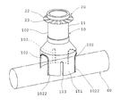
本実施例の水道仕切弁の保護カバーは、合成樹脂製末広がり状の円筒10と第1ゴムハット20と第2ゴムハット30とを備えている。
合成樹脂製末広がり状の円筒10は、円周面を白色塗装又は蛍光色塗装した硬質塩化ビニル樹脂等の公知の合成樹脂製の円筒部分100と末広がり部分101とからなり、後記第2ゴムハット30の取付位置から下方の末広がり部分101は、水道仕切弁50の上部及びフランジ511を嵌入できる大きさが必要で、末広がり部分101は図1、図3及び図4に示すように異形ソケットでもよい。
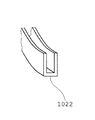
末広がり部分101の切り抜かれた穴102、102は、切縁1021、1021をゴムカバー1022、1022で外嵌することが好ましい。
また、末広がり部分101は、図3及び図4に示すように、水道仕切弁50の設置又は取替のためのフック512を設けている場合は、切り欠き穴103、103を設けることが好ましい。
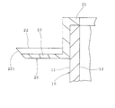
第1ゴムハット20は、図7に示すように、合成樹脂製円筒10の外周面11上部に嵌合して固着するように取りつけられるフランジ付短円筒部分21と、その下端で連設する可撓性の座金状のゴムハット縁22であって、コンクリートボックス内周面41に曲げ下げられてハット縁先221を嵌着できるようにしたものとからなる。適当数設けられる水はけ23は、ハット縁22と一体成形されているが、それよりも僅かに中心方向に短く、かつ、浅溝を形成して排水できるようにしている。また、フランジ付短円筒部分21の代わりに、特開2002−138523号の図5に示すコ字状部分21Bを円筒10の上端に嵌合して固着するように取りつけてもよい。
さらに、第1ゴムハットは、特開2002−138523号の図6に示すように、前記短円筒部分21又はコ字状部分21Bと可撓性座金状のゴムハット縁22とハット縁先211に切欠きを設けた水はけ23Bとからなるもの20Bでもよい。
第2ゴムハット30は、特開2002−138523号の図1、図7及び図8に示すように、合成樹脂製円筒10の内周面12下部に嵌合して固着する短円筒部分31と、その下端で連設する水抜き穴(図示しない)付きの円板状のゴムハット縁32とからなっている。ゴムハット縁32には開口部33が設けられ、開口部33は、水道仕切弁50のフランジカバー51の外形に嵌合するもので、ゴムハット縁32をフランジカバー51に沿って開口部33から曲げ上げることにより密着される。
従って、水道管60及び水道仕切弁50を埋設の際に、合成樹脂製末広がり円筒10を図3及び図4に示すように、水道管60に跨がるように挿入してコンクリートボックス40を設置すれば、円筒10の外周面11の上部に取りつけられた第1ゴムハット20は、コンクリートボックス40の内周面41に嵌着し、また円筒10の内周面12の下部に取りつけられた第2ゴムハット30は、水道仕切弁50のフランジカバー51に嵌着できることになる。
この場合、コンクリートボックス底版42と水道管60との間の距離は、第1ゴムハット20がコンクリートボックス40内周面を自由に移動して嵌着できることから、微少な調整が容易にできることになる。
また、コンクリートボックス40内に軽量の合成樹脂製末広がり円筒10を挿入したことから、道路面に作用する荷重は円筒10に作用せず、このため水道仕切弁50や水道管60には何らの負担がかからない。
道路から流入する水は、第1ゴムハットの水はけ23又は23Bから土砂70中に流出し、また、第2ゴムハット30の水抜き穴から土砂70中に流出する。また、道路から流入した土砂は、その殆どが第1ゴムハット20及び第2ゴムハット30上に集積するので、定期的に回収すればよい。
さらに、本発明実施例では、末広がり部分101の円径を250ミリメートルとすれば、水道管口径200ミリメートル以下の範囲はすべて末広がり円筒10で使用できることになる。
A first embodiment of the present invention will be described with reference to FIGS. 1 to 4 and FIG.
The protective cover of the water gate valve of the present embodiment includes a synthetic resin end-spreading
The synthetic resin end-spreading
It is preferable that the
Further, as shown in FIGS. 3 and 4, the
As shown in FIG. 7, the
Further, as shown in FIG. 6 of JP-A No. 2002-138523, the first rubber hat has notches formed in the short
As shown in FIGS. 1, 7 and 8 of JP-A No. 2002-138523, the
Therefore, when embedding the
In this case, the distance between the concrete box
Moreover, since the lightweight synthetic resin end-spreading
The water flowing in from the road flows out into the earth and
Further, in the embodiment of the present invention, if the diameter of the
本発明の実施例2は、図5及び図6を参照して説明する。
本実施例の水道仕切弁の保護カバーは、合成樹脂製末広がり状の円筒10Bと第1ゴムハット20と第2ゴムハット30とを備えている。
合成樹脂製末広がり状の円筒10Bは、円周面を白色塗装又は蛍光色塗装した硬質塩化ビニル樹脂等の公知の合成樹脂製の円筒部分100Bと末広がり部分101Bとからなり、後記第2ゴムハット30の取付位置から下方の末広がり部分101Bは、仕切弁カバー51B用のフランジ511Bを嵌入できる大きさが必要で、末広がり部分101Bは、円筒10Bの下方に一体的に形成したものである。
第1ゴムハット20及び第2ゴムハット30は、実施例1と同様であるので詳細説明は省略する。
従って、水道管60及び水道仕切弁50Bを埋設の際に、合成樹脂製末広がり円筒10Bを図5及び図6に示すように、水道管60に跨がるように挿入してコンクリートボックス40を設置すれば、円筒10Bの外周面11Bの上部に取りつけられた第1ゴムハット20は、コンクリートボックス40の内周面41に嵌着し、また円筒10Bの内周面12Bの下部に取りつけられた第2ゴムハット30は、水道仕切弁50Bのフランジカバー51Bに嵌着できることになる。
A second embodiment of the present invention will be described with reference to FIGS.
The protective cover of the water gate valve according to the present embodiment includes a synthetic resin end-spreading
The synthetic resin end-spreading
Since the
Therefore, when embedding the
本発明の実施例3は、図8乃至図11を参照して説明する。
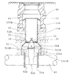
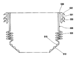
本実施例の水道仕切弁の保護カバーは、合成樹脂製の円筒本体部210に円筒下部220と円筒上部230を差し込み連結された保護カバー200と、円筒本体部210の外周面に装着自在に取りつけられ且つコンクリートボックスの内周面41に嵌着するゴムカバー300と、円筒上部230の上端部に開閉自在に取りつけられた蓋400と、保護カバー200の内周面下部に水道仕切弁50に密着させて円筒内を密閉状態に保持せしめる軟質性部材500とを備えている。
保護カバー200の円筒下部220は、実施例1及び2で説明した保護カバーと同様に末広がり状に形成することができ、保護カバー200の全体構成は、図8に示すように合成樹脂製の円筒本体部210に円筒下部220と円筒上部230を差し込むタイプとは別に一体形成されているものであっても良い。また、保護カバー200の内周面は、夜間点検を容易にするため白色塗装又は蛍光色塗装がなされていることが好ましい。
ゴムカバー300は、図8に示すように、合成樹脂製の円筒本体部210の外周面に嵌合して装着自在に取りつけられる短円筒部分310と、その上端で連設する可撓性の縁部320とからなり、コンクリートボックス内周面41に曲げ下げられて縁部320を嵌着できるようにしている。ゴムカバー300には、道路から流入する雨水等の排水を行うための浅溝状の水はけ又は切り欠き(図示省略、特開2002−138523号の図2及び図6参照)が縁部320に形成されている。なお、ゴムカバー300は、ゴム製品の代わりに、可撓性のある合成樹脂製品であっても良い。
蓋400は、合成樹脂製の円筒上部230の上端部に嵌合して開閉自在に取りつけられ、合成樹脂製円筒の円筒上部230の上端部の径をコンクリートボックスの開口部43の径よりも小さく形成することにより、開閉自在の蓋400を外部から取り出し易くすることができる。図8に示すように、例えば、円筒本体部210に直径200ミリメートルの部材を採用し、円筒上部230に直径150ミリメートルの部材を採用することにより、円筒上部230の上端部を縮小させる。本実施例では、円筒本体部210の外側に円筒上部230を取りつける施工例を示しているが、円筒本体部210の内側に収まるように加工した円筒上部230a(図示省略)を取りつけても良い。このように円筒本体部210の内側に蓋400を含めた円筒上部230aの全体が収まるように施工した場合には、蓋400の上に土砂が集積するので土砂の回収が容易になる。なお、合成樹脂製円筒の円筒上部230の上端部の径がコンクリートボックスの開口部43の径よりも大きい場合には、蓋自体の取り出しが困難になるという問題を有することになるが、蓋自体を可撓性のある軟質性素材(軟質プラスチック、軟質塩化ビニル樹脂、ゴム等)により形成することにより問題の解決を図ることができる。
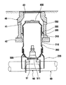
保護カバー200の円筒内を密閉状態に保持せしめる軟質性部材500は、図8及び図9に示すように、水道仕切弁50のフランジ511に密着させて固定する第1固定部510と、第1固定部510の上方に配置され蛇腹状に形成された高さ調整部520と、高さ調整部520の上方に配置され合成樹脂製の円筒本体部210と円筒下部220との接合部に嵌着させて固定する第2固定部530とから構成されている。
軟質性部材500は、密閉用のいわゆるゴムカバーとしての役割を果たすものであれば良く、ゴム又は軟質塩化ビニル樹脂等の軟質性のある素材を加工して成形される。また、軟質性部材500の全体構成は、図8及び図9に示すように水道仕切弁50のフランジ511に密着させて固定するタイプに限定されず、水道仕切弁50を取り巻く形状で袋状に成形して水密性を保持できるものであれば良い。
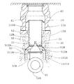
軟質性部材500の第1固定部510は、水道管60の口径50ミリメートル、75ミリメートル、100ミリメートルに対応して水道仕切弁50のフランジ部分が大きくなることから、いずれの形状の水道仕切弁50にも対応できるようにするため、図9に示すように下方に向かって径が順次減少する形状に形成され、内周面には半円状又は三角形状の突起515が3箇所設けられている。この半円状又は三角形状の突起515を水道仕切弁50のフランジ511に食い込ますことにより固定される。ここで、突起515の形状については、三角形状のように鋭角である方が取りつけ易くなる。また、図10に示すようにステンレス製の固定バンド516を使用して取りつけを強固にしても良い。
軟質性部材500の高さ調整部520は、図9に示すように第1固定部510の上方に配置され蛇腹状に形成されている。これにより、施工する際に水道仕切弁50との間隔や位置関係にばらつきがある場合でも対応が可能になる。
軟質性部材500の第2固定部530は、図9に示すように高さ調整部520の上方に配置され、合成樹脂製の円筒本体部210と円筒下部220との接合部に嵌着させることにより固定され、それと同時に水密性が保持される。
第2固定部530の構成は、図9及び図10に示すように上端部を外側に屈曲させて形成したコ字状の挟持部531からなり、この挟持部531の内部には円筒下部220の上端部が差し込まれるようになっている。また、挟持部531の外側部の外周面には、円筒本体部210の下端部を差し込み易くし且つ水密性を高めるためのハット状又は半円状の突起532が複数個設けられている。また、図9に示すようにハット状又は半円状の突起532の間隙には、水分を吸収して膨張するいわゆる膨張ゴムリング533と称する部材を装着することができる。ただし、このような膨張ゴムリング533がなくても水密性の保持は可能であるが、膨張ゴムリング533を取りつけることにより完全な止水が可能となる。
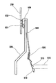
上記は、円筒本体部210と円筒下部220との接合部について、円筒下部220の上端部の外側に円筒本体部210の下端部を差し込むタイプにおける軟質性部材500の具体的構成を説明したが、円筒下部220の上端部の内側に円筒本体部211の下端部を差し込むタイプにおける別の軟質性部材の具体的構成を、図11に基づいて説明する。
軟質性部材600は、図11に示すように、水道仕切弁50のフランジ511に密着させて固定する第1固定部610と、第1固定部610の上方に配置され蛇腹状に形成された高さ調整部620と、高さ調整部620の上方に配置され合成樹脂製の円筒本体部211と円筒下部220との接合部に嵌着させて固定する第2固定部630とから構成されている。ここで、第1固定部610と高さ調整部620は、上述した第1固定部510と高さ調整部520と同様であるので説明は省略する。
軟質性部材600の第2固定部630は、上記と同様に合成樹脂製の円筒本体部211と円筒下部220との接合部に嵌着させることにより固定され、それと同時に水密性が保持される。
第2固定部630の構成は、図11に示すように上端部を外側に屈曲させて形成したコ字状の挟持部631からなり、挟持部631の内部には円筒下部220の上端部が差し込まれるようになっている。挟持部631の内側部の内周面及び外周面にハット状又は半円状の突起632が複数個設けられている。、この挟持部631の内側部の内周面に設けられたハット状又は半円状の突起632に沿って円筒本体部211の下端部が差し込まれるようになっている。
以上のように、本実施例の水道仕切弁の保護カバーは、合成樹脂製の保護カバー200の上端部に開閉自在の蓋400を備え、保護カバー200の内周面下部に水道仕切弁50に密着させて当該円筒内を密閉状態に保持せしめる軟質性部材500・600を介在させることにより、道路面からの土砂流入を防止し且つ地下水流入を完全に防止することができるため、水道仕切弁50の保護を強化することが可能になるのである。
なお、軟質性部材500・600については、水道仕切弁50に密着させて当該円筒内を密閉状態に保持せしめる役割を果たすものであれば良いため、上述した第1固定部510・610、第2固定部530・630の形状・構造については、水道仕切弁の保護カバー及び水道仕切弁の種類・形状・構造などに対応させて適宜変更することができる。例えば、接着手段を用いて水道仕切弁の保護カバー及び水道仕切弁に取りつけることも考えられる。また、水密性を保持することができる他の構成を採用すれば、上述した挟持部531・631の形状・構造を簡素化することも可能である。
A third embodiment of the present invention will be described with reference to FIGS.
The protective cover for the water gate valve of the present embodiment is attached to the outer peripheral surface of the cylindrical
The cylindrical
As shown in FIG. 8, the
The
As shown in FIGS. 8 and 9, the
The
The
As shown in FIG. 9, the
As shown in FIG. 9, the
9 and 10, the
The above describes the specific configuration of the
As shown in FIG. 11, the
The
As shown in FIG. 11, the
As described above, the protective cover of the water gate valve of the present embodiment includes the
The
本発明の水道仕切弁の保護カバーは、安価に量産できる。 The protective cover of the water gate valve of the present invention can be mass-produced at low cost.
10、10B 保護カバー
100、100B 円筒部分
101、101B 末広がり部分
11、11B 円筒部分の外周面
12、12B 円筒部分の内周面
20 第1ゴムハット
30 第2ゴムハット
40 コンクリートボックス
41 コンクリートボックスの内周面
43 コンクリートボックスの開口部
50、50B 水道仕切弁
51、51B 水道仕切弁のフランジカバー
60 水道管
200 保護カバー
210 円筒本体部
220 円筒下部
230 円筒上部
300 ゴムカバー
400 蓋
500、600 軟質性部材
DESCRIPTION OF
Claims (7)
Priority Applications (1)
| Application Number | Priority Date | Filing Date | Title |
|---|---|---|---|
| JP2004335238A JP4036379B2 (en) | 2004-03-08 | 2004-11-19 | Protective cover for water gate valve |
Applications Claiming Priority (2)
| Application Number | Priority Date | Filing Date | Title |
|---|---|---|---|
| JP2004063760 | 2004-03-08 | ||
| JP2004335238A JP4036379B2 (en) | 2004-03-08 | 2004-11-19 | Protective cover for water gate valve |
Publications (2)
| Publication Number | Publication Date |
|---|---|
| JP2005290969A true JP2005290969A (en) | 2005-10-20 |
| JP4036379B2 JP4036379B2 (en) | 2008-01-23 |
Family
ID=35324208
Family Applications (1)
| Application Number | Title | Priority Date | Filing Date |
|---|---|---|---|
| JP2004335238A Expired - Fee Related JP4036379B2 (en) | 2004-03-08 | 2004-11-19 | Protective cover for water gate valve |
Country Status (1)
| Country | Link |
|---|---|
| JP (1) | JP4036379B2 (en) |
Cited By (5)
| Publication number | Priority date | Publication date | Assignee | Title |
|---|---|---|---|---|
| WO2011006215A1 (en) * | 2009-07-16 | 2011-01-20 | Anthony Richard Humphreys | Barrier device for water reticulation component |
| KR101128268B1 (en) * | 2009-07-28 | 2012-03-26 | 주식회사 미래산업 | The waterworks meter cover can insulation absence collection of sealing up construction |
| KR101575600B1 (en) * | 2015-04-08 | 2015-12-22 | 이동헌 | Gate valve integral protecting cover |
| AU2009213106B2 (en) * | 2009-07-16 | 2016-10-20 | Anthony Richard Humphreys | A Fire Hydrant Insect Seal |
| KR101785432B1 (en) * | 2017-03-30 | 2017-10-16 | (주) 디케이금속 | Cover for regulating valve having valve key guide |
-
2004
- 2004-11-19 JP JP2004335238A patent/JP4036379B2/en not_active Expired - Fee Related
Cited By (5)
| Publication number | Priority date | Publication date | Assignee | Title |
|---|---|---|---|---|
| WO2011006215A1 (en) * | 2009-07-16 | 2011-01-20 | Anthony Richard Humphreys | Barrier device for water reticulation component |
| AU2009213106B2 (en) * | 2009-07-16 | 2016-10-20 | Anthony Richard Humphreys | A Fire Hydrant Insect Seal |
| KR101128268B1 (en) * | 2009-07-28 | 2012-03-26 | 주식회사 미래산업 | The waterworks meter cover can insulation absence collection of sealing up construction |
| KR101575600B1 (en) * | 2015-04-08 | 2015-12-22 | 이동헌 | Gate valve integral protecting cover |
| KR101785432B1 (en) * | 2017-03-30 | 2017-10-16 | (주) 디케이금속 | Cover for regulating valve having valve key guide |
Also Published As
| Publication number | Publication date |
|---|---|
| JP4036379B2 (en) | 2008-01-23 |
Similar Documents
| Publication | Publication Date | Title |
|---|---|---|
| JP4036379B2 (en) | Protective cover for water gate valve | |
| JP2021055518A (en) | Roof repair sheet | |
| JP4846508B2 (en) | Control valve for fluid pipe | |
| KR20090046117A (en) | A structure and method of connecting underground-pipe | |
| KR100623240B1 (en) | Manhole integrated with drainage | |
| US5802787A (en) | Grommet seal for roof flashing | |
| JP2007269405A (en) | Junction structure for covering lid | |
| KR100849527B1 (en) | Pipe connection part of manhole | |
| JP2018031196A (en) | Drain piping and construction method for the same | |
| JP2017210969A (en) | Check valve | |
| JP2006200311A (en) | Joint structure of buried structure and flexible joint used therefor | |
| JP4585942B2 (en) | Still water joint material | |
| KR200344491Y1 (en) | Saddle | |
| JPH0523649Y2 (en) | ||
| JP4582555B2 (en) | Water supply, sewerage or gas lid structure | |
| JP3314340B2 (en) | Non-return valve with slitted cover used for water-blocking sheets for civil engineering | |
| JP2555747Y2 (en) | Drain masu mounting device | |
| JP3991338B2 (en) | How to connect U-shaped groove to ridge or side groove | |
| JPH09242170A (en) | Connecting structure of outdoor drain pipe and drainage basin | |
| JP4608295B2 (en) | Gas pipe valve protector | |
| JP4094527B2 (en) | Seal joint for joints | |
| JP3899226B2 (en) | Protective cover for water gate valve | |
| KR200336587Y1 (en) | A Water-Proof Cover for a Manhole | |
| KR100486151B1 (en) | Spiral Hose Using Polyethylene | |
| KR200432034Y1 (en) | structure shut tight of a manhole |
Legal Events
| Date | Code | Title | Description |
|---|---|---|---|
| A621 | Written request for application examination |
Free format text: JAPANESE INTERMEDIATE CODE: A621 Effective date: 20070212 |
|
| A871 | Explanation of circumstances concerning accelerated examination |
Free format text: JAPANESE INTERMEDIATE CODE: A871 Effective date: 20070212 |
|
| A975 | Report on accelerated examination |
Free format text: JAPANESE INTERMEDIATE CODE: A971005 Effective date: 20070312 |
|
| A131 | Notification of reasons for refusal |
Free format text: JAPANESE INTERMEDIATE CODE: A131 Effective date: 20070419 |
|
| A521 | Request for written amendment filed |
Free format text: JAPANESE INTERMEDIATE CODE: A523 Effective date: 20070608 |
|
| A131 | Notification of reasons for refusal |
Free format text: JAPANESE INTERMEDIATE CODE: A131 Effective date: 20070731 |
|
| A521 | Request for written amendment filed |
Free format text: JAPANESE INTERMEDIATE CODE: A523 Effective date: 20070801 |
|
| TRDD | Decision of grant or rejection written | ||
| A01 | Written decision to grant a patent or to grant a registration (utility model) |
Free format text: JAPANESE INTERMEDIATE CODE: A01 Effective date: 20071010 |
|
| A61 | First payment of annual fees (during grant procedure) |
Free format text: JAPANESE INTERMEDIATE CODE: A61 Effective date: 20071026 |
|
| R150 | Certificate of patent or registration of utility model |
Ref document number: 4036379 Country of ref document: JP Free format text: JAPANESE INTERMEDIATE CODE: R150 |
|
| FPAY | Renewal fee payment (event date is renewal date of database) |
Free format text: PAYMENT UNTIL: 20101109 Year of fee payment: 3 |
|
| FPAY | Renewal fee payment (event date is renewal date of database) |
Free format text: PAYMENT UNTIL: 20101109 Year of fee payment: 3 |
|
| FPAY | Renewal fee payment (event date is renewal date of database) |
Free format text: PAYMENT UNTIL: 20131109 Year of fee payment: 6 |
|
| R250 | Receipt of annual fees |
Free format text: JAPANESE INTERMEDIATE CODE: R250 |
|
| R250 | Receipt of annual fees |
Free format text: JAPANESE INTERMEDIATE CODE: R250 |
|
| R250 | Receipt of annual fees |
Free format text: JAPANESE INTERMEDIATE CODE: R250 |
|
| R250 | Receipt of annual fees |
Free format text: JAPANESE INTERMEDIATE CODE: R250 |
|
| R250 | Receipt of annual fees |
Free format text: JAPANESE INTERMEDIATE CODE: R250 |
|
| R250 | Receipt of annual fees |
Free format text: JAPANESE INTERMEDIATE CODE: R250 |
|
| R250 | Receipt of annual fees |
Free format text: JAPANESE INTERMEDIATE CODE: R250 |
|
| LAPS | Cancellation because of no payment of annual fees |