JP2005290873A - Housing body with opening/closing door - Google Patents
Housing body with opening/closing door Download PDFInfo
- Publication number
- JP2005290873A JP2005290873A JP2004108495A JP2004108495A JP2005290873A JP 2005290873 A JP2005290873 A JP 2005290873A JP 2004108495 A JP2004108495 A JP 2004108495A JP 2004108495 A JP2004108495 A JP 2004108495A JP 2005290873 A JP2005290873 A JP 2005290873A
- Authority
- JP
- Japan
- Prior art keywords
- opening
- closing door
- door
- guide
- open
- Prior art date
- Legal status (The legal status is an assumption and is not a legal conclusion. Google has not performed a legal analysis and makes no representation as to the accuracy of the status listed.)
- Pending
Links
Images


Landscapes
- Support Devices For Sliding Doors (AREA)
Abstract
Description
本願は、物を収容するための開閉扉付き収容体に関する。 The present application relates to a container with an opening / closing door for accommodating an object.
従来、例えば、洋服等を収容するための開閉扉付き収容体70は、図15に示すように、前面が開口した箱型のケース本体71と、ケース本体71の開口を開閉する開閉扉72、72と、を備える。
Conventionally, for example, as shown in FIG. 15, a
ケース本体71の開口の上部及び下部には左右方向に開閉扉72がスライドするためのスライドレール73、73が設けられている。開閉扉72は、2枚の板体を一対として、開口の左右に設けられている。また、2枚の板体は、ヒンジ74により連結されている。また、一方の開閉扉72の側部はヒンジ75によりケース本体71に取り付けられている。また、他方の開閉扉72のコーナ部には、スライドレール73と連結するための連結体76、76が設けられている。この連結体76は前後方向に回動する。
これにより、収容体70を開口する場合には、開閉扉72を左右方向に力を加えることにより、ヒンジ74によって、2枚の板体が前方に張り出すように折り畳まれて、連結体76がスライドレール73に沿って移動し、開口する。一方、開閉扉72を閉じる場合には、開閉扉72をガイドレール73の中心方向に力を加えることにより、連結体76がスライドレール73に沿って移動し、ヒンジ74によって、2枚の板体が平坦となって開口を閉じることができる。
Thereby, when opening the
しかしながら、このような従来の手段等では、開閉時に開閉扉が前方に張り出すために開閉扉が邪魔になるという問題があった。 However, such a conventional means has a problem that the door is obstructed because the door is projected forward when the door is opened and closed.
また、一般に収容体はその形状を変更できないので、引越し等においては、家の形状に合わせて収容体を設置するしか方法がなかった。これにより、家主の設置したい場所に収容体が上手く収まらない場合もあり、そのような場合には、設置場所に合わせて収容体を買い換える必要があった。 In general, since the shape of the container cannot be changed, the only way to move is to install the container in accordance with the shape of the house. As a result, the container may not fit well in the place where the landlord wants to install. In such a case, it is necessary to replace the container in accordance with the installation location.
そこで、本願は上記各問題点の解決を課題の一例として為されたもので、収容体の大きさを設置場所に合わせて変更可能であって、開閉時に開閉扉が邪魔にならない開閉扉付き収容体を提供することを目的とする。 Therefore, the present application was made as an example of solving the above problems, and the size of the container can be changed according to the installation location, and the door with the door that does not interfere with the door when opening and closing is provided. The purpose is to provide a body.
上記課題を解決するために、請求項1に記載の開閉扉付き収容体は、収容物を収容するための開口(2)を有し、少なくとも支持体(20)を含んで形成されるケース本体(3)と、前記開口を開閉するための開閉扉(7)と、前記ケース本体の外周に沿って形成されるとともに前記開閉扉をガイドするためのガイド手段(5、6)と、を具備し、前記支持体は、複数の支持体(20a、20b)から構成され、前記1の支持体に対して他の支持体が摺動して伸縮可能に設けられるとともに、前記支持体を固定して前記支持体の長さを調整するための調整手段(23)を備え、前記開閉扉は、複数の板体(7a)を蛇腹状に形成しているとともに、少なくとも前記開閉扉のガイド方向における前記開口の長さを有し、前記ガイド手段は、複数のガイド部材(31、32)を備え、前記1のガイド部材に対して他のガイド部材が摺動して伸縮可能に設けられるとともに、前記開閉扉のガイド方向における前記開口の長さの少なくとも倍の長さを有することを特徴とする。
In order to solve the above-mentioned problem, a case body having an opening and closing door according to
以下、本願の最良の実施形態について、図1乃至図13を用いて詳細に説明する。なお、以下に説明する実施の形態は、洋服等を収容するための開閉扉付き収容体として説明するが、当該洋服等を収容するための開閉扉付き収容体に限定されるものではなく、一般的な物置等としても適用できる。 Hereinafter, the best embodiment of the present application will be described in detail with reference to FIGS. In addition, although embodiment described below demonstrates as a container with an opening / closing door for accommodating clothes etc., it is not limited to the container with an opening / closing door for accommodating the said clothes, etc. It can also be applied as a typical storeroom.
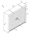
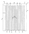
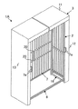
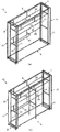
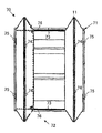
図1は開閉扉付き収容体の外観を示す斜視図、図2は開閉扉付き収容体の正面図、図3は背面図、図4は右側面図、図5は平面図、図6は底面図である。なお、左側面図は右側面図と同じなので省略する。また、図7はケース本体の内部構造図、図8はガイド部材を示し、図8(a)は図7のA部分の拡大図、図8(b)は図8(a)のD−D断面図、図8(c)は図7のC部分の拡大図、図9は図7のB拡大図、図10は連結体を示し、図10(a)は連結体の正面図、図10(b)は連結体の左側面図、図10(c)は連結体を開閉扉に取り付けた図である。また、図11は開閉扉を開けた際の状態を示す斜視図である。さらに、図12はケース本体を左右方向に縮めた際の状態を示す斜視図、図13は図12において開閉扉を開けた状態を示す斜視図である。また、本実施形態では、説明し易いように、図2の上下左右方向を本願の開閉扉付き収容体の上下左右方向として説明するが、本願の開閉扉付き収容体の実施形態がこの実施形態に限定されるものではない。 1 is a perspective view showing the exterior of a container with an opening / closing door, FIG. 2 is a front view of the container with an opening / closing door, FIG. 3 is a rear view, FIG. 4 is a right side view, FIG. 5 is a plan view, and FIG. FIG. Since the left side view is the same as the right side view, it is omitted. 7 is an internal structural view of the case main body, FIG. 8 shows a guide member, FIG. 8A is an enlarged view of portion A in FIG. 7, and FIG. 8B is a DD in FIG. FIG. 8C is an enlarged view of a portion C in FIG. 7, FIG. 9 is an enlarged view of B in FIG. 7, FIG. 10 shows a connecting body, FIG. 10A is a front view of the connecting body, FIG. FIG. 10B is a left side view of the coupling body, and FIG. 10C is a diagram in which the coupling body is attached to the opening / closing door. FIG. 11 is a perspective view showing a state when the open / close door is opened. Furthermore, FIG. 12 is a perspective view showing a state when the case main body is contracted in the left-right direction, and FIG. 13 is a perspective view showing a state where the open / close door is opened in FIG. Further, in this embodiment, for ease of explanation, the up, down, left, and right directions in FIG. 2 are described as the up, down, left, and right directions of the container with an opening / closing door of the present application. It is not limited to.
先ず、図1〜図11を参照して、本願に係る開閉扉付き収容体の構成について説明する。 First, with reference to FIGS. 1-11, the structure of the container with an opening / closing door which concerns on this application is demonstrated.
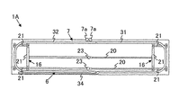
図示のように、開閉扉付き収容体1Aは、前面に洋服等の収容物を収容するための開口2を有する箱型のケース本体3と、ケース本体3の外周に沿って形成されるとともに、ケース本体2の上部および下部に取り付けられる開閉扉7を案内(以下、「ガイド」と称する。)するための一対のガイドレール5、6と、一対のガイドレール5、6に支持されるケース本体3の開口2を開閉するための取手7aを有する開閉扉7と、を備えている。また、ケース本体3には、見栄えを良くするために略矩形状の板体11、12、13によってケース本体3の上面、側面が覆われている。また、ケース本体の上面に設けられる板体11は、左右及び真ん中の3枚の板体からなり、真ん中の板体11aは取り外し可能に設けられている。ケース本体3の幅方向を縮める際に当該板体11aは取り外される。なお、本実施形態におけるガイドレール5、6は本発明のガイド手段として機能する。
As shown in the figure, a
ケース本体3は、床面から垂設される一対の側体16、16と、一対の側体16の上方、及び下方に一対の側体16に対して垂設して両方の側体16を繋ぐ支持体20、20、20と、を備える。側体16は、複数の支持体21、21、…、21により枠組みが形成されている。このようにして形成されたケース本体3は、箱型形状の骨組み構造に形成されている。
The
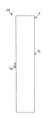
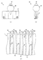
また、支持体20は、図9に示すように、2つの支持体20a、20bから構成される。この支持体20a、20bは円筒形状であり、一方の支持体20aに対し他方の支持体20bの直径は小さく形成されている。これにより、一方の支持体20aに対して他方の支持体20bが摺動して伸縮可能である。また、前記一方の支持体20aの一部(先端近傍)には支持体20aの中央に貫通する貫通孔22を有し、当該貫通孔22にはネジ部23aを有するつまみ23が取り付けられる。当該つまみ23を回転することにより、ネジ部23aが一方の支持体20aを貫通し、当該他方の支持体20bの一部を押圧する。これにより、支持体20bを固定し、支持体20の長さを調節することができる。なお、本実施形態におけるつまみ23は、本発明の長さ調整手段として機能する。
Moreover, the
ケース本体3の上部に取り付けられるガイドレール5は、一対のU字状のガイド部材25、26により形成されている。ガイド部材25、26は、断面形状がC状の溝27を有する(図8(c))。この溝27はガイドレール5の底面に形成されている。また、一方のガイド部材26の隣には、ガイドレール5の底面に溝27が形成されている所定の長さを有するガイド部材28が並べて配置されている(図7)。
The
また、一方のガイド部材26の外径は他方のガイド部材25の外径よりも大きく形成され、一方のガイド部材26の端部は他方のガイド部材25の端部と接続される。その際、他方のガイド部材25の一方の端部は、他方のガイド部材体26と並べて配置されたガイド部材28の端部に接続される。これにより、他方のガイド部材25は、一方のガイド部材26、及びガイド部材28下部を摺動しスライド移動できるので、ガイドレール5は左右方向に自由に伸縮できる。
The outer diameter of one
一方、ケース本体3の下部に取り付けられるガイドレール6は、図8(a)に示すように、一対のU字状のガイド部材31、32により形成されている。ガイド部材31、32は、断面形状がC状の溝33を有する(図8(b))。この溝33は上部に形成されている。また、一方のガイド部材32の隣には、上部に溝33が形成されている所定の長さを有するガイド部材34が並べて配置されている(図6、図7)。
On the other hand, the
また、一方のガイド部材32の外径は他方のガイド部材31の外径よりも大きく形成され、一方のガイド部材32の端部は他方のガイド部材31の端部と接続される。その際、他方のガイド部材31の一方の端部は、他方のガイド部材31と並べて配置されたガイド部材34の端部に接続される。これにより、他方のガイド部材31は、一方のガイド部材32上を摺動しスライド移動できるので、ガイドレール5と同様に、ガイドレール6も左右方向に自由に伸縮できる。
The outer diameter of one
なお、ガイドレール5、6は、開閉扉7のガイド方向におけるケース本体3の開口2の長さの少なくとも倍の長さを有している必要がある。このようにすれば、開閉扉7は開口2を完全に開閉することができる。
The guide rails 5 and 6 need to have a length at least twice the length of the
また、ガイドレール5、6は、支持体20を縮めるとともに開閉扉7を開いた状態において、開閉扉7の少なくとも一部がケース本体3の背面で重なるように配置されているとよい。このようにすれば、支持体を縮めても開閉扉7は開口2を完全に開閉することができる。
In addition, the
開閉扉7は、略矩形上の板体7aが複数並べて形成されている。板体7aと板体7aとの間には、上下方向全長にわたって1の板体7aが他の板体7aと独立して回動するための連結部材35がそれぞれ備えられている。即ち、開閉扉7は、複数の板体7aを蛇腹状に形成している。これにより、ガイドレール5、6が曲折していても、開閉扉7はガイドレール5、6から脱落することなく曲がることができる。
The open /
また、開閉扉7の左右方向の長さは、ガイド方向におけるケース本体3の開口2の長さを有している。
Further, the length of the open /
また、連結部材35の上部、及び下部には、ガイドレール5、6の溝27、33と連結するための連結体40を備えている。図10に示すように、連結体40は、開閉扉7の所定の2枚の板体7aのコーナ部を挟みこんで支持するための一対の支持板41と、支持板41からガイドレール5、6側へ突出して設けられるピン42と、ピン42の軸42a上を矢印に示すように摺動する円形状の摺動部材43と、を備えている。また、ピン42の先端は摺動部材43の脱落を防止するために軸42aの径より少し大きく形成されている。また、連結体40の摺動部材43と支持板41との間にはガイドレール5、6の溝27、33が嵌合する。
In addition, a connecting
このように、連結体40の先端(摺動部材43)がこのガイドレール5、6の溝27、33と嵌合することにより、開閉扉7をガイドレール5、6にしっかりと連結することができるとともに開閉扉7をガイドレール5、6に沿って所定のガイド方向に容易に摺動(移動)できる。また、開閉扉7の開閉時において、連結体40がガイドレール5、6の溝27、33から脱落するのを防止できる。また、連結体40と開閉扉7との間に弾性体を備え、上下に多少伸縮できるようにすると良い。これにより、ガイドレール5、6の溝27、33に対して開閉扉7を容易に脱着できる。
As described above, the opening /
また、連結体40は1の板体7aと他の板体7aとの間であって開閉扉7の端部に取り付けられている。このようにすれば、開閉扉7の開閉時に、開閉扉7の板体7aが折り畳まれることがない。
Further, the connecting
次に、本実施形態の開閉扉の開閉動作について図1、及び図11を用いて説明する。 Next, the opening / closing operation | movement of the opening / closing door of this embodiment is demonstrated using FIG.1 and FIG.11.
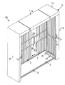
まず、支持体20が最大長さに調整されている場合の開閉扉の開閉動作について説明する。図1に示す右側の開閉扉7に有する取手7aを持って右方向に力を加えることにより、開閉扉7が連結体40を介しガイドレール5に沿って摺動する。開閉扉7は、ケース本体3の背面へとガイドされ、ケース本体3の開口2の右半分が開口する。一方、左側の開閉扉7も同様に取手7aを持って左方向に力を加えることにより、開閉扉7が連結体40を介してガイドレール5に沿って摺動する。開閉扉7は、ケース本体3の背面へとガイドされ、ケース本体3の左半分が開口し、図11に示すように、ケース本体3が全開する。
First, the opening / closing operation | movement of the opening / closing door in case the
このように、支持体20が最大長さに調整されている場合には、特に問題がないが、支持体20を縮めた場合には、ガイドレール5の長さが足りずにケース本体3の開口2を全開することができなくなることが考えられる。そこで、本願は、ケース本体3の背面において、ガイドレール5の両端部近傍を並べて配置している。このようにすれば、左右の開閉扉7はケース本体3の背面において重なるように配置(収納)され、ケース本体3の開口を全開することができる。
Thus, when the
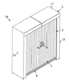
なお、ケース本体3の幅を最小に縮める場合には、支持体20の1の支持体に対して他の支持体を摺動させることにより支持体20を縮める。また、ケース本体3が幅方向に複数の支持体20を備えていれば、当該支持体20を同様に縮めるとともに、ガイドレール5も同様に縮ませる。そして中板11aを取り外すことにより、図12に示すように、ケース本体3を幅方向に縮めることができる。
In order to reduce the width of the
図12に示すように、ケース本体3の幅を最小に縮めた状態において、開閉扉7を開ける際には、上記と同様に、左右の開閉扉7をそれぞれの方向に摺動させることで全開できる(図13)。その際、左右の開閉扉7はケース本体3の背面において重なって配置される。
As shown in FIG. 12, when opening the opening /
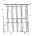
次に、本願の開閉扉付き収容体の他の実施の形態について図14を用いて説明する。図14は他の実施例の収容体の内部構造を示し、図14(a)は第1実施例、図14(b)は第2実施例である。なお、最良の実施形態と同じ部分には同一符号を付し、説明を省略する。 Next, another embodiment of the container with an opening / closing door of the present application will be described with reference to FIG. FIG. 14 shows the internal structure of a container according to another embodiment. FIG. 14 (a) shows the first embodiment, and FIG. 14 (b) shows the second embodiment. In addition, the same code | symbol is attached | subjected to the same part as best embodiment, and description is abbreviate | omitted.
本実施形態の開閉扉付き収容体1Bは、図14(a)に示すように、ケース本体3の上部には水平方向に一対の側体16を繋ぐ支持体55を複数、備えている。また、ケース本体3の下部には、略L字状の支持体56を一方の側体16から水平方向に備えている。このようにすれば、当該支持体55、56に、例えば、洋服がかけられた衣紋かけをかけることができ、洋服等を整理して収容することができる。
As shown in FIG. 14A, the container 1B with an opening / closing door of the present embodiment includes a plurality of supports 55 that connect the pair of
また、図14(b)に示すように、本実施形態の開閉扉付き収容体1Cは、両側体16の間に床面から垂設して略H形状の支持体57を設けるようにしてもよい。さらに、当該支持体57と一方の側体16とを繋ぐ支持体58を備えるようにしてもよい。このようにすれば、ケース本体3の剛性を高めることもできる。さらに、ケース本体3の内部を仕切ることも可能である。
Further, as shown in FIG. 14B, the container 1C with an open / close door of the present embodiment may be provided with a substantially H-shaped support body 57 suspended from the floor surface between both
また、所定の支持体20、55、56、57、58や側体16と連結して適宜必要な箇所に支持体を備えるようにしてもよい。
Moreover, it may connect with the predetermined |
また、支持体は他の支持体や側体とねじ等の固定具により取り外し可能に取り付けられ、分解、組立てが容易にできるように形成されていることが好ましい。 Further, it is preferable that the support is detachably attached to another support or side body by a fixing tool such as a screw, and is formed so as to be easily disassembled and assembled.
以上説明したように、上記実施形態によれば、本願に係る開閉扉付き収容体1Aは、収容物を収容するための開口2を有し、少なくとも支持体20を含んで形成されるケース本体3と、前記開口2を開閉するための開閉扉7と、前記ケース本体3の外周に沿って形成されるとともに前記開閉扉7をガイドするためのガイドレール5、6と、を具備し、前記支持体20は、複数の支持体から構成され、前記1の支持体に対して他の支持体が摺動して伸縮可能に設けられるとともに、前記支持体の長さを調節するための長さ調節手段を備え、前記開閉扉7は、蛇腹状の板体7aであって、少なくとも前記開閉扉7のガイド方向における前記開口2の長さを有し、前記ガイドレール5、6は、複数のガイド部材31、32から構成され、前記1のガイド部材32に対して他のガイド部材31が摺動して伸縮可能に設けられるとともに、前記開閉扉7のガイド方向における前記開口2の長さの少なくとも倍の長さを有する。このようにすれば、ケース本体の大きさを自由に変更できるとともに、ケース本体の大きさを最小にした場合においても、開閉扉を全開することができる。
As described above, according to the above-described embodiment, the
また、前記開閉扉7とガイドレール5、6との間に連結体40を備え、前記連結体40は前記1の板体7aと他の板体7aとの間であって前記開閉扉7の端部に取り付けられている。このようにすれば、開閉扉7がガイドレール5、6に沿って移動する最中に、開閉扉7の板体7aが折り畳まれることなく、ガイドレール5、6に沿って開閉扉7を移動できる。
Further, a connecting
また、ガイドレール5、6は、支持体20を縮めるとともに開閉扉7を開いた状態において、開閉扉7の少なくとも一部がケース本体3の背面で重なるように配置されている。このようにガイドレール5、6は、ケース本体3の背面において一方の端部近傍と他方の端部近傍とが並べて配置されるので、ガイドレールの長さを容易に長くとることができ、支持体20を縮めても開閉扉7は開口2を完全に開口することができる。また、ガイドレール5、6は、ケース本体3の上部と下部に取り付けられている。このようにすれば、開閉扉7をしっかりと支持しつつガイドすることができる。
The guide rails 5 and 6 are arranged such that at least a part of the opening /
なお、本実施形態は一形態であって、この形態に限定されるものではない。例えば、支持体20、21は円筒形状に限定される必要はなく、角筒形状等であってもよい。また、開閉扉7は板材に限定される必要はなく、プラスチック材等の材料であっても構わない。
In addition, this embodiment is one form and is not limited to this form. For example, the
2 開口
5、6 ガイドレール
7 開閉扉
7a 板体
20、20a、20b 支持体
23 つまみ
31、32 ガイド部材
2
Claims (4)
前記開口を開閉するための開閉扉と、
前記ケース本体の外周に沿って形成されるとともに前記開閉扉をガイドするためのガイド手段と、
を具備し、
前記支持体は、複数の支持体を備え、前記1の支持体に対して他の支持体が摺動して伸縮可能に設けられるとともに、前記支持体の長さを調節するための長さ調節手段を備え、
前記開閉扉は、蛇腹状の板体であって、少なくとも前記開閉扉のガイド方向における前記開口の長さを有し、
前記ガイド手段は、複数のガイド部材を備え、前記1のガイド部材に対して他のガイド部材が摺動して伸縮可能に設けられるとともに、前記開閉扉のガイド方向における前記開口の長さの少なくとも倍の長さを有することを特徴とする開閉扉付き収容体。 A case main body having an opening for accommodating the contents and including at least a support;
An opening and closing door for opening and closing the opening;
Guide means formed along the outer periphery of the case body and for guiding the open / close door;
Comprising
The support body includes a plurality of support bodies, and the other support body is slidable with respect to the one support body so as to be extendable and contracted, and the length adjustment for adjusting the length of the support body With means,
The open / close door is a bellows-like plate, and has at least the length of the opening in the guide direction of the open / close door,
The guide means includes a plurality of guide members, the other guide members slide relative to the one guide member, and can be extended and contracted, and at least the length of the opening in the guide direction of the opening / closing door. A container with an opening and closing door characterized by having a double length.
前記連結体は前記1の板体と他の板体との間であって前記開閉扉の端部に取り付けられていることを特徴とする請求項1に記載の開閉扉付き収容体。 A connecting body is provided between the opening / closing door and the guide means,
2. The container with an opening / closing door according to claim 1, wherein the connection body is attached to an end portion of the opening / closing door between the one plate body and the other plate body.
Priority Applications (1)
| Application Number | Priority Date | Filing Date | Title |
|---|---|---|---|
| JP2004108495A JP2005290873A (en) | 2004-03-31 | 2004-03-31 | Housing body with opening/closing door |
Applications Claiming Priority (1)
| Application Number | Priority Date | Filing Date | Title |
|---|---|---|---|
| JP2004108495A JP2005290873A (en) | 2004-03-31 | 2004-03-31 | Housing body with opening/closing door |
Publications (1)
| Publication Number | Publication Date |
|---|---|
| JP2005290873A true JP2005290873A (en) | 2005-10-20 |
Family
ID=35324117
Family Applications (1)
| Application Number | Title | Priority Date | Filing Date |
|---|---|---|---|
| JP2004108495A Pending JP2005290873A (en) | 2004-03-31 | 2004-03-31 | Housing body with opening/closing door |
Country Status (1)
| Country | Link |
|---|---|
| JP (1) | JP2005290873A (en) |
Cited By (1)
| Publication number | Priority date | Publication date | Assignee | Title |
|---|---|---|---|---|
| KR101081496B1 (en) * | 2011-06-15 | 2011-11-08 | 이영우 | Firearms |
-
2004
- 2004-03-31 JP JP2004108495A patent/JP2005290873A/en active Pending
Cited By (1)
| Publication number | Priority date | Publication date | Assignee | Title |
|---|---|---|---|---|
| KR101081496B1 (en) * | 2011-06-15 | 2011-11-08 | 이영우 | Firearms |
Similar Documents
| Publication | Publication Date | Title |
|---|---|---|
| US7187554B2 (en) | Movable console device | |
| WO2018130126A1 (en) | Storage rack and refrigerator having the storage rack | |
| CN109715011A (en) | Pull-out frame for cabinet furniture | |
| JP2005290873A (en) | Housing body with opening/closing door | |
| CN110167393B (en) | Corner cabinet accessories for gear-controlled movement support of pallets in corner cabinets | |
| JP3913759B2 (en) | Door opening / closing mechanism | |
| EP3438389B1 (en) | Sliding apparatus for sliding door | |
| US5231711A (en) | Apparatus for opening and closing folding bed | |
| KR20180025726A (en) | Furniture having expandable table | |
| KR200410198Y1 (en) | Rotatable sliding door device | |
| JP6877267B2 (en) | Folding door unit | |
| JP2007014685A (en) | Walker | |
| JP6740149B2 (en) | Console drawer | |
| JP6268643B2 (en) | Lifting storage device | |
| JP4278100B2 (en) | Storage structure | |
| KR200480068Y1 (en) | Folding door moving unit device | |
| US20080122330A1 (en) | Cabinet with guiding assembly | |
| JP2001161446A (en) | Table | |
| JP3844448B2 (en) | furniture | |
| JP2001120396A (en) | Display case | |
| JP4387839B2 (en) | Storage furniture | |
| JP2004229977A (en) | Storage cabinet | |
| JP3630154B2 (en) | Interlocking sliding door | |
| JP6640010B2 (en) | Orito unit | |
| JP3032701U (en) | cabinet |