JP2005290840A - Slope protecting material and slope protecting method - Google Patents
Slope protecting material and slope protecting method Download PDFInfo
- Publication number
- JP2005290840A JP2005290840A JP2004107454A JP2004107454A JP2005290840A JP 2005290840 A JP2005290840 A JP 2005290840A JP 2004107454 A JP2004107454 A JP 2004107454A JP 2004107454 A JP2004107454 A JP 2004107454A JP 2005290840 A JP2005290840 A JP 2005290840A
- Authority
- JP
- Japan
- Prior art keywords
- slope
- slope protection
- protection material
- weight
- covering
- Prior art date
- Legal status (The legal status is an assumption and is not a legal conclusion. Google has not performed a legal analysis and makes no representation as to the accuracy of the status listed.)
- Pending
Links
- 239000000463 material Substances 0.000 title claims abstract description 97
- 238000000034 method Methods 0.000 title claims description 31
- 239000004744 fabric Substances 0.000 claims description 41
- 239000002689 soil Substances 0.000 claims description 32
- 230000002265 prevention Effects 0.000 claims description 17
- 238000003780 insertion Methods 0.000 claims description 11
- 230000037431 insertion Effects 0.000 claims description 11
- 230000001681 protective effect Effects 0.000 claims description 5
- 238000010276 construction Methods 0.000 abstract description 6
- 239000004567 concrete Substances 0.000 description 10
- 239000004576 sand Substances 0.000 description 4
- 239000004570 mortar (masonry) Substances 0.000 description 3
- XLYOFNOQVPJJNP-UHFFFAOYSA-N water Substances O XLYOFNOQVPJJNP-UHFFFAOYSA-N 0.000 description 3
- 239000004575 stone Substances 0.000 description 2
- BZHJMEDXRYGGRV-UHFFFAOYSA-N Vinyl chloride Chemical compound ClC=C BZHJMEDXRYGGRV-UHFFFAOYSA-N 0.000 description 1
- 239000004568 cement Substances 0.000 description 1
- 238000009415 formwork Methods 0.000 description 1
- 238000011065 in-situ storage Methods 0.000 description 1
- 239000002184 metal Substances 0.000 description 1
- 239000004745 nonwoven fabric Substances 0.000 description 1
- 229920003023 plastic Polymers 0.000 description 1
- 239000000843 powder Substances 0.000 description 1
- 230000002787 reinforcement Effects 0.000 description 1
- 239000010454 slate Substances 0.000 description 1
- 239000000725 suspension Substances 0.000 description 1
- 239000002759 woven fabric Substances 0.000 description 1
Images

Landscapes
- Revetment (AREA)
Abstract
Description
本発明は、河川・湖沼・海岸などの堤防の表法面に施工するに好適な、法面保護材および法面保護工法に関するものである。 The present invention relates to a slope protection material and a slope protection method suitable for construction on the surface slope of a dike such as a river, a lake, and a coast.
この種の堤防においては、表法面に河川遮水シートを敷設した後、この河川遮水シート上に錘を載せて押さえ付けることにより、洪水などで河川遮水シートが流失してしまう事態を防いでいる。 In this type of embankment, after installing a river impermeable sheet on the surface slope, placing a weight on the river impermeable sheet and pressing it down will cause the river impermeable sheet to be washed away due to flooding, etc. It is preventing.
この河川遮水シートを押さえ付ける錘としては、近年、布や金網などのシート状物に多数のコンクリートブロックを固着したもの(以下、ブロックシートと称する。)が提案されている(例えば、特許文献1参照)。
しかし、これでは次のような不都合があった。 However, this has the following disadvantages.
第1に、河川遮水シートとブロックシートを別々に2工程で敷設しなければならないので、施工手間がかかる。 First, the river impermeable sheet and the block sheet have to be laid separately in two steps, which takes time and effort.
第2に、重量のある錘(ブロックシート)を現場まで搬送する必要があるため、資材の搬送費用が高騰する。 Secondly, since it is necessary to transport a heavy weight (block sheet) to the site, the material transportation cost increases.
第3に、河川遮水シートとブロックシートとの間の摩擦力はあまり大きくないので、とりわけ表法面の勾配がきつい場合、ブロックマットが河川遮水シート上を法方向に滑落し、河川遮水シートが流失する危険性が生じる。 Third, since the frictional force between the river impermeable sheet and the block sheet is not very large, especially when the slope of the surface slope is tight, the block mat slides in the legal direction on the river impermeable sheet, There is a risk that the water sheet will be washed away.
本発明は、このような事情に鑑み、施工手間がかからず、資材の搬送費用が低廉で、しかも、表法面の勾配がきつくても河川遮水シートの流失を確実に阻止することが可能な、法面保護材および法面保護工法を提供することを目的とする。 In view of such circumstances, the present invention does not require construction labor, the transportation cost of materials is low, and even if the slope of the slope is tight, it is possible to reliably prevent the river impermeable sheet from being washed away. An object is to provide a slope protection material and a slope protection method.
まず、請求項1に係る発明は、錘を保持しうる錘保持部材が河川遮水シートに一体に取り付けられていることを特徴とする。
また、請求項2に係る発明は、前記錘保持部材は、直線状に形成された複数個の本体部が並設され、これらの本体部を連結する一対の連結部が当該本体部の両端にそれぞれ直角に連設された布型枠であることを特徴とする。
また、請求項3に係る発明は、前記布型枠には、覆土すべり止めシートが当該布型枠の本体部に交差する方向に取り付けられていることを特徴とする。
また、請求項4に係る発明は、前記布型枠の本体部と前記覆土すべり止めシートとの交差角度は、90°であることを特徴とする。
また、請求項5に係る発明は、前記覆土すべり止めシートは、可倒性を備えていることを特徴とする。
また、請求項6に係る発明は、前記錘保持部材は、直線状に形成された複数個のパイプ挿通部が並設され、前記各パイプ挿通部にそれぞれパイプが挿通された錘保持管であることを特徴とする。
また、請求項7に係る発明は、請求項1乃至6のいずれかに記載の法面保護材による法面保護工法であって、前記法面保護材の錘保持部材に錘を載せる載荷工程と、堤防の表法面に前記法面保護材を敷設して固定する敷設工程と、前記法面保護材を覆土材で覆う覆土工程とを含むことを特徴とする。
また、請求項8に係る発明は、請求項2乃至5のいずれかに記載の法面保護材による法面保護工法であって、前記法面保護材の布型枠に錘を充填する載荷工程と、堤防の表法面に前記法面保護材をその布型枠の本体部が当該表法面の傾斜方向に合致するように敷設して固定する敷設工程と、前記法面保護材を覆土材で覆う覆土工程とを含むことを特徴とする。
また、請求項9に係る発明は、請求項6に記載の法面保護材による法面保護工法であって、前記法面保護材の錘保持部材のパイプに錘を充填する載荷工程と、堤防の表法面に前記法面保護材をその錘保持部材のパイプ挿通部が当該表法面の傾斜方向に交差するように敷設して固定する敷設工程と、前記法面保護材を覆土材で覆う覆土工程とを含むことを特徴とする。
First, the invention according to claim 1 is characterized in that a weight holding member capable of holding a weight is integrally attached to the river impermeable sheet.
According to a second aspect of the present invention, the weight holding member includes a plurality of linearly formed main body portions arranged in parallel, and a pair of connecting portions that connect the main body portions at both ends of the main body portion. It is characterized in that it is a cloth form frame connected in a right angle.
The invention according to
The invention according to
The invention according to
In the invention according to
Further, the invention according to
Further, the invention according to
The invention according to
本発明によれば、河川遮水シートと錘を別々に2工程で敷設する必要はなく、法面保護材を堤防の表法面に敷設する1工程で済むため、施工手間がかからない。また、重量のある錘を現場まで搬送する必要がないため、資材の搬送費用が低廉となる。さらに、錘保持部材が河川遮水シートに一体に設けられているので、表法面の勾配がきつくても河川遮水シートの流失が確実に阻止される。 According to the present invention, it is not necessary to separately lay the river water-impervious sheet and the weight in two steps, and only one step of laying the slope protection material on the surface of the embankment does not require construction work. Further, since there is no need to transport a heavy weight to the site, the material transportation cost is low. Furthermore, since the weight holding member is provided integrally with the river water-impervious sheet, the river impermeable sheet is reliably prevented from being lost even if the slope of the surface slope is tight.
以下、本発明の実施形態を図面に基づいて説明する。 Hereinafter, embodiments of the present invention will be described with reference to the drawings.
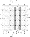
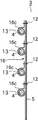
法面保護材3は、図1〜3に示すように、河川遮水シート5を有しており、河川遮水シート5には、錘保持部材として複数個の布型枠6が縫合または接着によって一体に取り付けられている。
As shown in FIGS. 1 to 3, the
各布型枠6は、直線状に形成された複数個(図1では、2個)の本体部6aが並設され、これらの本体部6aを連結する一対の連結部6bが本体部6aの両端にそれぞれ直角に連設されたI字並列形のものである。ここで、I字並列形とは、1個以上のI字を平行に並べた形状を意味する。
Each
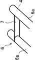
また、各布型枠6には、図1および図4に示すように、可倒性を備えた布製の覆土すべり止めシート7が複数枚、それぞれ本体部6a間に架け渡される形で本体部6aに90°で交差する方向に沿って垂れ幕状に取り付けられている。この覆土すべり止めシート7の取付手法としては、ロープ懸垂方式が採用されている。すなわち、布型枠6にロープ通し部材(図示せず)が取り付けられており、覆土すべり止めシート7の上辺にロープ(図示せず)が挿通され、このロープが布型枠6のロープ通し部材に通され、所定の緊結力(締め加減)で緊結されている。
In addition, as shown in FIGS. 1 and 4, each
さらに、各布型枠6には錘注入口(図示せず)が設けられている。
Furthermore, each
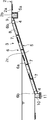
法面保護材3は以上のような構成を有するので、図2に示すように、この法面保護材3を用いて堤防2の法面保護作業を行う際には、次の手順による。
Since the
まず、資材搬入工程において、必要個数の法面保護材3を現場、つまり堤防2の近くに搬入する。このとき、法面保護材3は、その布型枠6が空であるとともに、覆土すべり止めシート7が可倒性を備えているため、軽量で嵩張らない。その結果、資材の搬送費用を低廉に抑えることができる。
First, in the material carrying-in process, a necessary number of
次に、載荷工程に移行し、法面保護材3の各布型枠6内に、錘として現場の土を注入する。すると、布型枠6の本体部6aおよび連結部6bの内部に現場の土が供給されて充填されるため、布型枠6が膨張する。さらに、この布型枠6の膨張に伴い、覆土すべり止めシート7が持ち上がって緊張状態となる。したがって、作業者が覆土すべり止めシート7を緊張させる手間はない。
Next, it transfers to a loading process and in-situ soil is inject | poured in each
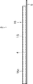
次いで、図2に示すように、敷設工程に移行し、堤防2の表法面2cに法面保護材3をその布型枠6の本体部6aが表法面2cの傾斜方向(図1上下方向)に合致するように敷設する。そして、法面保護材3の河川遮水シート5の上端部5aを堤防2の天端2aに固着することにより、法面保護材3を堤防2の表法面2cに固定する。河川遮水シート5の上端部5aを堤防2の天端2aに固着するには、堤防2の天端2aに予めアンカー埋設穴2bを穿設しておき、河川遮水シート5の上端部5aをこのアンカー埋設穴2bに載置した状態で、コンクリートブロックや石材などのアンカー9をアンカー埋設穴2bに落とし込むことにより、河川遮水シート5の上端部5aをアンカー9の周囲に回り込ませるようにしてアンカー9と堤防2の地山とで挟持すればよい。
Next, as shown in FIG. 2, the process proceeds to the laying process, and the
このとき、布型枠6の本体部6aのみならず連結部6bの内部にも土が充填されているので、布型枠6は堤防2の表法面2c上で安定し、位置決めが容易となる。また、布型枠6においては、複数枚の覆土すべり止めシート7が本体部6a間に所定の緊結力で架け渡されているので、布型枠6の蛇行を阻止することができる。
At this time, since not only the
最後に、堤防2の表法面2cの景観を改善するため、覆土工程に移行し、土砂などの覆土材8で法面保護材3を覆う。このとき、布型枠6の覆土すべり止めシート7が覆土材8の滑落を防ぐため、覆土材8は安定する。
Finally, in order to improve the landscape of the
ここで、法面保護材3による法面保護作業が終了する。
Here, the slope protection work by the
このように、この法面保護材3による法面保護作業では、現場の土が錘として有効活用されるため、重量のある錘を現場まで搬送する必要がない。この点からも、資材の搬送費用を低廉に抑えることができる。
Thus, in the slope protection work by the
また、河川遮水シート5と錘を別々に2工程で敷設する必要はなく、法面保護材3を堤防2の表法面2cに敷設する1工程で済むため、施工手間を省くことができる。
In addition, it is not necessary to separately lay the river water-
しかも、布型枠6は河川遮水シート5に一体に設けられているので、たとえ堤防2の表法面2cの勾配がきつくても、布型枠6が表法面2cの傾斜方向に滑落する恐れはない。したがって、河川遮水シート5が流失する事態を確実に阻止することができる。
In addition, since the
なお、上述の実施形態においては、錘として現場の土を用いた場合について説明したが、モルタルやコンクリートを代用することも可能である。コンクリートを錘として用いる場合、布型枠6の本体部6aのみならず連結部6bにまでコンクリートを行き渡らせるには、布型枠6の内径をある程度大きくする必要がある。これに対し、モルタルを錘として用いる場合は、モルタルの流動性の良好さにより、布型枠6の内径を小さくすることができる。また、砂とセメントを撹拌したものを錘として使用することもできる。この場合、これを粉体の状態で布型枠6内に圧入した後、散水によって固化させればよい。さらに、暫定施工の場合には、土砂、石材、コンクリート殻を詰めるようにしても構わない。
In addition, in the above-mentioned embodiment, although the case where the soil of the field was used as a weight was demonstrated, mortar and concrete can be substituted. When using concrete as a weight, in order to spread concrete not only to the
また、上述の実施形態においては、河川遮水シート5に布型枠6を取り付けただけ法面保護材3について説明したが、不織布などクッション性のある吸出防止シート(図示せず)や補強マット(図示せず)を河川遮水シート5の片面または両面に貼設し、これに布型枠6を取り付けて法面保護材3を構成してもよい。
Moreover, in the above-mentioned embodiment, although the
また、上述の実施形態においては、布製の覆土すべり止めシート7を用いた場合について説明したが、覆土すべり止めシート7の材質としては、布以外のもの種々考えられる。例えば、細めの間伐材を並べ、ロープを通して板状に一体化したものを採用してもよい。また、金網(菱形の金網、溶接金網、エキスパンドメタルなど)に吸出防止シートを敷設したものを採用しても構わない。さらに、再生プラスチック板、コンクリート板、スレート板を使用することもできる。
In the above-described embodiment, the case where the cloth-covered
また、上述の実施形態においては、錘保持部材として布型枠6を用いた場合について説明したが、布型枠6以外の錘保持部材を採用することも可能である。
In the above-described embodiment, the case where the
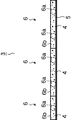
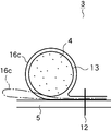
例えば、図5〜7に示すように、直線状に形成された織布またはネットからなる複数個(図6では、4個)のパイプ挿通部16cが並設され、各パイプ挿通部16cにそれぞれ、所定の内径(例えば、10cm)の円筒状に形成された塩化ビニル製のパイプ13が挿通された錘保持管16を錘保持部材として用い、図8に示すように、縫合糸や金具などの固着具12で錘保持管16の各パイプ挿通部16cを河川遮水シート5に取り付けることもできる。
For example, as shown in FIGS. 5 to 7, a plurality of (four in FIG. 6)
この錘保持管16を備えた法面保護材3を用いて堤防2の法面保護作業を行う際には、次の手順による。
When the slope protection work of the
まず、資材搬入工程において、必要個数の法面保護材3を現場、つまり堤防2の近くに搬入する。このとき、法面保護材3は、その錘保持管16が空であり、軽量であるため、資材の搬送費用を低廉に抑えることができる。
First, in the material carrying-in process, a necessary number of
次に、載荷工程に移行し、法面保護材3の各パイプ13内に、錘としてコンクリートを注入する。すると、パイプ13の内部にコンクリートが供給されて充填される。この状態で、所定の時間だけ養生してコンクリートをパイプ13内で硬化させる。
Next, it transfers to a loading process and concrete is inject | poured in each
次いで、図2に示すように、敷設工程に移行し、堤防2の表法面2cに法面保護材3をその錘保持管16のパイプ挿通部16cが表法面2cの傾斜方向(図5上下方向)に直交するように敷設する。そして、上述の実施形態と同様の手順で、法面保護材3の河川遮水シート5の上端部5aを堤防2の天端2aに固着することにより、法面保護材3を堤防2の表法面2cに固定する。
Next, as shown in FIG. 2, the process proceeds to a laying process, where the
最後に、堤防2の表法面2cの景観を改善するため、覆土工程に移行し、土砂などの覆土材8で法面保護材3を覆う。このとき、法面保護材3の錘保持管16が覆土材8の滑落を防ぐため、覆土材8は安定する。
Finally, in order to improve the landscape of the
ここで、法面保護材3による法面保護作業が終了する。
Here, the slope protection work by the
このように、この法面保護材3による法面保護作業では、河川遮水シート5と錘を別々に2工程で敷設する必要はなく、法面保護材3を堤防2の表法面2cに敷設する1工程で済むため、施工手間を省くことができる。
Thus, in the slope protection work by the
また、錘保持管16は河川遮水シート5に一体に設けられているので、たとえ堤防2の表法面2cの勾配がきつくても、錘保持管16が表法面2cの傾斜方向に滑落する恐れはない。したがって、河川遮水シート5が流失する事態を確実に阻止することができる。
Further, since the
2……堤防
2c……表法面
3……法面保護材
5……河川遮水シート
6……布型枠(錘保持部材)
6a……本体部
6b……連結部
7……覆土すべり止めシート
8……覆土材
13……パイプ
16……錘保持管(錘保持部材)
16c……パイプ挿通部
2 ……
6a ……
16c …… Pipe insertion part
Claims (9)
直線状に形成された複数個の本体部が並設され、これらの本体部を連結する一対の連結部が当該本体部の両端にそれぞれ直角に連設された布型枠であることを特徴とする請求項1に記載の法面保護材。 The weight holding member is
A plurality of body parts formed in a straight line are arranged side by side, and a pair of connecting parts that connect these body parts are cloth mold frames that are connected to both ends of the body part at right angles. The slope protection material according to claim 1.
直線状に形成された複数個のパイプ挿通部が並設され、前記各パイプ挿通部にそれぞれパイプが挿通された錘保持管であることを特徴とする請求項1に記載の法面保護材。 The weight holding member is
2. The slope protection material according to claim 1, wherein the slope protection material is a weight holding tube in which a plurality of pipe insertion portions formed in a straight line are juxtaposed, and pipes are respectively inserted into the pipe insertion portions.
前記法面保護材の錘保持部材に錘を載せる載荷工程と、
堤防の表法面に前記法面保護材を敷設して固定する敷設工程と、
前記法面保護材を覆土材で覆う覆土工程と
を含むことを特徴とする法面保護工法。 A slope protection method using the slope protection material according to claim 1,
A loading step of placing a weight on the weight holding member of the slope protection material;
Laying step of laying and fixing the slope protection material on the surface of the dike,
A slope covering process for covering the slope protective material with a soil covering material.
前記法面保護材の布型枠に錘を充填する載荷工程と、
堤防の表法面に前記法面保護材をその布型枠の本体部が当該表法面の傾斜方向に合致するように敷設して固定する敷設工程と、
前記法面保護材を覆土材で覆う覆土工程と
を含むことを特徴とする法面保護工法。 A slope protection method using the slope protection material according to any one of claims 2 to 5,
A loading step of filling weights in the cloth form of the slope protection material;
A laying step of laying and fixing the slope protection material on the surface of the dike so that the main body portion of the cloth form frame matches the inclination direction of the surface slope;
A slope covering process for covering the slope protective material with a soil covering material.
前記法面保護材の錘保持部材のパイプに錘を充填する載荷工程と、
堤防の表法面に前記法面保護材をその錘保持部材のパイプ挿通部が当該表法面の傾斜方向に交差するように敷設して固定する敷設工程と、
前記法面保護材を覆土材で覆う覆土工程と
を含むことを特徴とする法面保護工法。
A slope protection method using the slope protection material according to claim 6,
A loading step of filling the pipe of the weight holding member of the slope protection material with a weight;
A laying step of laying and fixing the slope protection material on the surface of the dike so that the pipe insertion portion of the weight holding member intersects the inclination direction of the surface slope;
A slope covering process for covering the slope protective material with a soil covering material.
Priority Applications (1)
| Application Number | Priority Date | Filing Date | Title |
|---|---|---|---|
| JP2004107454A JP2005290840A (en) | 2004-03-31 | 2004-03-31 | Slope protecting material and slope protecting method |
Applications Claiming Priority (1)
| Application Number | Priority Date | Filing Date | Title |
|---|---|---|---|
| JP2004107454A JP2005290840A (en) | 2004-03-31 | 2004-03-31 | Slope protecting material and slope protecting method |
Publications (1)
| Publication Number | Publication Date |
|---|---|
| JP2005290840A true JP2005290840A (en) | 2005-10-20 |
Family
ID=35324086
Family Applications (1)
| Application Number | Title | Priority Date | Filing Date |
|---|---|---|---|
| JP2004107454A Pending JP2005290840A (en) | 2004-03-31 | 2004-03-31 | Slope protecting material and slope protecting method |
Country Status (1)
| Country | Link |
|---|---|
| JP (1) | JP2005290840A (en) |
Cited By (2)
| Publication number | Priority date | Publication date | Assignee | Title |
|---|---|---|---|---|
| CN111236151A (en) * | 2020-01-14 | 2020-06-05 | 沧州昊海水利工程质量检测有限公司 | River course slope protection laying construction method for hydraulic engineering |
| CN118326900A (en) * | 2024-05-09 | 2024-07-12 | 广东广建建工集团有限公司 | A river bank protection paving construction method for water conservancy projects |
Citations (4)
| Publication number | Priority date | Publication date | Assignee | Title |
|---|---|---|---|---|
| JPS645925U (en) * | 1987-06-24 | 1989-01-13 | ||
| JPH1082031A (en) * | 1996-09-09 | 1998-03-31 | Asahi Chem Ind Co Ltd | Cloth form with borrow-material receiving section |
| JP2000154519A (en) * | 1998-11-19 | 2000-06-06 | Asahi Chem Ind Co Ltd | Planting and protecting bank material |
| JP2003278128A (en) * | 2002-03-25 | 2003-10-02 | Takuo Yukimoto | Protection mat for surface of slope of river and civil engineering structure by use of the same |
-
2004
- 2004-03-31 JP JP2004107454A patent/JP2005290840A/en active Pending
Patent Citations (4)
| Publication number | Priority date | Publication date | Assignee | Title |
|---|---|---|---|---|
| JPS645925U (en) * | 1987-06-24 | 1989-01-13 | ||
| JPH1082031A (en) * | 1996-09-09 | 1998-03-31 | Asahi Chem Ind Co Ltd | Cloth form with borrow-material receiving section |
| JP2000154519A (en) * | 1998-11-19 | 2000-06-06 | Asahi Chem Ind Co Ltd | Planting and protecting bank material |
| JP2003278128A (en) * | 2002-03-25 | 2003-10-02 | Takuo Yukimoto | Protection mat for surface of slope of river and civil engineering structure by use of the same |
Cited By (2)
| Publication number | Priority date | Publication date | Assignee | Title |
|---|---|---|---|---|
| CN111236151A (en) * | 2020-01-14 | 2020-06-05 | 沧州昊海水利工程质量检测有限公司 | River course slope protection laying construction method for hydraulic engineering |
| CN118326900A (en) * | 2024-05-09 | 2024-07-12 | 广东广建建工集团有限公司 | A river bank protection paving construction method for water conservancy projects |
Similar Documents
| Publication | Publication Date | Title |
|---|---|---|
| JPH07300820A (en) | Adhesive protection net construction method for falling rocks and its rope / net anchor structure | |
| KR101845199B1 (en) | Restoration method for relocation and topography of building site remained | |
| KR101832891B1 (en) | Fixing and placing method of a foundation layer in water by geotextile with pre-attached armourstone mattress bag and roll structure | |
| JP2005290840A (en) | Slope protecting material and slope protecting method | |
| JP5186315B2 (en) | Anticorrosion lining method for column members | |
| JP5100513B2 (en) | Reinforced earth wall and its construction method | |
| JPH0849237A (en) | Slope face covering structure and mat | |
| TWI558887B (en) | Construction methods and filling methods for weak sites and sites with liquefaction concerns, as well as structural bags | |
| KR101339571B1 (en) | Steel jointing structure | |
| JP4364063B2 (en) | Construction method of earth retaining bag and retaining wall | |
| JP2001040629A (en) | Sandbag for form in civil engineering work and civil engineering work using it | |
| JP3650050B2 (en) | Construction stone for civil engineering structures | |
| JP3621362B2 (en) | Construction stone for civil engineering structures | |
| JP4488724B2 (en) | Protective structure of internal pressure buried pipe deformation site | |
| JPH05214703A (en) | Method of constructing structure by foamed resin block | |
| KR101829192B1 (en) | Building foundation method using wedge type shu | |
| JP2007218077A (en) | Sheet member for restraining and reinforcing material | |
| KR101674865B1 (en) | Shotcrete retaining wall and construction method thereof | |
| JPH011828A (en) | Top-shaped block for ground stabilization and its installation method | |
| JPH04254614A (en) | Reinforcement for banking | |
| JPH05306523A (en) | Banking work | |
| JPS6347418A (en) | Reinforcing structure of banking ground | |
| JP3502895B2 (en) | Landfill method | |
| KR101499421B1 (en) | safety embankment raising the ground level construction method | |
| JP2002061148A (en) | Asphalt mat and underwater impermeable method |
Legal Events
| Date | Code | Title | Description |
|---|---|---|---|
| A131 | Notification of reasons for refusal |
Free format text: JAPANESE INTERMEDIATE CODE: A131 Effective date: 20060620 |
|
| A02 | Decision of refusal |
Free format text: JAPANESE INTERMEDIATE CODE: A02 Effective date: 20061017 |