JP2005290771A - Joint material for frame material assembly - Google Patents
Joint material for frame material assembly Download PDFInfo
- Publication number
- JP2005290771A JP2005290771A JP2004105704A JP2004105704A JP2005290771A JP 2005290771 A JP2005290771 A JP 2005290771A JP 2004105704 A JP2004105704 A JP 2004105704A JP 2004105704 A JP2004105704 A JP 2004105704A JP 2005290771 A JP2005290771 A JP 2005290771A
- Authority
- JP
- Japan
- Prior art keywords
- hole
- joint member
- bolt
- groove
- prism
- Prior art date
- Legal status (The legal status is an assumption and is not a legal conclusion. Google has not performed a legal analysis and makes no representation as to the accuracy of the status listed.)
- Granted
Links
- 239000000463 material Substances 0.000 title claims description 9
- 230000037431 insertion Effects 0.000 claims abstract description 20
- 238000003780 insertion Methods 0.000 claims abstract description 20
- 230000000149 penetrating effect Effects 0.000 claims abstract description 4
- 239000000428 dust Substances 0.000 abstract description 3
- 230000000694 effects Effects 0.000 description 2
Images
Landscapes
- Joining Of Building Structures In Genera (AREA)
Abstract
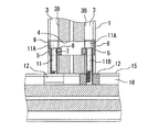
【課題】対応する少なくとも二面に長手方向に伸びる溝を有し、かつ前記二面に渉って貫通された貫通孔4を備えた角柱1と、他の角柱15を連結する場合において、該貫通孔4にボルトを備えたジョイント部材を挿通し、これによって二角柱を連結するが、従来のジョイント部材では貫通孔の開口部を塞ぐ構造にはなっていないので、貫通孔に塵埃等が入り、かつ美観を損ねるところがあった。
【解決手段】本発明のジョイント部材5は、角柱に設けた貫通孔4に挿入されるジョイント部材5であって、貫通孔4の開口に適合する形状を有する閉鎖部6と、閉鎖部6の背部に一体的に設けた、ボルト挿通孔7を有するボルト支持部8と、閉鎖部6の上部に突出した角柱の溝3に係合する幅を有する溝係合部9とからなり、ボルト挿通孔7にはボルト11が挿入されてなる。
【選択図】
図14
In connecting a prism 1 having a groove extending in the longitudinal direction on at least two corresponding surfaces and having a through hole 4 penetrating through the two surfaces, and another prism 15 are connected, A joint member having a bolt is inserted into the through hole 4 to connect the square pillar, but the conventional joint member is not structured to close the opening of the through hole, so dust or the like enters the through hole. And there was a place that detracted from aesthetics.
A joint member 5 of the present invention is a joint member 5 inserted into a through hole 4 provided in a prism, and has a closing portion 6 having a shape that fits the opening of the through hole 4, and the closing portion 6 A bolt support portion 8 having a bolt insertion hole 7 provided integrally with a back portion, and a groove engaging portion 9 having a width for engaging with a prismatic groove 3 projecting from the upper portion of the closing portion 6. Bolts 11 are inserted into the holes 7.
[Selection]
FIG.
Description
本発明は、軸方向に溝を有する柱状の枠部材を、複数本使用して立体的構造物に組み立てる場合において、枠部材同士の連結に使用するためのジョイント部材に関する。 The present invention relates to a joint member used for connecting frame members when a plurality of columnar frame members having grooves in the axial direction are used to assemble a three-dimensional structure.
四角柱の各面に長手方向に伸びる溝を有する枠部材を、複数本組み合わせて各種機器を取付ける基台等の構造物を組み立てることがある。特に、一本の枠部材の中間側面に対して、他の枠部材の端面を当接して、T字状態で接続するような場合、他方の枠部材に一側から対抗する一側へ貫通する孔を穿ち、この孔に一本のジョイント部材を挿通し、このジョイントの先端と後端とに設けた切欠きに夫々ボルトを挿通し、両ボルトの先端部を、一方の枠部材の溝中に臨ませ、溝中でナットに螺合することによって、二本の枠部材をT字状に接続している。
特開2000−64437号公報に開示されたジョイント部材には切欠きが不可欠であるが、切欠きがあるために、粉塵、油等がボルト等が頭部およびその周辺に付着し易く、また、ジョイント部材の挿入個所は切欠きがあるため窪んで見え、見映えが悪いなどの問題があった。
本発明では、枠部材に穿った貫通孔の開口を塞ぐようにして装着できる、ボルトを担持した状態で用いるジョイント部材を提供することによって、従来の問題点を回避しようとするものである。
The joint member disclosed in Japanese Patent Application Laid-Open No. 2000-64437 requires a notch, but because there is a notch, dust, oil, etc. are likely to adhere to the head and its surroundings. The insertion part of the joint member has a problem such as a notch due to a notch and poor appearance.
In the present invention, the conventional problem is to be avoided by providing a joint member used in a state where a bolt is supported, which can be installed so as to close the opening of the through hole formed in the frame member.
請求項1に記載した発明は、対応する少なくとも二面に長手方向に伸びる溝を有し、かつ前記二面に渉って貫通された貫通孔を備えた角柱において、前記貫通孔に挿入されるジョイント部材であって、該ジョイント部材は、前記貫通孔の開口に適合する形状を有する閉鎖部と、前記閉鎖部の背部に一体的に設けた、ボルト挿通孔を有するボルト支持部と、前記閉鎖部の上部に突出した前記角柱の溝に係合する幅を有する溝係合部とからなり、前記ボルト挿通孔にはボルトを挿入してなることを特徴とする枠材組立用ジョイント部材である。
The invention described in
上記構成によって、ボルトを担持したジョイント部材は、溝係合部を角柱に設けた溝に整合することによって位置決めされながら、角柱に穿たれた貫通孔に挿入され、閉鎖部が角柱の表面と面一になった状態で、取付けたボルトの軸部は角柱の溝中にあって、その先端は他の角柱の溝部に臨むようになるので、他の角柱と容易に連結することができ、また、貫通孔の開口部は閉鎖部によって塞ぐことになる。 With the above configuration, the joint member carrying the bolt is inserted into the through-hole drilled in the prism while being positioned by aligning the groove engaging portion with the groove provided in the prism, and the closing portion is the surface and surface of the prism. In the same state, the shaft of the installed bolt is in the groove of the prism, and its tip comes to face the groove of the other prism, so it can be easily connected to other prisms, and The opening of the through hole is closed by the closing part.
請求項2に記載した発明は、請求項1に記載した枠材組立用ジョイント部材おいて、前記ボルト支持部に対抗する位置に、前記ボルト孔を共通に有する第2のボルト支持部を設け、必要に応じて、前記閉鎖部にはその下部に突出する第2の溝係合部を設けたことを特徴とする枠材組立用ジョイント部材である。
The invention described in
請求項1に記載した発明の特徴のほかに、第2のボルト支持部を設けることによって、ジョイント部材を上下いずれの方向にしても貫通孔に取付けられるので、取り扱いにおける方向性がなくなる。
In addition to the features of the invention described in
請求項3に記載した発明は、請求項1または請求項2に記載した枠材組立用ジョイント部材おいて、前記ボルトを前記ボルト挿通孔に挿通した状態で、前記ジョイント部材を前記貫通孔に挿入し、前記閉鎖部が前記貫通孔の開口部に嵌合したとき、ボルト頭部は、角柱に設けた長手方向の溝の底部に衝合するように設けたことを特徴とする枠材組立用ジョイント部材である。 According to a third aspect of the present invention, in the frame material assembly joint member according to the first or second aspect, the joint member is inserted into the through hole in a state where the bolt is inserted into the bolt insertion hole. And when the closing portion is fitted into the opening of the through hole, the bolt head is provided so as to abut against the bottom of the longitudinal groove provided in the prism. It is a joint member.
請求項1または請求項2に記載した発明の特徴のほかに、ジョイント部材の貫通孔への挿入深さの度合いをボルトの頭部と溝の底部との衝合によって、決めることができる。
In addition to the features of the invention described in
請求項1に記載の本発明は、角柱の貫通孔に、ボルトと共にジョイント部材を挿入すると、ジョイント部材の閉鎖部によって、貫通孔の開口を塞ぐことになり、閉鎖部の背面に、貫通孔の殆どとボルトの頭部が位置しているので、貫通孔への粉塵等が入ることを防止でき、角柱の表面と閉鎖部の表面とが面一となって、見た目を良くした状態で締結部を隠すことができる。 According to the first aspect of the present invention, when the joint member is inserted together with the bolt into the through hole of the prism, the opening of the through hole is closed by the closing part of the joint member. Most of the bolt heads are located, so it is possible to prevent dust and the like from entering the through-holes, and the surface of the prism and the surface of the closing part are flush with each other and the fastening part is in a good appearance Can be hidden.
請求項2に記載の本発明は、上記効果のほかに、ジョイント部材に二のボルト支持部を対抗する位置に設け、両ボルト支持部を貫通するようにボルト孔が位置しているので、ボルトを何れの方からでも挿入できるので、作業を正確迅速に行うことができる。
In addition to the above-described effect, the present invention as set forth in
請求項3に記載の本発明は、上記効果のほかに、ジョイント部材の貫通孔への挿入深さをボルトの頭部と角柱の溝底部との衝合を利用して行うようにしたので、ジョイント部材とボルトを組み合わせた状態で、自動的に貫通孔への挿入深度を一定とすることができ、作業の単純化、迅速化が期待できる。 According to the third aspect of the present invention, in addition to the above-described effect, the insertion depth of the joint member into the through hole is performed using an abutment between the head of the bolt and the groove bottom of the prism. In a state where the joint member and the bolt are combined, the depth of insertion into the through hole can be automatically made constant, and simplification and speeding up of the operation can be expected.
本発明は、図1乃至図5並びに図13乃至図15に示すように、枠材である角柱を、例えば、T字状に接続するために用いる枠材組立用ジョイント部材である。 As shown in FIGS. 1 to 5 and FIGS. 13 to 15, the present invention is a frame material assembling joint member used to connect a rectangular column as a frame material, for example, in a T shape.
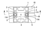
角柱1は、対応する少なくとも二面2,2に長手方向に伸びる溝3,3を有し、かつ前記二面に渉って貫通された貫通孔4を備えている。
角柱に設けられた溝3は、開口3Aより底部3B側が広くなっている。また、貫通孔4の断面形状は円形,多角形いずれでも良いが,望ましくは円形が望ましい。
The
The
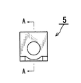
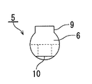
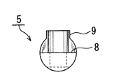
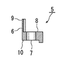
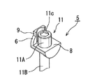
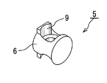
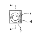
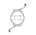
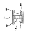
貫通孔4に挿入されるジョイント部材5は、貫通孔4の開口4Aに適合する形状を有する閉鎖部6と、閉鎖部6の背部に一体的に設けた、ボルト挿通孔7を有するボルト支持部8と、閉鎖部6の上部に突出した角柱1の溝3の開口3Aに係合する幅を有する溝係合部9とからなる。ボルト挿通孔7と溝係合部9とは、同一方向を向くことになる。
ジョイント部材5の閉鎖部6の正面視形状は、貫通孔4の開口に適合するため貫通孔4の開口4Aの形状による。貫通孔4の開口4Aの形状が円形ならば、閉鎖部6も円形となる。ボルト支持部8の上面は、ボルトを安定して支持させるため平坦であるが、その下面は貫通孔4の内面に沿うため,図面で示すものは部分的に円弧面を有する。閉鎖部の上部に突出した溝係合部9は,ジョイント部材の挿入時の位置決めと回転止め並びに溝3の開口閉鎖の機能を有し、その横幅は、溝3の開口3Aの幅にほぼ等しい。
The
The front view shape of the
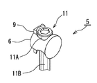
ジョイント部材5を貫通孔4に対し,表裏から夫々対抗して挿入するに際し、ジョイント部材5のボルト挿通孔7にはボルト11を挿入し、ボルト頭部11Aをボルト支持部8に係止し、ボルト軸部11Bを角柱1の溝3の長手方向に沿うようにしてジョイント部材5を夫々貫通孔4に挿入する。このとき、ジョイント部材5の閉鎖部6の表面と、角柱1の側面と面一となるようにして挿入されると共にジョイント部材5の閉鎖部6の周縁は貫通孔4の開口4Aに嵌合し、溝係合部9は溝3の開口部3Aに嵌合する。この状態で貫通孔の開口は閉鎖状態になる。ボルト頭部11Aの頂面には工具係合凹部11Cが形成されている。
When inserting the
そして、各ボルト11の先端は、他の角柱15の溝16に臨ませ、溝16に係合したナット12に夫々ねじ込むことによって、二本の角柱1、16は二箇所において固定され、一体に連結される。このような枠材の連結を組み合わせつつ立体的構造物を構築してゆくことができる。
Then, the tip of each
また、ジョイント部材5の溝係合部9の上面およびボルト支持部8の下面に形成された平面10は、角柱の溝3の開口に嵌込む帯状シール部材の端面(長手方向に対して直交する平面となっている)が当接した際に隙間なくフィットするために形成されている。
Further, the
また、ジョイント部材5の貫通孔4への挿入深さの度合いをボルト頭部11Aと、溝
13の底部13Aとの衝合によって決めるようにすることができる。ボルト11をボルト挿通孔7に挿通した状態で、ジョイント部材5を貫通孔4に挿入し、閉鎖部6が貫通孔4の開口部に嵌合したとき、ボルト頭部11Aが、角柱に設けた長手方向の溝3の底部3Aに衝合するように設けることによって、ジョイント部材5を単に押し込むだけで、その停止位置が所定位置に達したものとすることができるので、作業の迅速性を図ることができる。
Further, the degree of insertion depth of the
実施例を,図8乃至図12に基づいて説明する。
なお、この実施例において、先の最良の形態で示した部材または部分と同一または類似のものについては,同一の番号を付し詳細な説明を省略する。
An embodiment will be described with reference to FIGS.
In this embodiment, the same or similar members or parts as those shown in the best mode are given the same reference numerals and detailed explanations are omitted.
図1乃至図5で示したジョイント部材5は、垂直に保持した角柱1に対し使用する場合、ボルト支持部8を上方に向けて貫通孔4に挿入する必要があった。
図8乃至図11に示す実施例においては、ジョイント部材5を、上下いずれの向きにしても使用できるように構成としたものである。
When the
In the embodiment shown in FIGS. 8 to 11, the
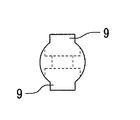
すなわち、ジョイント部材1は、貫通孔の開口に適合する形状を有する閉鎖部6と、閉鎖部6の背部に一体的に設けた、一対のボルト支持部8、8Aと、一対のボルト支持部を貫通するボルト挿通孔7と、閉鎖部6の上部および下部に突出し、ボトル挿通孔7と並行に伸びた、角柱の溝に係合する幅を有する一対の溝係合部9、9Aとからなる。一対の溝係合部9、9Aは一方を省略することができる。
ジョイント部材1は、一つのボルト支持部8に対抗する位置に、ボルト挿通孔7を共通に有する第2のボルト支持部8Aを設けたものであるから、ボルトを上下いずれの側からでもボルト挿通孔7へ挿通可能となるので、ジョイント部材1を一方の溝係合部9を溝に係合すうようにボルトと共に貫通孔4に嵌込めば良いので、より作業が迅速になる。
That is, the
Since the
1 角柱
2 角柱の側面
3 角柱に設けた溝
3A 溝の開口
3B 溝の底部
4 貫通孔
4A 貫通孔の開口
5 ジョイント部材
6 ジョイント部材の閉鎖部
7 ジョイント部材のボルト挿通孔
8、8A ジョイント部材のボルト支持部
9、9A ジョイント部材の溝係合部
10 平面
11 ボルト
12 ナット
15 他の角柱
16 他の角柱の溝
DESCRIPTION OF
Claims (3)
The joint member for frame material assembly according to claim 1 or 2, wherein the joint member is inserted into the through hole in a state where the bolt is inserted into the bolt insertion hole, and the closing portion is the through hole. A frame material assembling joint member, wherein the bolt head portion is provided so as to abut against a bottom portion of a longitudinal groove provided in the prism.
Priority Applications (1)
| Application Number | Priority Date | Filing Date | Title |
|---|---|---|---|
| JP2004105704A JP4512867B2 (en) | 2004-03-31 | 2004-03-31 | Joint material for frame material assembly |
Applications Claiming Priority (1)
| Application Number | Priority Date | Filing Date | Title |
|---|---|---|---|
| JP2004105704A JP4512867B2 (en) | 2004-03-31 | 2004-03-31 | Joint material for frame material assembly |
Publications (2)
| Publication Number | Publication Date |
|---|---|
| JP2005290771A true JP2005290771A (en) | 2005-10-20 |
| JP4512867B2 JP4512867B2 (en) | 2010-07-28 |
Family
ID=35324020
Family Applications (1)
| Application Number | Title | Priority Date | Filing Date |
|---|---|---|---|
| JP2004105704A Expired - Lifetime JP4512867B2 (en) | 2004-03-31 | 2004-03-31 | Joint material for frame material assembly |
Country Status (1)
| Country | Link |
|---|---|
| JP (1) | JP4512867B2 (en) |
Citations (3)
| Publication number | Priority date | Publication date | Assignee | Title |
|---|---|---|---|---|
| JPS53122245U (en) * | 1977-03-03 | 1978-09-28 | ||
| JPH05118307A (en) * | 1990-05-21 | 1993-05-14 | Wolfgang Rixen | Side connecting section of molding rod |
| JPH0726636A (en) * | 1993-07-07 | 1995-01-27 | Smc Corp | Connection mechanism of structure member |
-
2004
- 2004-03-31 JP JP2004105704A patent/JP4512867B2/en not_active Expired - Lifetime
Patent Citations (3)
| Publication number | Priority date | Publication date | Assignee | Title |
|---|---|---|---|---|
| JPS53122245U (en) * | 1977-03-03 | 1978-09-28 | ||
| JPH05118307A (en) * | 1990-05-21 | 1993-05-14 | Wolfgang Rixen | Side connecting section of molding rod |
| JPH0726636A (en) * | 1993-07-07 | 1995-01-27 | Smc Corp | Connection mechanism of structure member |
Also Published As
| Publication number | Publication date |
|---|---|
| JP4512867B2 (en) | 2010-07-28 |
Similar Documents
| Publication | Publication Date | Title |
|---|---|---|
| JP5111058B2 (en) | Bonding structure of structural materials | |
| EP3325821B1 (en) | Clip lock fasteners and fastening system | |
| JP4512867B2 (en) | Joint material for frame material assembly | |
| JP4502677B2 (en) | Metal fittings for wooden construction | |
| JP4936470B2 (en) | Metal column and beam connection bracket | |
| JP2002250327A (en) | Connection bracket | |
| JP4128148B2 (en) | Wall panel | |
| JP3133662U (en) | Partition plate fixture | |
| JP3403370B2 (en) | Fastening member for building board, building board to which the fastening member is fixed, and fastening structure thereof | |
| JP4111449B2 (en) | Fence body | |
| JPH0119693Y2 (en) | ||
| JP3137149U (en) | Columnar member shaft structure and shaft assembly | |
| JP4060280B2 (en) | Joint structure of wood structure members | |
| JP2744589B2 (en) | Plate mounting device | |
| JP2001227070A (en) | Splicing hardware for joint | |
| JP4468038B2 (en) | Metal fittings for wooden construction | |
| JP2012077436A (en) | Connection method for closed section members | |
| JPH0342249Y2 (en) | ||
| JP2526218Y2 (en) | Connecting device for partition panel | |
| JP2006171097A (en) | Frame device | |
| JPH11200490A (en) | Joint of wooden building and connecting structure using the same | |
| JP3020047B2 (en) | Joint structure of frame member and frame body provided with the same | |
| JPH071371Y2 (en) | Cross rail structure in partition device | |
| JP2000139738A (en) | Structure for mounting counter to cabinet | |
| JPH0631216Y2 (en) | Structural member having a closed cross-sectional shape |
Legal Events
| Date | Code | Title | Description |
|---|---|---|---|
| A521 | Request for written amendment filed |
Free format text: JAPANESE INTERMEDIATE CODE: A523 Effective date: 20050728 |
|
| A621 | Written request for application examination |
Free format text: JAPANESE INTERMEDIATE CODE: A621 Effective date: 20070327 |
|
| A977 | Report on retrieval |
Free format text: JAPANESE INTERMEDIATE CODE: A971007 Effective date: 20081209 |
|
| A131 | Notification of reasons for refusal |
Free format text: JAPANESE INTERMEDIATE CODE: A131 Effective date: 20091209 |
|
| A521 | Request for written amendment filed |
Free format text: JAPANESE INTERMEDIATE CODE: A523 Effective date: 20091222 |
|
| A521 | Request for written amendment filed |
Free format text: JAPANESE INTERMEDIATE CODE: A523 Effective date: 20100119 |
|
| TRDD | Decision of grant or rejection written | ||
| A01 | Written decision to grant a patent or to grant a registration (utility model) |
Free format text: JAPANESE INTERMEDIATE CODE: A01 Effective date: 20100414 |
|
| A01 | Written decision to grant a patent or to grant a registration (utility model) |
Free format text: JAPANESE INTERMEDIATE CODE: A01 |
|
| A61 | First payment of annual fees (during grant procedure) |
Free format text: JAPANESE INTERMEDIATE CODE: A61 Effective date: 20100421 |
|
| R150 | Certificate of patent or registration of utility model |
Ref document number: 4512867 Country of ref document: JP Free format text: JAPANESE INTERMEDIATE CODE: R150 Free format text: JAPANESE INTERMEDIATE CODE: R150 |
|
| FPAY | Renewal fee payment (event date is renewal date of database) |
Free format text: PAYMENT UNTIL: 20130521 Year of fee payment: 3 |
|
| FPAY | Renewal fee payment (event date is renewal date of database) |
Free format text: PAYMENT UNTIL: 20130521 Year of fee payment: 3 |
|
| S531 | Written request for registration of change of domicile |
Free format text: JAPANESE INTERMEDIATE CODE: R313531 |
|
| FPAY | Renewal fee payment (event date is renewal date of database) |
Free format text: PAYMENT UNTIL: 20130521 Year of fee payment: 3 |
|
| R350 | Written notification of registration of transfer |
Free format text: JAPANESE INTERMEDIATE CODE: R350 |
|
| FPAY | Renewal fee payment (event date is renewal date of database) |
Free format text: PAYMENT UNTIL: 20130521 Year of fee payment: 3 |
|
| FPAY | Renewal fee payment (event date is renewal date of database) |
Free format text: PAYMENT UNTIL: 20140521 Year of fee payment: 4 |
|
| R250 | Receipt of annual fees |
Free format text: JAPANESE INTERMEDIATE CODE: R250 |
|
| R250 | Receipt of annual fees |
Free format text: JAPANESE INTERMEDIATE CODE: R250 |
|
| R250 | Receipt of annual fees |
Free format text: JAPANESE INTERMEDIATE CODE: R250 |
|
| R250 | Receipt of annual fees |
Free format text: JAPANESE INTERMEDIATE CODE: R250 |
|
| R250 | Receipt of annual fees |
Free format text: JAPANESE INTERMEDIATE CODE: R250 |
|
| R250 | Receipt of annual fees |
Free format text: JAPANESE INTERMEDIATE CODE: R250 |
|
| R250 | Receipt of annual fees |
Free format text: JAPANESE INTERMEDIATE CODE: R250 |
|
| R250 | Receipt of annual fees |
Free format text: JAPANESE INTERMEDIATE CODE: R250 |
|
| R250 | Receipt of annual fees |
Free format text: JAPANESE INTERMEDIATE CODE: R250 |
|
| R250 | Receipt of annual fees |
Free format text: JAPANESE INTERMEDIATE CODE: R250 |
|
| S531 | Written request for registration of change of domicile |
Free format text: JAPANESE INTERMEDIATE CODE: R313531 |
|
| R350 | Written notification of registration of transfer |
Free format text: JAPANESE INTERMEDIATE CODE: R350 |
|
| R250 | Receipt of annual fees |
Free format text: JAPANESE INTERMEDIATE CODE: R250 |
|
| EXPY | Cancellation because of completion of term |

