JP2005290719A - Contamination preventing apparatus - Google Patents
Contamination preventing apparatus Download PDFInfo
- Publication number
- JP2005290719A JP2005290719A JP2004104245A JP2004104245A JP2005290719A JP 2005290719 A JP2005290719 A JP 2005290719A JP 2004104245 A JP2004104245 A JP 2004104245A JP 2004104245 A JP2004104245 A JP 2004104245A JP 2005290719 A JP2005290719 A JP 2005290719A
- Authority
- JP
- Japan
- Prior art keywords
- float
- water
- weight
- pollution
- membrane
- Prior art date
- Legal status (The legal status is an assumption and is not a legal conclusion. Google has not performed a legal analysis and makes no representation as to the accuracy of the status listed.)
- Pending
Links
- 238000011109 contamination Methods 0.000 title claims abstract description 30
- XLYOFNOQVPJJNP-UHFFFAOYSA-N water Substances O XLYOFNOQVPJJNP-UHFFFAOYSA-N 0.000 claims abstract description 112
- 238000011144 upstream manufacturing Methods 0.000 claims abstract description 37
- 230000002265 prevention Effects 0.000 claims description 60
- 239000012528 membrane Substances 0.000 claims description 38
- 230000003373 anti-fouling effect Effects 0.000 claims description 5
- 238000000638 solvent extraction Methods 0.000 claims description 3
- 238000007599 discharging Methods 0.000 abstract description 6
- 230000015556 catabolic process Effects 0.000 abstract 1
- 238000006731 degradation reaction Methods 0.000 abstract 1
- 230000000630 rising effect Effects 0.000 description 5
- 230000002787 reinforcement Effects 0.000 description 3
- 230000003014 reinforcing effect Effects 0.000 description 3
- 239000004576 sand Substances 0.000 description 3
- 238000004062 sedimentation Methods 0.000 description 3
- 238000003756 stirring Methods 0.000 description 3
- 229920002430 Fibre-reinforced plastic Polymers 0.000 description 2
- 239000011151 fibre-reinforced plastic Substances 0.000 description 2
- 238000005192 partition Methods 0.000 description 2
- 229920000728 polyester Polymers 0.000 description 2
- 230000000717 retained effect Effects 0.000 description 2
- 238000009958 sewing Methods 0.000 description 2
- 239000002689 soil Substances 0.000 description 2
- 239000004593 Epoxy Substances 0.000 description 1
- 239000011248 coating agent Substances 0.000 description 1
- 238000000576 coating method Methods 0.000 description 1
- 238000004891 communication Methods 0.000 description 1
- 230000006866 deterioration Effects 0.000 description 1
- 230000000694 effects Effects 0.000 description 1
- 229920001971 elastomer Polymers 0.000 description 1
- 239000003344 environmental pollutant Substances 0.000 description 1
- 239000006260 foam Substances 0.000 description 1
- 238000009434 installation Methods 0.000 description 1
- 238000012423 maintenance Methods 0.000 description 1
- 238000004519 manufacturing process Methods 0.000 description 1
- 238000000034 method Methods 0.000 description 1
- 230000000704 physical effect Effects 0.000 description 1
- 231100000719 pollutant Toxicity 0.000 description 1
- 230000001737 promoting effect Effects 0.000 description 1
- 239000005060 rubber Substances 0.000 description 1
- 239000000126 substance Substances 0.000 description 1
- 229920003051 synthetic elastomer Polymers 0.000 description 1
- 239000005061 synthetic rubber Substances 0.000 description 1
Images
Landscapes
- Cleaning Or Clearing Of The Surface Of Open Water (AREA)
Abstract
Description
本発明は、ダム貯水池に貯えられている水の濁りを抑えることにより、放流時における汚濁水の流出を防止する汚濁防止装置に関する。 The present invention relates to a pollution control device that prevents the outflow of polluted water during discharge by suppressing the turbidity of water stored in a dam reservoir.
従来、ダム貯水池の水の濁りを防止する装置として、上端にフロートを備え、且つ下端部にチェーン等の重錘が装着された汚濁防止膜を有する汚濁防止装置が用いられている。 Conventionally, as an apparatus for preventing turbidity of water in a dam reservoir, a pollution prevention apparatus having a pollution prevention film having a float at the upper end and a weight such as a chain attached to the lower end is used.
この汚濁防止装置は、ダム堤体から上流側に向かって所定の距離だけ離れた位置にダム堤体と略平行に設置され、その汚濁防止膜によって貯水の底層部より上方側を、上流側と下流側とに仕切っている。 This pollution control device is installed substantially parallel to the dam dam body at a predetermined distance from the dam dam body to the upstream side. It is divided into the downstream side.
こうして上流側河川から流入する水の流れを汚濁防止膜で遮り、汚濁防止膜の上流側に滞留させることで、流入した水に含まれている砂や泥などの汚濁成分の沈降を促進したり、また下向きの流れを生じさせ、濁りの原因となるプランクトンを繁殖しにくい無光層へ移動させて増殖を抑えたりすることで、汚濁防止膜の下流側、つまり汚濁防止装置とダム堤体間の貯水の濁りを防止している(例えば、特許文献1参照)。
しかしながら上述の汚濁防止装置では、上流側河川から濁りの少ない水が流入している平時において、水量調整等のために貯水を放流する際、放流に伴って生じる上流側河川からダム提体へ向かう流速の早い水流を、汚濁防止膜で遮ることになるため、汚濁防止膜に当たった水流に乱れが生じ、汚濁防止膜の下流側の貯水を攪拌する流れが生じる。そして、攪拌され濁った水がダム提体の放流ゲートから放出されるため、下流側河川の水が濁り水質を悪化させてしまう場合がある。 However, in the pollution control device described above, when the stored water is discharged to adjust the amount of water during normal times when water with low turbidity flows from the upstream river, the upstream river generated from the discharge goes to the dam body. Since the water flow having a high flow velocity is blocked by the pollution prevention film, the water flow hit the pollution prevention film is disturbed, and a flow of stirring the water stored on the downstream side of the pollution prevention film is generated. And since the agitated and turbid water is discharged from the discharge gate of the dam levee, the water in the downstream river becomes turbid and may deteriorate the water quality.
本発明は、このような問題点を解決するためになされたもので、ダム貯水池における放流時の水の濁りを抑えることにより汚濁水の流出を防止し、下流側河川の水質低下を防ぐ汚濁防止装置を提供することを目的としている。 The present invention has been made to solve such problems, and it prevents pollution water from flowing out by suppressing turbidity of water at the time of discharge in a dam reservoir, and prevents pollution of downstream rivers. The object is to provide a device.
上記の課題を解決するため請求項1記載の汚濁防止装置は、上端にフロートを備え、下端部にチェーン等の重錘を装着している汚濁防止膜を、ダム堤体から上流側に距離を設けて前記ダム堤体と略平行に設置し、貯水の底層部より上方側を、前記汚濁防止膜にて上流側と下流側とに仕切ることにより、下流側の貯水の濁りを防止する汚濁防止装置であって、前記汚濁防止膜の前記フロートの少なくとも一部を、貯水の底層部よりも上方において沈下させることにより、貯水の上層部を前記汚濁防止膜の上流側から下流側へ流通させるように構成することを特徴としている。
In order to solve the above-mentioned problem, the pollution control device according to
請求項2記載の汚濁防止装置は、上端にフロートを備え、下端部にチェーン等の重錘を装着している汚濁防止膜を、ダム堤体から上流側に距離を設けて前記ダム堤体と略平行に設置し、貯水の底層部より上方側を、前記汚濁防止膜にて上流側と下流側とに仕切ることにより、下流側の貯水の濁りを防止する汚濁防止装置であって、前記フロートの長手方向の一部を浮沈式フロートで構成し、この浮沈式フロートを水面に浮上させた際弛んだ状態となるように余長を持たせ、前記浮沈式フロートを、貯水の底層部よりも上方において沈下させることにより、貯水の上層部を前記汚濁防止膜の上流側から下流側へ流通させるように構成することを特徴としている。
The pollution control device according to
請求項1および2記載の汚濁防止装置によれば、前記汚濁防止膜で貯水を上流側と下流側とに仕切り、上流側河川からの流入水を前記汚濁防止膜の上流側で滞留させることで、土や砂等の汚濁成分の沈降を促進し下流側の貯水の濁りを防止するだけでなく、上流側河川から濁りの少ない水が流入している平時の放流の際にも、下流側の貯水の濁りを防止し下流側河川への汚濁水の流出を防ぐことができる。
According to the pollution control apparatus of
つまり、上流側河川から濁りのない水が流入している平時において貯水の放流を行なう場合、前記フロートの少なくとも一部を沈下させるか、または前記浮沈式フロートを沈下させ、貯水の上層部を前記汚濁防止膜の上流側から下流側へ流通させるようにすれば、流入した水を前記汚濁防止膜で遮ることなく下流側へスムーズに流すことができるので、貯水を攪拌するような流れの発生を抑えることができる。このため、前記汚濁防止膜とダム堤体との間の貯水に濁りが生じにくく、濁りの少ない水を下流側河川に放流できるようになるのである。 That is, when draining the stored water during normal times when non-turbid water flows from the upstream river, at least a part of the float is sunk, or the floating float is sunk, and the upper layer of the stored water is If it is made to circulate from the upstream side to the downstream side of the pollution prevention membrane, the inflowing water can be smoothly flowed to the downstream side without being blocked by the pollution prevention membrane. Can be suppressed. For this reason, the water storage between the anti-pollution membrane and the dam body is less likely to be turbid, and water with less turbidity can be discharged to the downstream river.
このような請求項1記載の汚濁防止装置は、前記フロート全てを浮沈式にすることで、前記フロート全部を沈下させるようにしても良いし、所定の距離を設けて複数箇所を沈下させるようにしても良い。
In such a pollution prevention device according to
また、請求項2記載の汚濁防止装置のように、前記浮沈式フロートを水面に浮上させた際に弛んだ状態となるよう余長を持たせておくと、沈下の際、両側の固定式フロートに引張られにくくなるため沈下し易くなり、貯水の上層部の流通をスムーズに行なうことができる。
Further, as in the pollution prevention device according to
請求項3記載の汚濁防止装置は、フロートのうち沈下させる部分、若しくは浮沈式フロートを、空気を充填可能な構成にして給排気することにより浮沈可能にし、排気した前記フロートの沈下させる部分、若しくは浮沈式フロートを、少なくとも重錘の重みで沈下させるように構成することを特徴としている。
The pollution control device according to
このような請求項3記載の汚濁防止装置によれば、装置の構造が複雑にならず、しかも給排気を行なうだけで前記フロートのうち沈下させる部分、若しくは浮沈式フロートを浮沈させることが可能であるため、貯水上層部の流通を手軽に行える利点がある。 According to the pollution control device of the third aspect, the structure of the device is not complicated, and it is possible to float or sink the floated part or the floated part of the float simply by supplying and exhausting air. Therefore, there is an advantage that it is possible to easily distribute the water storage upper layer.
請求項4記載の汚濁防止装置は、汚濁防止膜における貯水の上層部より下側に該当する位置に、横方向に抗流水圧ベルトを装着し、同抗流水圧ベルトの両端をアンカー等に取り付けて張設することを特徴としている。
The pollution control device according to
このような請求項4記載の汚濁防止装置によれば、放流に伴う流水圧を前記流水圧ベルトで持たせることができるため、前記フロートのうち沈下させる部分や前記浮沈式フロートを沈下させた際、これらの流水圧による浮き上がりを防止することができる。
According to such a pollution control device according to
つまり、前記汚濁防止膜が放流に伴う流水圧によって下流側へ押されると、前記抗流水圧ベルトは緊張状態となり流水圧に抗して前記汚濁防止膜を支持する。この際、前記汚濁防止膜の前記抗流水圧ベルトより下側は、重錘による下向きの力が作用しているため垂下した状態が維持されるものの、前記抗流水圧ベルトより上側は、水流によって前記抗流水圧ベルトを支点とし下流側に押し倒す力が作用するため、浮力を失っている前記フロートのうち沈下させる部分や浮沈式フロートには、上向き(即ち、浮かび上がる方向)の力が作用しにくくなるからである。 That is, when the anti-contamination membrane is pushed downstream by the flowing water pressure associated with the discharge, the anti-flow water pressure belt enters a tension state and supports the anti-contamination membrane against the flowing water pressure. At this time, the lower side of the anti-flow hydraulic pressure belt of the anti-pollution membrane is maintained in a suspended state because of the downward force due to the weight, but the upper side of the anti-flow hydraulic pressure belt is caused by water flow. Since a force that pushes down downstream acts on the anti-flow hydraulic belt as a fulcrum, an upward force (that is, a direction of rising) acts on a portion of the float that has lost buoyancy or a float-float type float. This is because it becomes difficult.
請求項5記載の汚濁防止装置は、重錘を汚濁防止膜の下端部に連続して設け、前記重錘の両端を係留索でアンカー等に取り付けて張設することにより、前記重錘を流水圧に抗するテンション部とすることを特徴としている。
The pollution control device according to
このような請求項5記載の汚濁防止装置によれば、前記汚濁防止膜に前記重錘を支点として、請求項4に記載している前記抗流水圧ベルトの場合と同様の作用を生じさせることができるので、フロートのうち沈下させる部分や浮沈式フロートを沈下させた際、これらの浮き上がりを防止することができる。
According to such a pollution prevention device of
つまり、チェーン等の前記重錘を汚濁防止膜の下端部に連続して設け、前記重錘の両端を係留索でアンカー等に取り付けて張設することにより、前記汚濁防止膜に対して放流に伴う流水圧が作用した場合、前記重錘が流水圧に抗して前記汚濁防止膜を支持することとなる。 In other words, the weight such as a chain is continuously provided at the lower end of the pollution prevention film, and both ends of the weight are attached to anchors or the like with a mooring line, thereby being discharged to the pollution prevention film. When the flowing water pressure is applied, the weight supports the antifouling film against the flowing water pressure.
これにより、フロートのうち沈下させる部分や浮沈式フロートを沈下させると、これらが配設されている前記汚濁防止膜は浮力がないため、前記重錘を支点として下流側へ押し倒された状態となり、上向き(即ち、浮かび上がる方向)の力が作用しにくくなるからである。 Thereby, when sinking a portion of the float or the float-floating type float, since the pollution prevention film in which these are disposed has no buoyancy, it is in a state of being pushed down downstream with the weight as a fulcrum, This is because an upward force (ie, a rising direction) is less likely to act.
請求項6記載の汚濁防止装置は、少なくとも前記フロートのうち沈下させる部分の下端部、または前記フロートのうち沈下させる部分の汚濁防止膜の上端部のいずれか、或は、少なくとも前記浮沈式フロートの下端部、または前記浮沈式フロートを備えた汚濁防止膜の上端部のいずれかに、チェーン等の沈下用補助重錘を設けることをことを特徴としている。
The pollution control device according to
このような請求項6記載の汚濁防止装置によれば、少なくとも前記フロートのうち沈下させる部分の下端部、またはその沈下させる部分の汚濁防止膜の上端部のいずれか、或は、少なくとも前記浮沈式フロートの下端部、または前記浮沈式フロートを備えた汚濁防止膜の上端部のいずれかに、チェーン等の沈下用補助重錘を設けることにより、下向き、即ち沈下させようとする力が加わるため、前記フロートのうち沈下させる部分や浮沈式フロートを、より素早く沈下させることができるとともに、流水圧による浮き上がりをより確実に防止することが可能となる。
According to such a pollution control device according to
請求項7記載の汚濁防止装置は、フロートのうち沈下させる部分、若しくは浮沈式フロートを、水面に浮かべて設置した浮き子に索で連結することにより、前記フロートのうち沈下させる部分、若しくは浮沈式フロートの沈下深さを制限することを特徴としている。
The pollution control device according to
請求項7記載の汚濁防止装置によれば、前記フロートのうち沈下させる部分、若しくは浮沈式フロートの沈下深さを制限することができるため、沈みすぎることがなく取り扱い易くなる。また前記索の長さを、あらかじめ貯水の上層部の深さに相当する長さにしておくことで、前記フロートのうち沈下させる部分、若しくは浮沈式フロートの沈下量の調整を行なわなくて済むため、沈下作業を簡単に行えるようになる。 According to the pollution control device of the seventh aspect, since the subsidence portion of the float or the subsidence depth of the float / float type float can be limited, it is easy to handle without being oversunk. In addition, by setting the length of the rope in advance to a length corresponding to the depth of the upper layer of the water storage, it is not necessary to adjust the sinking portion of the float or the sinking amount of the floating float. This makes it easy to perform subsidence work.
上述のような手段をもって為される本発明の汚濁防止装置には次のような効果がある。 The pollution control device of the present invention made with the above-described means has the following effects.
1.平時における放流の際、上流側河川から流入している濁りの少ない水を、ダム堤体の放流ゲートにスムーズに導くことができるため、貯水を攪拌する流れが生じず貯水に濁りが発生しない。したがって濁りのない水を放流できるため、濁水による下流側河川の水質低下がなく、放流に伴う自然環境への負荷軽減を図ることができる。 1. When discharging during normal times, water with less turbidity flowing from the upstream river can be smoothly guided to the discharge gate of the dam dam body, so that the flow of stirring the water does not occur and the water does not become turbid. Therefore, since water without turbidity can be discharged, there is no deterioration in water quality of the downstream river due to turbid water, and the load on the natural environment accompanying the discharge can be reduced.
2.汚濁防止膜に横方向に抗流水圧ベルトを取り付けたり、下端部の重錘をテンション部としたりすることで、フロートを沈下させる部分や浮沈式フロートを沈下させた際、これらの浮き上がりをより確実に防止できるため、貯水上層部の流通をスムーズに行なえ安定した放流が可能となる。さらに沈下用補助重錘を取付けると、フロートを沈下させる部分や浮沈式フロートが素早く沈下し、しかも浮き上がりにくくなるため、より安定した放流が可能となる。 2. The anti-flow hydraulic belt is attached to the anti-contamination membrane in the lateral direction, and the weight at the lower end is used as the tension part, so that when the float sinks or the float floats, the lift is more reliable. Therefore, the water storage upper layer can be smoothly circulated and can be discharged stably. Further, when the sinking auxiliary weight is attached, the float sinking part and the float-float type float sink quickly, and it becomes difficult to lift, so that more stable discharge is possible.
3.浮き子を水面に浮かべて設置し、この浮き子とフロートのうち沈下させる部分、若しくは浮沈式フロートとを索で連結して沈下深さを制限しておけば、これらが沈みすぎることがないため手軽に作業が行え、扱い易い装置とすることができる。 3. If you place a float on the surface of the water and connect the float and the part of the float that sinks, or the float and sink type float to limit the depth of the sink, they will not sink too much The device can be easily operated and can be easily handled.
4.放流を行なわない場合に、フロートのうち沈下させる部分、若しくは浮沈式フロートを沈下させると、通船ゲートとして利用することできるため、装置に別途通船ゲートを設ける必要がなく、構造の簡略化を図ることができ製造コストを抑えることができる。 4). If the part of the float that sinks or the float-float type float is subtracted when not discharging, it can be used as a ship gate, so there is no need to provide a separate ship gate in the device, and the structure can be simplified. The manufacturing cost can be reduced.
以下に、本発明にかかる汚濁防止装置の実施形態について、図面1〜10を参照しつつ説明する。 Hereinafter, an embodiment of a pollution control device according to the present invention will be described with reference to FIGS.
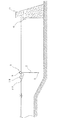
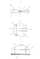
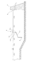
図1および図2に示すように、汚濁防止装置1は、上端にフロート5を備え、下端部にウエイトチェーン3を備えた汚濁防止膜2を有するもので、ダム堤体Dから上流側に所定の距離を設けてダム堤体Dと略平行に設置されている。こうして汚濁防止膜2で、貯水の底層部よりも上方を上流側と下流側とに仕切っている。
As shown in FIGS. 1 and 2, the
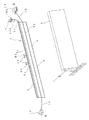
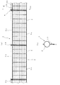
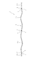
汚濁防止膜2は、図3に示すように、複数の汚濁防止膜単体2aを連結し長さを延長したもので、各汚濁防止膜単体2aには、フロート5を構成している細長い長尺のフロート単体(5aまたは5bの符号を付したもの)と、ウエイトチェーン3を構成しているウエイトチェーン単体3aとが配設されている。
As shown in FIG. 3, the
フロート単体は、浮沈式のフロート単体5aと固定式のフロート単体5bとがあり、中央部分に配置されている2つの汚濁防止膜単体2aには浮沈式フロート単体5aが配設されており、残りの汚濁防止膜単体2aには固定式フロート単体5bが配設されている。そして、固定式フロート単体5bを有する汚濁防止膜単体2aが連続して配置されている部分の一部に、フロート単体の代りに通船ゲート21を設けた汚濁防止膜単体2aが介設されており、メンテナンス等を行う作業船の通行を可能にしている。
The float is divided into a float type float unit 5a and a fixed type float unit 5b, and the two pollution prevention membrane units 2a arranged in the central portion are provided with the float type float unit 5a, and the rest A fixed float single body 5b is disposed on the pollution prevention film single body 2a. And the pollution prevention membrane single-piece | unit 2a which provided the
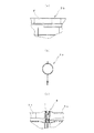
固定式フロート単体5bは、図4(a)に示すように、ターポリンを細長い袋状に縫製し、その中に浮力体として直径約400mmの円柱状の発泡スチロールFを寝かせた状態で収納したもので、常時水面に浮かんだ状態になっている。一方、浮沈式フロート単体5aは、図4(b)に示すように、耐候性等の物性を備えた合成ゴム製の直径約400mmの円形断面を有するゴムチューブで、内部に空気を出し入れできるようになっている。 As shown in FIG. 4 (a), the fixed type float 5b is obtained by sewing a tarpaulin into a slender bag shape and storing a cylindrical foam F having a diameter of about 400 mm as a buoyant body in a laid state. , Always floating on the surface of the water. On the other hand, as shown in FIG. 4B, the float / sink type float unit 5a is a synthetic rubber rubber tube having a circular section having a diameter of about 400 mm and having physical properties such as weather resistance, so that air can be taken in and out. It has become.
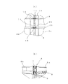
フロート単体5a・5bどうしは、図4(c)に示すように、連結金具6を介して連結されており、各連結金具6にはその自重によって連結部が沈まないようにするため、箱型のFRP(繊維強化プラスチック)製の補助フロート7が、両面から挟み込むように取付けられている(図5(a)参照)。
As shown in FIG. 4 (c), the floats 5a and 5b are connected to each other via connecting
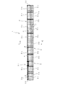
各フロート単体5a・5bには、引張強度800kgf/3cmのポリエステル製シートで形成されている横長の長方形状の膜体が、下端が水深10〜15mに達するような長さで吊設された状態となっている。膜体は、図5(b)に示すように、格子状に補強ベルト8が縫着されており、図5(c)に示すように、下端部にはエポキシタール塗装が施されたウェイトチェーン3aが取付けられている。
In each float 5a, 5b, a horizontally long rectangular film body formed of a polyester sheet having a tensile strength of 800 kgf / 3 cm is suspended in such a length that the lower end reaches a water depth of 10 to 15 m. It has become. As shown in FIG. 5 (b), the film body has a reinforcing
そして、隣合う汚濁防止膜単体2aの膜体どうしは、図6(a)に示すように、側端部どうしを紐で結び合い連結するとともに、横向きの補強ベルト8の端部に取り付けているD管10にシャックル11を取り付け補強ベルト8どうしを連結することで繋がれている。
And as shown to Fig.6 (a), while adjoining the film body of the pollution prevention film single-piece | unit 2a, a side end part is tied and connected with a string, and it attaches to the edge part of the
また汚濁防止膜単体2aの膜体には、横向きの補強ベルト8と平行に、帯状のポリエステル製抗流水圧ベルト22が縫着されている。隣合う汚濁防止膜単体2aに設けられている抗流水圧ベルト22どうしは、補強ベルト8と同様に端部のD管10どうしをシャックル11で連結して繋げられている。
Further, a belt-like polyester anti-flow
こうして連結されている抗流水圧ベルト22の両端は、岸に設置されたアンカーブロック12にロープ13でそれぞれ取り付けられ張設されている。
Both ends of the anti-flow
そして一方の岸Bには、給気用のコンプレッサー14が設置されており図2参照)、コンプレッサー14に一端が接続され対岸に向かって延びる給排気ホース15は、途中で分岐されて、図7(a)(b)に示すようにコンプレッサー14のある岸Bに近い方の浮沈式フロート単体5aの端部と、隣の浮沈式フロート単体5aの反対側の端部(コンプレッサー14があるのとは反対側の岸Bに近い方)にそれぞれ連結されている。この給排気ホース15の陸上部分には、排気バルブ15aと給排気切替バルブ15bとが介設されている。
On one bank B, an air supply compressor 14 is installed (see FIG. 2). One end of the air supply /
そして浮沈式フロート単体5aは連結部において、端部どうしが短い連通ホース18で連結され、空気が両方の浮沈式フロート単体5a内部を流通可能となっている。 The float / float type float unit 5a is connected at the connecting portion by a communication hose 18 having short ends, so that air can flow through both the float / float type float units 5a.
また各浮沈式フロート単体5aの近傍には、内部に浮力体が収納され常時水面に浮いた状態の浮き子19が設置されており、浮沈式フロート単体5aと長さ約3mのロープ20で連結されている(図1および図2参照)。このロープ20の長さは、上流側河川の水深や流入する水の状態等に応じて適宜設定されている。
In addition, a
なお、浮沈式フロート単体5aが配設された汚濁防止膜単体2aと、通船ゲート21とが配設された汚濁防止膜単体2aとの間には、抗流水圧ベルト22の強度を低く設定した汚濁防止膜単体2aが配置されており、装置に想定した以上の流水圧が作用した場合、初めにこの汚濁防止膜単体2aが(ブレーカーフェンスとも言う)が破損し、装置の耐久性の目安とすることができる。したがって、この汚濁防止膜単体2aが破損すれば装置を回収し、それ以上の装置の損傷を防ぐことができる。
In addition, the strength of the anti-flow
次に、この汚濁防止装置1の操作手順について説明する。
Next, the operation procedure of this
ダムの放流を行なわないときには、フロート5を水面に浮上させ、汚濁防止膜2で貯水の底層部より上方を上流側と下流側とに仕切る(図1参照)。そして、上流側河川から流入する水を汚濁防止膜2の上流側に滞留させて、水に含まれている土や砂などの濁り成分の沈降を促し、汚濁防止膜2の下流側の貯水が濁らないようにする。
When the dam is not discharged, the
そして、上流側河川から濁りの少ない水が流入しているような平時において放流を行う場合には、放流ゲートGを開く前に排気バルブ15aを開状態にする(このとき給排気切替バルブ15bは閉状態)。すると、二本の浮沈式フロート単体5a内部の空気が、給排気ホース15を通して排気バルブ15aから外部に排出される。
Then, when discharging at a normal time when water with less turbidity flows from the upstream river, the exhaust valve 15a is opened before opening the discharge gate G (at this time, the supply / exhaust switching valve 15b is Closed). Then, the air inside the two float / float type single floats 5 a is discharged to the outside from the exhaust valve 15 a through the air supply /
こうして二本の浮沈式フロート単体5aの浮力を低下させることで、浮沈式フロート単体5a等の自重、ウエイトチェーン3の重みによって沈下させる。沈下した浮沈式フロート単体5aは、水面の浮き子19と約3mの長さのロープ20で連結されているため、図8に示すように、水深約3mの位置で停止する。すると汚濁防止膜2で仕切られていた貯水の上層部が、上流側と下流側とで流通可能になる。
In this way, by lowering the buoyancy of the two float / float type floats 5a, the float / sink type floats 5a and the like are lowered by their own weight and the weight of the
この状態でダム堤体の放流ゲートGを開くと、上流側河川から流入している濁りの少ない水は、沈下している浮沈式フロート単体5aの上側を通り、放流ゲートGにスムーズに導かれる。このため貯水を濁らせるような攪拌する流れが生じず、濁りの少ない澄んだ水を下流側河川へ放流できるようになる。 When the discharge gate G of the dam dam body is opened in this state, the water with less turbidity flowing from the upstream river passes smoothly above the sinking float unit 5a and is smoothly guided to the discharge gate G. . For this reason, the flow of stirring that makes the stored water turbid does not occur, and clear water with less turbidity can be discharged to the downstream river.
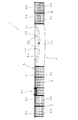
また貯水の放流時には、上流側から放流ゲートGへ向かう流速の早い水流が発生しているため、汚濁防止膜2はこの流水による大きな流水圧を受けることとなる。そして、汚濁防止膜2は、流水圧によって下流側に押されるものの、両端を両岸Bのアンカー12に取り付られ張設されている抗流水圧ベルト22によって流水圧に抗するように支持される。
Further, when the stored water is discharged, a water flow having a high flow velocity from the upstream side toward the discharge gate G is generated, so that the
これによって抗流水圧ベルト22より下側の汚濁防止膜2は、図9に示すように、ウエイトチェーン3の重さによって、ほぼ真下に向かって吊設された状態を維持しているが、抗流水圧ベルト22の上側の汚濁防止膜単体2a(浮沈式フロート単体5a含む)には、抗流水圧ベルト22を支点として下流側に押し倒すような力が作用する。したがって、上方向の力が作用しにくくなるため、浮沈式フロート単体2aは浮き上がにくい状態となる。
As a result, as shown in FIG. 9, the
この場合、浮沈式フロート単体5aの下端部や汚濁防止膜単体2aの上端部に、沈下用の補助重錘としてウエイトブロック9を取り付けておくと、より確実に流水圧による浮き上がりを防止することができる(図6(b)参照)。また二本の浮沈式フロート単体2aの中央部近傍、つまり連結部付近のウエイトブロック9の重さを重くしたり、ピッチを狭くして配置しておくと、沈下させる際に中央部分から沈下が始まり、給排気ホース15が接続されている両側からスムーズに空気を排出させることができるため、空気が内部に残留することもなく、浮沈式フロート単体2aを確実、且つ素早く沈下させることが可能となる。さらに、浮沈式フロート単体2aと固定式フロート単体5bとの連結部が、浮沈式フロート単体2aの沈下に伴って沈むことを防止することもできる。
In this case, if the
放流が終われば放流ゲートGを閉じ、排気バルブ15aを閉状態にするとともに、給排気切替バルブ15bを開状態にし、コンプレッサー14を駆動する。そして、給排気ホース15から圧縮空気を各浮沈式フロート単体5aに供給して浮力を与え水面に浮上させる。
When the discharge is completed, the discharge gate G is closed, the exhaust valve 15a is closed, the supply / exhaust switching valve 15b is opened, and the compressor 14 is driven. Then, compressed air is supplied from the supply /
なお本実施形態では、通船ゲート21を設けているが、浮沈式フロート単体5aを沈下させて作業船を通行させるようにすれば、通船ゲート21を省略でき構造をシンプルにすることができる。
In this embodiment, the
このように構成されている汚濁防止装置は、図10に示すように、浮沈式フロート単体5aの長手方向の長さを、水面に浮上した際弛んだ状態になるように余長を持たせておくこともできる。この場合、浮沈式フロート単体5aの長手方向の全長にわたって取り付けられている汚濁防止膜に、その横方向の長さよりも短い抗流水圧ベルトを、汚濁防止膜単体の余長分を折り畳んだ状態で縫着する。 As shown in FIG. 10, the pollution prevention apparatus configured in this way has a length in the longitudinal direction of the float-float type float unit 5 a so as to be loose when it floats on the water surface. It can also be left. In this case, in a state where the anti-flow hydraulic pressure belt shorter than the lateral length is folded on the anti-contamination membrane attached over the entire length in the longitudinal direction of the float / sink type float unit 5a, the extra length of the anti-contamination membrane unit is folded. Sewing.
こうして浮沈式フロート単体5aに余長を持たせておくことで、沈下する際、両側の固定式フロート単体5bに引張られにくくなりスムーズに沈めることができる。またこのような浮沈式フロート単体5aに取り付けている汚濁防止膜は、上側部分にだけ余長を持たせるようにしても良く、例えば、抗流水圧ベルトより上側の汚濁防止膜単体を逆台形状にして上側を幅広のものとしても良い。 In this way, by allowing the float / sink type float unit 5a to have an extra length, when sinking, it is difficult to be pulled by the fixed type float unit 5b on both sides so that it can be smoothly sunk. Further, the anti-contamination membrane attached to the float / float type float unit 5a may have an extra length only in the upper portion, for example, the anti-contamination membrane unit above the anti-flow hydraulic belt is inverted trapezoidal. The upper side may be wide.
またフロートを、浮沈式フロート単体のみで構成して、フロート全体を沈下させて、貯水上層部を流通させるようにしても良い。 Further, the float may be constituted by only the float / sink type float, and the entire float may be sunk to circulate the stored water upper layer.
それから抗流水圧ベルトの代わりに、ウエイトチェーンの両端をロープ等で陸上のアンカーに取り付けて張設することで、抗流水圧用のテンション部とした場合にも、抗流水圧ベルトと同じように浮沈式フロート単体等の浮き上がりを防止することができる。 Then, instead of the anti-flow hydraulic pressure belt, both ends of the weight chain are attached to the land anchors with ropes, etc. It is possible to prevent the floating of the single type float or the like.
一方、放流に伴う水流の速度が遅いなど、汚濁防止膜にかかる流水圧が弱い場合には、汚濁防止膜の自重やウエイトチェーンの重みで、沈下した浮沈式フロート単体の浮き上がりを防止することができるので、抗流水圧ベルトを省いて構造をシンプルにすることができる。この場合、汚濁防止膜は膜体に設けた補強ベルト(テンションベルト)やフロート等の両端をアンカーロープ等で岸のアンカーブロック等に係留しておく。 On the other hand, when the water pressure applied to the pollution control film is weak, such as when the water flow speed associated with the discharge is slow, it is possible to prevent the floating float / float type float from rising due to the weight of the pollution prevention film and the weight of the weight chain. Since it can, the anti-flow hydraulic belt can be omitted and the structure can be simplified. In this case, the anti-fouling film is moored at both ends of a reinforcement belt (tension belt), a float, etc. provided on the film body with an anchor rope or the like on the shore anchor block.
そして、浮沈式フロート単体を沈下させる場合には、内部の空気を排出して浮力を失わせ、自重やウエイトチェーンの重みで沈下させるが、浮沈式フロート単体が配設されている汚濁防止膜単体どうしの連結部近傍に位置するウエイトチェーンを重くしたり、二重に設けるなどしておくと、前記浮沈式フロート単体を確実、且つ素早く沈下させることができる。つまり、浮沈式フロート単体の空気を排出して浮力を失わせると、浮沈式フロート単体の連結部分から沈下が始まり、給排気ホースが接続されている両側から、空気を残留させることなくスムーズに排出させることができるからである。さらに、浮沈式フロート単体と固定式フロート単体との連結部が、浮沈式フロート単体の沈下に伴って沈むことを防止することもできる。 And when sinking a float-float type float alone, the inside air is discharged to lose buoyancy and sink due to its own weight or the weight of the weight chain. If the weight chains located in the vicinity of the connecting portions are made heavy or doubled, the float / float type float can be sunk reliably and quickly. In other words, if the buoyancy is lost by discharging the air of the float / float float unit, the settlement starts from the connecting part of the float / float float unit, and the air is smoothly discharged from both sides to which the air supply / exhaust hose is connected without remaining. It is because it can be made. Furthermore, it is possible to prevent the connecting portion between the float / sink type float unit and the fixed type float unit from sinking as the float / sink type float unit sinks.
それから浮沈式フロート単体の沈下深さを、供給する空気量によって調節しても良く、この場合には、浮き子を過剰な沈下を抑える安全装置として用いることもできる。また排気バルブや給排気切替バルブの数や位置は任意に設定することができ、例えば、これらのバルブをフロートに取り付けて水上に配置するようにし、遠隔操作により作動させる構成とすることもできる。 Then, the subsidence depth of the float / float type float unit may be adjusted by the amount of air to be supplied. In this case, the float can be used as a safety device for suppressing excessive settlement. Further, the number and position of the exhaust valves and the supply / exhaust switching valves can be arbitrarily set. For example, these valves can be mounted on the float and disposed on the water, and can be configured to be operated by remote operation.
1 汚濁防止装置
2 汚濁防止膜
3 ウエイトチェーン
5 フロート
5a 浮沈式フロート単体
5b 固定式フロート単体
14 アンカー
19 浮き子
22 抗流水圧ベルト
D ダム堤体
DESCRIPTION OF
Claims (7)
前記汚濁防止膜の前記フロートの少なくとも一部を、貯水の底層部よりも上方において沈下させることにより、貯水の上層部を前記汚濁防止膜の上流側から下流側へ流通させるように構成したこと
を特徴とする汚濁防止装置。 The bottom layer of the water storage is provided with a pollution prevention membrane equipped with a float at the top and a weight such as a chain at the bottom at a distance from the dam dam body to the upstream side and approximately parallel to the dam dam body. An anti-contamination device that prevents turbidity of stored water on the downstream side by partitioning the upper side into an upstream side and a downstream side with the anti-contamination membrane,
The upper layer part of the stored water is circulated from the upstream side to the downstream side of the pollution control film by sinking at least a part of the float of the pollution prevention film above the bottom layer part of the stored water. A pollution control device.
前記フロートの長手方向の一部を浮沈式フロートで構成し、この浮沈式フロートを水面に浮上させた際弛んだ状態となるように余長を持たせ、前記浮沈式フロートを、貯水の底層部よりも上方において沈下させることにより、貯水の上層部を前記汚濁防止膜の上流側から下流側へ流通させるように構成したこと
を特徴とする濁防止装置。 The bottom layer of the water storage is provided with a pollution prevention membrane equipped with a float at the top and a weight such as a chain at the bottom at a distance from the dam dam body to the upstream side and approximately parallel to the dam dam body. An anti-contamination device that prevents turbidity of stored water on the downstream side by partitioning the upper side into an upstream side and a downstream side with the anti-contamination membrane,
A part of the float in the longitudinal direction is composed of a float / float type float, and when the float / float type float is floated on the water surface, it has a surplus length so as to be loosened. An anti-turbidity device characterized in that the upper layer portion of the stored water is circulated from the upstream side to the downstream side of the anti-contamination membrane by being submerged above.
Claim that the subsidence depth of the float or the subsidence type float is limited by connecting the subsidence part of the float or the subsidence float to a float installed on the water surface with a rope. Item 7. The pollution control device according to any one of Items 1 to 6.
Priority Applications (1)
| Application Number | Priority Date | Filing Date | Title |
|---|---|---|---|
| JP2004104245A JP2005290719A (en) | 2004-03-31 | 2004-03-31 | Contamination preventing apparatus |
Applications Claiming Priority (1)
| Application Number | Priority Date | Filing Date | Title |
|---|---|---|---|
| JP2004104245A JP2005290719A (en) | 2004-03-31 | 2004-03-31 | Contamination preventing apparatus |
Publications (1)
| Publication Number | Publication Date |
|---|---|
| JP2005290719A true JP2005290719A (en) | 2005-10-20 |
Family
ID=35323968
Family Applications (1)
| Application Number | Title | Priority Date | Filing Date |
|---|---|---|---|
| JP2004104245A Pending JP2005290719A (en) | 2004-03-31 | 2004-03-31 | Contamination preventing apparatus |
Country Status (1)
| Country | Link |
|---|---|
| JP (1) | JP2005290719A (en) |
Cited By (3)
| Publication number | Priority date | Publication date | Assignee | Title |
|---|---|---|---|---|
| JP2010095851A (en) * | 2008-10-14 | 2010-04-30 | Kaiwa Tec Kk | Navigation gate |
| JP2013002155A (en) * | 2011-06-17 | 2013-01-07 | Marsima Aqua System Corp | Sink-and-float type fence |
| JP2015101878A (en) * | 2013-11-25 | 2015-06-04 | 海和テック株式会社 | Contamination preventive film device |
-
2004
- 2004-03-31 JP JP2004104245A patent/JP2005290719A/en active Pending
Cited By (3)
| Publication number | Priority date | Publication date | Assignee | Title |
|---|---|---|---|---|
| JP2010095851A (en) * | 2008-10-14 | 2010-04-30 | Kaiwa Tec Kk | Navigation gate |
| JP2013002155A (en) * | 2011-06-17 | 2013-01-07 | Marsima Aqua System Corp | Sink-and-float type fence |
| JP2015101878A (en) * | 2013-11-25 | 2015-06-04 | 海和テック株式会社 | Contamination preventive film device |
Similar Documents
| Publication | Publication Date | Title |
|---|---|---|
| US20050058509A1 (en) | Floating modular breakwater | |
| US5385427A (en) | Method and apparatus for containment of oil and other pollutants | |
| US8979427B2 (en) | Coastal recovery utilizing repositionable shoal module | |
| US20210214048A1 (en) | System and method for controlling a structure suspended in water | |
| US6485230B2 (en) | Submersible modular dike and method for segregating body of water | |
| CN105155464B (en) | A kind of kickboard device reinforced that promotees to become silted up for mattress sinking | |
| CN101855131B (en) | Offshore structure, buoyant structure, and method of installing an offshore structure | |
| CN107354912A (en) | Floating grid type subtracts stream wave absorption structure | |
| JP2005290719A (en) | Contamination preventing apparatus | |
| US20030044233A1 (en) | Porous groin with flotation support | |
| JP4636985B2 (en) | Pollution prevention device | |
| KR20070104066A (en) | Small Ship Buoy | |
| JP5269541B2 (en) | Passage gate | |
| JPH1121866A (en) | Oil fence | |
| WO2005105568A1 (en) | Simple mariner system and method for managing vessel | |
| CN109736258B (en) | Method for preventing silt from silting | |
| US7618214B2 (en) | Containment boom guide system and method | |
| JPS6040406A (en) | Flexible film dam | |
| JP4637025B2 (en) | Pollution control device and mooring method of pollution control device | |
| US20050036839A1 (en) | Porous groin with flotation support | |
| EP4190994A2 (en) | Mobile bathing site | |
| KR101399605B1 (en) | Floating dock device and method for building structure | |
| JP6202675B2 (en) | Pollution prevention membrane device | |
| EP1463861A1 (en) | Device for a total, or partial, operating barrier for a channel and its installation | |
| RU2014380C1 (en) | Screen for protection of water from pollution with ground during underwater earth-moving work |
Legal Events
| Date | Code | Title | Description |
|---|---|---|---|
| A621 | Written request for application examination |
Free format text: JAPANESE INTERMEDIATE CODE: A621 Effective date: 20070320 |
|
| A521 | Written amendment |
Free format text: JAPANESE INTERMEDIATE CODE: A523 Effective date: 20071101 |
|
| A711 | Notification of change in applicant |
Effective date: 20071101 Free format text: JAPANESE INTERMEDIATE CODE: A711 |
|
| A521 | Written amendment |
Effective date: 20071101 Free format text: JAPANESE INTERMEDIATE CODE: A821 |
|
| A131 | Notification of reasons for refusal |
Effective date: 20080108 Free format text: JAPANESE INTERMEDIATE CODE: A131 |
|
| A521 | Written amendment |
Effective date: 20080307 Free format text: JAPANESE INTERMEDIATE CODE: A523 |
|
| A02 | Decision of refusal |
Effective date: 20080708 Free format text: JAPANESE INTERMEDIATE CODE: A02 |