JP2005290417A - Method and apparatus for capturing droplet in physical film forming method - Google Patents
Method and apparatus for capturing droplet in physical film forming method Download PDFInfo
- Publication number
- JP2005290417A JP2005290417A JP2004103219A JP2004103219A JP2005290417A JP 2005290417 A JP2005290417 A JP 2005290417A JP 2004103219 A JP2004103219 A JP 2004103219A JP 2004103219 A JP2004103219 A JP 2004103219A JP 2005290417 A JP2005290417 A JP 2005290417A
- Authority
- JP
- Japan
- Prior art keywords
- filter plate
- droplet
- droplets
- capturing
- target
- Prior art date
- Legal status (The legal status is an assumption and is not a legal conclusion. Google has not performed a legal analysis and makes no representation as to the accuracy of the status listed.)
- Granted
Links
Images


Landscapes
- Physical Vapour Deposition (AREA)
- Physical Deposition Of Substances That Are Components Of Semiconductor Devices (AREA)
Abstract
【課題】回転フィルター板に使用時間とともに蓄積していたドロップレットを、捕捉しながら回収して、長期間の連続動作を可能にするとともにドロップレットの清掃のための回転フィルター板の取り外しを不要とする。
【構成】ターゲットから発生するドロップレットを、基板とターゲットの間に取り付けられた回転フィルター板を備えたロップレット捕捉手段で捕捉し、かつ回転フィルター板の回転軸周辺に向心力により流動させて回収することを特徴とする物理的成膜法におけるドロップレットの捕捉方法と装置。
【選択図】 図6
[PROBLEMS] To collect and collect droplets that have accumulated on a rotating filter plate over time to enable continuous operation over a long period of time and eliminate the need to remove the rotating filter plate for cleaning the droplets. To do.
[Structure] Droplets generated from a target are captured by a loplet capturing means having a rotating filter plate attached between the substrate and the target, and flowed around the rotating shaft of the rotating filter plate by a centripetal force and recovered. A method and an apparatus for capturing droplets in a physical film forming method.
[Selection] Figure 6
Description
本発明は、レーザーアブレーション法、スパッタリング法、アーク放電法などの物理的成膜法においてターゲットから飛翔する微粒子にともなうドロップレットと呼ばれる粗大微粒子を選択的に捕捉するための方法及び装置に関するものである。 The present invention relates to a method and an apparatus for selectively capturing coarse particles called droplets accompanying fine particles flying from a target in a physical film forming method such as a laser ablation method, a sputtering method, or an arc discharge method. .
レーザーアブレーション成膜方法における従来のドロップレット捕捉技術としては、回転式フィルター円板を用いた方法(特許文献1)や回転羽根を用いた方法(特許文献2)などの回転フィルター方式があるが、前者は、レーザーはパルス状照射となりフィルターとの同期をとる必要があり、選択する速度範囲が限定され、後者は、羽根に角度があるために羽根がドロップレットを捕獲せずに反射してしまうため、低速成分であるドロップレットを完全に捕捉できない、低速成分を捕捉するための羽根の設計が極めてシビアで多数の羽根の設置が困難なために、フィルターの粒子飛翔方向の厚みを大きくする必要があり、その結果、ターゲットと基板間距離を大きくせざるを得ず、良質な膜を得にくいなどの問題がある。さらに、ともにフィルターの製作に極めて高度な技術が要求されるので高価であり、また一度捕捉されたドロップレットが再放出しやすい欠点があった。 As a conventional droplet capturing technique in the laser ablation film forming method, there is a rotating filter method such as a method using a rotating filter disk (Patent Document 1) and a method using a rotating blade (Patent Document 2). In the former, the laser is pulsed and needs to be synchronized with the filter, and the speed range to be selected is limited. In the latter, since the blade has an angle, the blade reflects without capturing the droplet. Therefore, it is necessary to increase the thickness of the filter in the particle flight direction because the design of the blade for capturing the low speed component is extremely severe and it is difficult to install a large number of blades. As a result, the distance between the target and the substrate has to be increased, and there is a problem that it is difficult to obtain a high-quality film. Further, both of them are expensive because a very advanced technique is required for manufacturing the filter, and there is a drawback that the droplets once captured are likely to be re-released.
本発明者は、それらの欠点を克服するために多数の羽根を回転面に対して垂直に配置し高速回転させる方法に係わる発明を特許出願した(特許文献3)。また、メッシュ状、格子状、渦巻き状の隙間を設けた微粒子通過面積コントロール板を用いる方法も考えられている(特許文献4)。しかし、いずれも、フィルターに付着したドロップレットの回収は考慮されておらず、フィルターにドロップレットが多量に堆積した場合には、フィルターを取り外してオーバーホールするかあるいは交換せざるを得なかった。 In order to overcome these drawbacks, the inventor has filed a patent application for an invention relating to a method of rotating a plurality of blades perpendicularly to a rotating surface and rotating them at high speed (Patent Document 3). Further, a method using a fine particle passage area control plate provided with a mesh, lattice, or spiral gap is also considered (Patent Document 4). However, in any case, collection of droplets adhering to the filter was not considered, and when a large amount of droplets accumulated on the filter, the filter was removed and overhauled or replaced.
本発明は、回転フィルター板に使用時間とともに蓄積していたドロップレットを、捕捉しながら回収して、長期間の連続動作を可能にするとともにドロップレットの清掃のための回転フィルター板の取り外しを不要とすることを課題とする。 The present invention collects and collects droplets accumulated in the rotating filter plate over time, enabling continuous operation over a long period of time and eliminating the need to remove the rotating filter plate for cleaning the droplets. The problem is to do.
上記の課題を解決するために、本発明は、回転フィルター板の回転中心周辺から外側方向へ渦を巻いて放射状に外側へ向かって広がる羽根を設けて、各羽根の間に微粒子が飛翔して通過する隙間を設け、フィルター板の回転によって隙間を通過できずに隙間内に捕捉されたドロップレットがフィルター板の回転による向心力を受けフィルター板の中央部分に流動することを利用して、ドロップレットの回収を行うことを特徴とする。 In order to solve the above problems, the present invention provides blades that vortex outward from the periphery of the rotation center of the rotary filter plate and spread radially outward, and fine particles fly between the blades. By using the fact that the droplet trapped in the gap without passing through the gap due to rotation of the filter plate receives the centripetal force due to rotation of the filter plate and flows to the center part of the filter plate It collect | recovers.
上記の構造の回転フィルター板を用いた場合、ターゲット側のフィルター板表面での回転方向の羽根間の隙間の間隔をX、Xの中間点までのフィルター板回転軸中心からの距離をRとすると、フィルター板によって捕捉可能な微粒子の最大速度Vmax(単位=mm/秒)は、Vmax= (1/2)h ω / tan-1(X/2R)と与えられる。但し、hはフィルター板の微粒子飛翔方向の厚さh(単位=mm)、ωはフィルターの角速度(単位=ラジアン/秒)であり
、羽根間の隙間の間隔Xはフィルター板の表と裏で同一とする。フィルター板面の外側寄りと内側寄りとで捕捉最大速度を統一する場合は、内側寄りの羽根間の隙間の間隔は小さく、外側寄りの羽根間の隙間の間隔は大きくする必要がある。その一方で、羽根間の隙間の間隔をフィルター板の位置で変化させることで、フィルター板の捕捉特性を位置によってフレキシブルに変化させることが出来る。
When the rotary filter plate having the above structure is used, the gap between the blades in the rotation direction on the surface of the filter plate on the target side is X, and the distance from the filter plate rotation axis center to the middle point of X is R. The maximum velocity Vmax (unit = mm / second) of the fine particles that can be captured by the filter plate is given by Vmax = (1/2) h ω / tan −1 (X / 2R). Where h is the thickness h (unit = mm) of the filter plate in the particle flight direction, ω is the angular velocity of the filter (unit = radians / second), and the gap X between the blades is the front and back of the filter plate. Identical. In the case where the maximum capture speed is unified between the outer side and the inner side of the filter plate surface, the gap between the inner blades needs to be small and the gap between the outer blades needs to be large. On the other hand, by changing the gap between the blades at the position of the filter plate, the capture characteristics of the filter plate can be flexibly changed depending on the position.
一旦捕捉されたドロップレットが再放出しないように、各羽根の回転フィルター板の厚さ方向、かつ羽根の厚さ方向の断面で見て、回転方向の前側が凹面を有する凹型形状を有するようにする。各羽根の回転方向に見て前側の内面に捕捉されたドロップレットは羽根の該内面の凹部分に沿って再放出することなく、フィルター板の回転による回転軸方向への向心力を受けてフィルター板の中央部分に流動して集まる。したがって、ドロップレットの捕捉動作をさせながらフィルター板の羽根内面に堆積したドロップレットをフィルター板の中央部分に集めることが出来る。 In order to prevent the droplets once trapped from being re-emitted, the front side in the rotational direction has a concave shape with a concave surface when viewed in the thickness direction of the rotating filter plate of each blade and in the thickness direction of the blade. To do. The droplets captured on the inner surface on the front side when viewed in the direction of rotation of each blade are not re-released along the concave portion of the inner surface of the blade, and receive the centripetal force in the direction of the rotation axis due to the rotation of the filter plate. Gathers in the middle part of Accordingly, the droplets accumulated on the inner surface of the blades of the filter plate can be collected in the central portion of the filter plate while the droplet is captured.
ドロップレットが集まってくるフィルター板の中央部分の下方部には、ドロップレット回収箱を設置する。これによって、真空を開放することなくフィルター板を動作させながら、捕捉したドロップレットを回収することが可能となる。捕捉されたドロップレットが回転軸の周辺部分に向かって容易に流動していくことを可能とするために、羽根は、少なくとも回転方向の前側面が捕捉されるドロップレット材料に対してぬれ性の悪い材料、すなわち、付着しにくい材料で製作するか、該材料でコーティングする。例えば、金属、酸化物、カーボンなどの大部分のターゲット材料に対して、ポリテトラフロロエチレンのようなフッ素樹脂が有効である。その他、耐熱性が必要な場合には、TiNが有効である。 A droplet collection box is installed below the central portion of the filter plate where the droplets gather. This makes it possible to collect the captured droplets while operating the filter plate without releasing the vacuum. In order to allow the captured droplets to flow easily towards the periphery of the axis of rotation, the vanes are at least wettable with respect to the droplet material on which the front side in the rotational direction is captured. Manufactured or coated with a bad material, that is, a material that does not adhere easily. For example, a fluororesin such as polytetrafluoroethylene is effective for most target materials such as metals, oxides, and carbon. In addition, TiN is effective when heat resistance is required.
上記の態様に代えて、回転フィルター板の回転中心周辺から外側方向へ渦を巻いて放射状に外側へ向かって広がる羽根を設けて、各羽根の間に微粒子が飛翔して通過する隙間を設けるとともに、回転フィルター板の上面及び下面に各羽根間の隙間を部分的にマスクするように多数の貫通穴がある板を装着し、該貫通孔を微粒子が飛翔するようにすることで、貫通孔から隙間内に飛翔してきて各羽根の回転方向に見て前側の内面に捕捉したドロップレットの再放出をより強く阻止することが出来る。捕捉したドロップレットは、上記の態様と同じくフィルター板の回転による回転軸方向への向心力を受けフィルター板の回転中心部に集まる。 In place of the above-described embodiment, vanes that vortex outward from the periphery of the rotation center of the rotary filter plate and spread radially outward are provided, and a gap through which fine particles fly and pass is provided between the vanes. By attaching a plate with a large number of through holes so as to partially mask the gaps between the blades on the upper and lower surfaces of the rotary filter plate, and by allowing the fine particles to fly through the through holes, It is possible to more strongly prevent the re-release of the droplets flying in the gap and trapped on the inner surface on the front side when viewed in the rotation direction of each blade. The captured droplets receive a centripetal force in the direction of the rotation axis due to the rotation of the filter plate as in the above-described aspect, and gather at the center of rotation of the filter plate.
この場合、上記の態様に比べて、回転フィルター板の全表面積に対して微粒子が飛翔する貫通穴の占める部分の面積比が減少し、生成する膜の堆積速度が減少する短所があるが、内部の渦巻状の羽根に必ずしも前記のとおりの凹構造を形成する必要がなく、フィルター板を安価に製作できる。 In this case, compared to the above embodiment, the area ratio of the portion occupied by the through holes through which the fine particles fly is reduced with respect to the total surface area of the rotating filter plate, and the deposition rate of the generated film is reduced. It is not always necessary to form the concave structure as described above in the spiral blade, and the filter plate can be manufactured at low cost.
貫通穴の断面形状は、円、楕円、多角形のいかなる場合でも構わない。ドロップレットの捕捉特性は、貫通穴の形状で調整できる。貫通穴が多数ある板を、渦巻き状の羽根フィルター板の表及び裏面に張り合わせることが最も簡便な好ましい方法である。 The cross-sectional shape of the through hole may be any of a circle, an ellipse, and a polygon. The capturing characteristics of the droplet can be adjusted by the shape of the through hole. The simplest and preferred method is to attach a plate having many through holes to the front and back surfaces of a spiral blade filter plate.
以上述べたように、本発明の方法及び装置によれば、回転フィルター板を動作させながら、捕捉したドロップレットを回収することが可能となり、回転フィルター板を利用した成膜において、長期の連続運転が可能となる。回転フィルター板のメンテナンスも、従来の方法に比べて大幅に低減できる。 As described above, according to the method and apparatus of the present invention, it is possible to collect the captured droplets while operating the rotary filter plate, and long-term continuous operation in film formation using the rotary filter plate. Is possible. The maintenance of the rotating filter plate can also be greatly reduced compared to the conventional method.
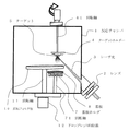
以下、本発明の方法及び装置を図に基づいて具体的に説明する。レーザーアブレーション法のドロップレットの捕捉に用いる場合には、図1に示すように、反応チャンバ1の内
部にレンズ2によって、集光したレーザー光3をターゲットホルダー4に設置したターゲット5に照射して、ターゲット5から発生する微粒子を基板ホルダー7に設置した基板8に付着させる。ターゲットホルダー4と基板ホルダー7はそれぞれ回転軸41,71で回転させる。反応チャンバ1内には雰囲気ガスを適宜供給する。ターゲット5から基板8への微粒子の飛翔経路を遮蔽するように回転フィルター板10を回転軸11で高速回転可能に設置する。回転フィルター板10の回転軸11の下方の反応チャンバ1の外にドロップレットの回収箱12を設ける。
Hereinafter, the method and apparatus of the present invention will be specifically described with reference to the drawings. When used for capturing a droplet of the laser ablation method, as shown in FIG. 1, a focused
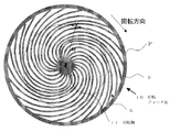
図2に、回転フィルター板10を上から見た概略平面図を示す。回転フィルター板の羽根Bはフィルター板の回転中心周辺から渦を巻いて放射状に外側へ向かって外周のプレートPまで形成し、隣接する羽根と羽根の間に隙間Sを形成する。捕捉されるドロップレットの最大速度は、ターゲット側のフィルター板表面での回転方向の羽根間の隙間Sの間隔XとXの中間点までのフィルター板の回転軸11中心からの距離R、及びフィルター板の回転数によって前述したように決まる。
FIG. 2 shows a schematic plan view of the
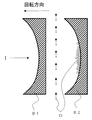
図3に、フィルター板の隣接する二つの羽根B1、B2に着目し、そのフィルター板の厚さ方向に平行、かつ羽根の厚さ方向に見た断面図を示す。羽根B1、B2は、回転方向前側が凹面状になり深さ方向の内部にいくに従い肉厚が薄くなるように設計されている。このことによって、図3に示すように、回転方向前側の内面Iに捕捉されたドロップレットは羽根の内面の凹部分の中央付近に集められ、再放出しにくくなる。 FIG. 3 shows a cross-sectional view in which the two blades B1 and B2 adjacent to each other in the filter plate are focused and viewed in the blade thickness direction parallel to the filter plate thickness direction. The blades B1 and B2 are designed so that the front side in the rotational direction is concave and the thickness is reduced toward the inside in the depth direction. As a result, as shown in FIG. 3, the droplets captured on the inner surface I on the front side in the rotational direction are collected near the center of the concave portion on the inner surface of the blade and are difficult to re-release.
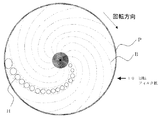
図4に、上記と別の態様の、フィルター板の回転中心周辺から渦を巻いて放射状に外側へ向かって外周の環状プレートPまで広がる羽根Bを有し、かつフィルター板の上面及び下面に各羽根間の隙間Sに多数の円状の貫通穴Hがある板を装着したフィルター板を上から見た概略平面図を示す。フィルター板内部の放射状羽根は点線で示してある。貫通穴Hは、図4に示すように、二つの羽根間に沿って形成する。実際には、貫通穴Hはフィルター板全域に渡って形成される。 FIG. 4 shows blades B that vortex from the periphery of the center of rotation of the filter plate and spread radially outward to the outer peripheral annular plate P, respectively, on the upper and lower surfaces of the filter plate. The schematic plan view which looked at the filter board which mounted | wore with the board | plate with many circular through-holes H in the clearance gap S between blades was seen from the top is shown. The radial vanes inside the filter plate are indicated by dotted lines. The through hole H is formed between two blades as shown in FIG. Actually, the through hole H is formed over the entire area of the filter plate.
図5に、フィルター板内の一つの貫通穴Hの部分に着目し、その断面図を示す。貫通穴は渦巻状の羽根B1,B2の間の隙間の上面と下面に貫通穴Hがある板13,14を装着して形成する。左向きを回転方向とすると、穴Hは羽根B1、B2間の中央より左寄りに形成した方が一旦捕捉した粒子の再放出がおきにくい。羽根B2の回転方向前側の内面に捕捉されたドロップレットは回転軸方向への向心力を受け羽根B2の該内面に沿ってフィルター板の中央部付近に流動して集められる。 FIG. 5 shows a cross-sectional view focusing on one through hole H in the filter plate. The through holes are formed by mounting plates 13 and 14 having through holes H on the upper and lower surfaces of the gap between the spiral blades B1 and B2. If the leftward direction is the rotational direction, the holes H are formed more to the left than the center between the blades B1 and B2, so that the particles once captured are less likely to be released again. The droplets captured on the inner surface on the front side in the rotational direction of the blade B2 receive a centripetal force in the direction of the rotational axis and flow and collect along the inner surface of the blade B2 near the center of the filter plate.
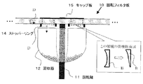
図6に、図2、図3に示すような回転フィルター板を用いる場合の回収箱の周辺の概念図を示す。フィルター板の中央部分に流動してきたドロップレットを、回収箱12に移動させるために、点線部分で囲まれた領域の羽根の断面構造を凹形の構造Bから、回収箱12方向を尖らせた構造B‘に変える。これによって、この点線領域では、集まってきたドロップレットDが回収箱12に向かって落ちていく。回収箱12への隙間からこぼれ落ちないように、点線領域の両側にはストッパーリング14を装着する。また、中央部に集まってきたドロップレットは量が多くなるので、上方へのこぼれ出しを防ぐために、キャップ板15を装着する。 FIG. 6 shows a conceptual diagram of the vicinity of the collection box when the rotary filter plate as shown in FIGS. 2 and 3 is used. In order to move the droplet that has flowed to the center portion of the filter plate to the recovery box 12, the cross-sectional structure of the blades surrounded by the dotted line portion is sharpened from the concave structure B in the direction of the recovery box 12. Change to structure B ′. As a result, in this dotted area, the collected droplets D drop toward the collection box 12. Stopper rings 14 are mounted on both sides of the dotted line area so as not to spill from the gap to the collection box 12. Further, since the amount of droplets gathered at the central portion increases, a cap plate 15 is attached to prevent upward spillage.
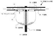
図7に、図4、図5に示すようなフィルター板を用いる場合の回収箱付近の概念図を示す。フィルター板の中央部分に集められてきたドロップレットDを、回収箱12に移動させるために、点線部分で囲まれた領域では下面板14はない。点線領域では、集まってきたドロップレットDが回収箱12に向かって落ちていく。回収箱12への隙間からドロップレットがこぼれ落ちないように、点線領域の両側にはストッパーリング14を装着する。また、フィルター板の中央部に集まってきたドロップレットは量が多くなるので、点線
領域では上面板13に貫通穴は形成しないで上方へこぼれ出ないようにする。
FIG. 7 shows a conceptual diagram of the vicinity of the collection box when the filter plate as shown in FIGS. 4 and 5 is used. In order to move the droplets D collected in the central portion of the filter plate to the collection box 12, there is no lower surface plate 14 in the region surrounded by the dotted line portion. In the dotted line region, the collected droplets D fall toward the collection box 12. Stopper rings 14 are attached to both sides of the dotted line area so that the droplets do not fall out from the gap to the collection box 12. In addition, since the amount of droplets gathered at the center of the filter plate increases, a through hole is not formed in the upper surface plate 13 in the dotted line region so as not to spill upward.
ターボ分子ポンプによって排気された5×10⁻⁷Torr以下の真空チャンバ内において、ArFエキシマレーザー(波長193 nm、FWHM = 20 ns)をSiターゲットに入射角45°で照射し、50 mm離れて対向するガラス基板上に膜堆積を行った。ターゲット−基板間には、高速回転可能な回転フィルター板を設置してドロップレットの捕獲を行った。 ArF excimer laser (wavelength 193 nm, FWHM = 20 ns) is irradiated to Si target at an incident angle of 45 ° in a vacuum chamber of 5 × 10 -7 Torr or less evacuated by a turbo molecular pump, facing 50 mm away Film deposition was performed on a glass substrate. Between the target and the substrate, a rotating filter plate capable of high-speed rotation was installed to capture droplets.
羽根の材料としてステンレス鋼を用い、その表面にフッ化エチレン樹脂をコーティングした。フィルター板の大きさは、直径200mm、厚み10mmとし、凹構造の羽根の厚みは、中心の肉厚の最も薄い部分を0.3mm、両外側の肉厚最大部分を0.8mmとした。 Stainless steel was used as the blade material, and the surface thereof was coated with a fluoroethylene resin. The size of the filter plate was 200 mm in diameter and 10 mm in thickness, and the thickness of the concave blades was 0.3 mm at the thinnest portion of the central thickness, and 0.8 mm at the maximum thickness portions on the outer sides.
図8に、設計したフィルター板の回転速度と捕獲可能な最大速度の関係を示す。フィルター板表面に占める羽根の部分の面積割合は約90%であり、隙間部分の面積は10%であった。レーザーパルスのフルーエンスFは4J/cm2、くり返し周波数は10Hz、基板温度は室温とした。作製したシリコン薄膜中の微粒子の付着具合を走査型電子顕微鏡(SEM)を用いて評価した。 FIG. 8 shows the relationship between the rotation speed of the designed filter plate and the maximum speed that can be captured. The area ratio of the blade portion occupying the surface of the filter plate was about 90%, and the area of the gap portion was 10%. The fluence F of the laser pulse was 4 J / cm 2 , the repetition frequency was 10 Hz, and the substrate temperature was room temperature. The degree of adhesion of fine particles in the produced silicon thin film was evaluated using a scanning electron microscope (SEM).
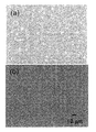
図9に、フィルター板の回転数0(a)と3,500 rpm(b)で、成膜時間60分で作製したシリコン薄膜の膜表面SEM像を示す。3,000 rpm以上ではドロップレットが完全に捕捉されていることがわかる。フィルター板からの一旦捕捉したドロップレットの再放出は観測されなかった。 FIG. 9 shows a SEM image of the film surface of a silicon thin film produced at a rotation speed of 0 (a) and 3,500 rpm (b) of the filter plate and a film formation time of 60 minutes. It can be seen that the droplets are completely captured at 3,000 rpm and above. No re-emission of droplets once trapped from the filter plate was observed.
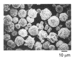
図10に、1000時間後に回収箱に回収されたドロップレットのSEM像を示す。直径10mm前後のドロップレットが多数観測された。回収されたドロップレットの量は約50mgであった。 FIG. 10 shows an SEM image of the droplets collected in the collection box after 1000 hours. Many droplets around 10mm in diameter were observed. The amount of recovered droplets was about 50 mg.
Claims (7)
Priority Applications (1)
| Application Number | Priority Date | Filing Date | Title |
|---|---|---|---|
| JP2004103219A JP4481058B2 (en) | 2004-03-31 | 2004-03-31 | An apparatus for capturing droplets in a physical film forming method. |
Applications Claiming Priority (1)
| Application Number | Priority Date | Filing Date | Title |
|---|---|---|---|
| JP2004103219A JP4481058B2 (en) | 2004-03-31 | 2004-03-31 | An apparatus for capturing droplets in a physical film forming method. |
Publications (2)
| Publication Number | Publication Date |
|---|---|
| JP2005290417A true JP2005290417A (en) | 2005-10-20 |
| JP4481058B2 JP4481058B2 (en) | 2010-06-16 |
Family
ID=35323687
Family Applications (1)
| Application Number | Title | Priority Date | Filing Date |
|---|---|---|---|
| JP2004103219A Expired - Fee Related JP4481058B2 (en) | 2004-03-31 | 2004-03-31 | An apparatus for capturing droplets in a physical film forming method. |
Country Status (1)
| Country | Link |
|---|---|
| JP (1) | JP4481058B2 (en) |
Cited By (1)
| Publication number | Priority date | Publication date | Assignee | Title |
|---|---|---|---|---|
| EP3964605A1 (en) * | 2020-09-03 | 2022-03-09 | Solmates B.V. | Device for pulsed laser deposition |
Citations (2)
| Publication number | Priority date | Publication date | Assignee | Title |
|---|---|---|---|---|
| JPS61170562A (en) * | 1985-01-24 | 1986-08-01 | Sumitomo Metal Ind Ltd | Splash-free vacuum deposition device |
| JPH08176805A (en) * | 1994-12-21 | 1996-07-09 | Minolta Co Ltd | Formation of thin film |
-
2004
- 2004-03-31 JP JP2004103219A patent/JP4481058B2/en not_active Expired - Fee Related
Patent Citations (2)
| Publication number | Priority date | Publication date | Assignee | Title |
|---|---|---|---|---|
| JPS61170562A (en) * | 1985-01-24 | 1986-08-01 | Sumitomo Metal Ind Ltd | Splash-free vacuum deposition device |
| JPH08176805A (en) * | 1994-12-21 | 1996-07-09 | Minolta Co Ltd | Formation of thin film |
Cited By (1)
| Publication number | Priority date | Publication date | Assignee | Title |
|---|---|---|---|---|
| EP3964605A1 (en) * | 2020-09-03 | 2022-03-09 | Solmates B.V. | Device for pulsed laser deposition |
Also Published As
| Publication number | Publication date |
|---|---|
| JP4481058B2 (en) | 2010-06-16 |
Similar Documents
| Publication | Publication Date | Title |
|---|---|---|
| TWI544185B (en) | Ventilator | |
| EP3959945A1 (en) | High brightness laser-produced plasma light source | |
| US20020090054A1 (en) | Apparatus and method for containing debris from laser plasma radiation sources | |
| JP4141933B2 (en) | Film forming apparatus having hole-shaped rotating filter plate for capturing fine particles and film forming method | |
| TW201413190A (en) | Range hood | |
| TW201033470A (en) | Turbo molecular pump and particle trap for turbo molecular pump | |
| JP4481058B2 (en) | An apparatus for capturing droplets in a physical film forming method. | |
| US7302043B2 (en) | Rotating shutter for laser-produced plasma debris mitigation | |
| FR3039424A1 (en) | POROUS FILTER MEDIUM FOR PREVENTING LIQUID TRAINING | |
| JP2019122901A (en) | Mist collector | |
| EP2546187B1 (en) | Getter structure with optimised pumping capacity | |
| JP7798274B2 (en) | High-intensity laser-produced plasma source and radiation generation and collection method | |
| CN110882584A (en) | Dynamic interception purifier | |
| JP2020002464A (en) | Pulse laser vapor deposition for particle reduction of substrate, and apparatus for substrate having substrate surface | |
| JP2009091613A (en) | Film forming method and film forming apparatus | |
| JP2004019493A (en) | Exhaust device | |
| RU89906U1 (en) | DEVICE FOR LASER-PLASMA SPRAYING | |
| KR102827232B1 (en) | Filter for a plasma plume | |
| JP2000215998A (en) | X-ray generator and X-ray device | |
| JP2001068297A (en) | Debris removing mechanism for soft x-ray using device | |
| RU2789275C1 (en) | Target material, high-brightness euv source and 13.5 nm radiation generation method | |
| JPS5933073B2 (en) | Laser removal equipment | |
| WO2018086870A1 (en) | A fuel collector and associated system | |
| JP2015014455A (en) | Range hood | |
| CN211822594U (en) | Smoke collecting hood assembly and range hood |
Legal Events
| Date | Code | Title | Description |
|---|---|---|---|
| A621 | Written request for application examination |
Free format text: JAPANESE INTERMEDIATE CODE: A621 Effective date: 20070228 |
|
| A977 | Report on retrieval |
Free format text: JAPANESE INTERMEDIATE CODE: A971007 Effective date: 20090722 |
|
| A131 | Notification of reasons for refusal |
Free format text: JAPANESE INTERMEDIATE CODE: A131 Effective date: 20090728 |
|
| A521 | Written amendment |
Free format text: JAPANESE INTERMEDIATE CODE: A523 Effective date: 20090925 |
|
| TRDD | Decision of grant or rejection written | ||
| A01 | Written decision to grant a patent or to grant a registration (utility model) |
Free format text: JAPANESE INTERMEDIATE CODE: A01 Effective date: 20100316 |
|
| A01 | Written decision to grant a patent or to grant a registration (utility model) |
Free format text: JAPANESE INTERMEDIATE CODE: A01 |
|
| A61 | First payment of annual fees (during grant procedure) |
Free format text: JAPANESE INTERMEDIATE CODE: A61 Effective date: 20100317 |
|
| FPAY | Renewal fee payment (prs date is renewal date of database) |
Free format text: PAYMENT UNTIL: 20130326 Year of fee payment: 3 |
|
| R150 | Certificate of patent (=grant) or registration of utility model |
Free format text: JAPANESE INTERMEDIATE CODE: R150 |
|
| FPAY | Renewal fee payment (prs date is renewal date of database) |
Free format text: PAYMENT UNTIL: 20130326 Year of fee payment: 3 |
|
| FPAY | Renewal fee payment (prs date is renewal date of database) |
Free format text: PAYMENT UNTIL: 20140326 Year of fee payment: 4 |
|
| R250 | Receipt of annual fees |
Free format text: JAPANESE INTERMEDIATE CODE: R250 |
|
| LAPS | Cancellation because of no payment of annual fees | ||
| S533 | Written request for registration of change of name |
Free format text: JAPANESE INTERMEDIATE CODE: R313533 |
|
| R350 | Written notification of registration of transfer |
Free format text: JAPANESE INTERMEDIATE CODE: R350 |