JP2005287109A - Stator of rotary electric machine - Google Patents
Stator of rotary electric machine Download PDFInfo
- Publication number
- JP2005287109A JP2005287109A JP2004093973A JP2004093973A JP2005287109A JP 2005287109 A JP2005287109 A JP 2005287109A JP 2004093973 A JP2004093973 A JP 2004093973A JP 2004093973 A JP2004093973 A JP 2004093973A JP 2005287109 A JP2005287109 A JP 2005287109A
- Authority
- JP
- Japan
- Prior art keywords
- coil
- conductor
- integer
- conductors
- stator
- Prior art date
- Legal status (The legal status is an assumption and is not a legal conclusion. Google has not performed a legal analysis and makes no representation as to the accuracy of the status listed.)
- Granted
Links
Images


Classifications
-
- H—ELECTRICITY
- H02—GENERATION; CONVERSION OR DISTRIBUTION OF ELECTRIC POWER
- H02K—DYNAMO-ELECTRIC MACHINES
- H02K3/00—Details of windings
- H02K3/04—Windings characterised by the conductor shape, form or construction, e.g. with bar conductors
- H02K3/28—Layout of windings or of connections between windings
Abstract
Description
この発明は、モータや発電機等の回転電機に使用される固定子に関するものであり、特に、コイルが整列巻された分布巻き構造における結線構造に関するものである。 The present invention relates to a stator used in a rotating electrical machine such as a motor or a generator, and more particularly to a connection structure in a distributed winding structure in which coils are aligned and wound.
回転機の固定子は、固定子鉄心と、固定子鉄心に装着されたコイルと、スロット内に装着されてコイルを固定子鉄心から絶縁するインシュレータとを備えている。 The stator of the rotating machine includes a stator core, a coil mounted on the stator core, and an insulator mounted in the slot to insulate the coil from the stator core.
例えば、固定子鉄心は、薄い鋼板を重ねて積層した円筒状のものがあり、中心軸方向に延びるスロットが内周側に開口するように所定ピッチで周方向に複数個設けられている。固定子鉄心にコイルを装着する際には、固定子鉄心を帯状にしてスロットの間隙をコイル導体の線幅より大きくし、太い線幅の導体を装着できるようにしたものがある。このような固定子鉄心では、コイルを装着した後、帯状の固定子鉄心の両端が突き合わされて円環状にされ、両端が溶接等により接合される。 For example, the stator core has a cylindrical shape in which thin steel plates are stacked and laminated, and a plurality of slots extending in the central axis direction are provided in the circumferential direction at a predetermined pitch so as to open to the inner circumferential side. When a coil is mounted on a stator core, a stator core is band-shaped so that the gap between the slots is larger than the line width of the coil conductor so that a conductor having a thick line width can be mounted. In such a stator core, after mounting the coil, both ends of the belt-shaped stator core are butted into an annular shape, and both ends are joined by welding or the like.
コイルの形状としては、固定子鉄心の軸方向端面の外側において、コイルに用いる導線のコイルエンドを折り返して波巻きした構造のものがあり、スロットのスペースを効率よく使うために、2本1組の導線がスロットの深さ方向の内層と外層を交互に採るように所定のスロット数毎にコイルを2組装着し、このコイルを6相に分布巻きしたものがある(例えば、特許文献1参照)。 As the shape of the coil, there is a structure in which the coil end of the conducting wire used for the coil is folded and wound outside the axial end surface of the stator core. In order to use the slot space efficiently, a set of two 2 sets of coils are mounted for each predetermined number of slots so that the lead wires of the inner and outer layers are alternately arranged in the depth direction of the slots, and these coils are distributed in six phases (see, for example, Patent Document 1). ).
回転機の性能はコイルのターン数の影響が大きく、ターン数が限定されると用途に応じた適正な性能設計ができない。 The performance of the rotating machine is greatly influenced by the number of turns of the coil, and if the number of turns is limited, an appropriate performance design according to the application cannot be performed.
例えば、回転機を自動車の交流発電機に用いた場合、発電機の出力電流と回転子の回転数に比例するエンジンの回転数との関係を見た場合、コイルのターン数が多い発電機は、コイルのターン数が少ない発電機と比較して、低速での出力電流は低く、高速での出力電流が高くなる。低速と高速での出力電流のバランスに対して様々なニーズがあるが、スロット中のコイルの数は特定され、コイルのターン数は整数となるので、上記ニーズに対して応えられない場合が生じるという問題がある。 For example, when a rotating machine is used for an AC generator of an automobile, a generator with a large number of coil turns is considered when the relationship between the output current of the generator and the rotational speed of the engine proportional to the rotational speed of the rotor is seen. Compared with a generator with a small number of coil turns, the output current at low speed is low and the output current at high speed is high. There are various needs for the balance between the output current at low speed and high speed, but the number of coils in the slot is specified and the number of turns of the coil is an integer, so the above needs may not be met. There is a problem.
この問題の解決策として、整数ターンコイルのΔ結線と整数ターンコイルのY結線とを組み合わせた構成のものがある。この構成では、整数ターンの2組の3相コイルの中、一方の組の3相コイルをΔ結線し、他方の組の3相コイルをΔ結線の結線部に接続し、2組の3相コイルは、互いに電気角でπ/6ずれた状態になるスロット位置に配置している。 As a solution to this problem, there is a configuration in which the Δ connection of the integer turn coil and the Y connection of the integer turn coil are combined. In this configuration, among two sets of three-phase coils of integer turns, one set of three-phase coils is Δ-connected, and the other set of three-phase coils is connected to a connection portion of Δ-connection, and two sets of three-phase coils are connected. The coils are arranged at the slot positions where the electrical angles are shifted by π / 6 from each other.
この構成によれば、2組の3相コイルのターン数は整数であっても、Δ結線とY結線との結線状態におけるターン数は整数と整数との間のターン数(非整数ターン数)とすることができる(例えば、特許文献2参照)。 According to this configuration, even if the number of turns of the two sets of three-phase coils is an integer, the number of turns in the connection state between the Δ connection and the Y connection is the number of turns between the integer and the integer (non-integer number of turns). (For example, refer to Patent Document 2).
上記特許文献2では、2組の3相コイルを必要とし、また、2組の三相コイルのターン数をそれぞれ整数としているので、Δ結線とY結線との結線状態における非整数ターン数は自由に得られないという問題がある。
In
この発明は、上記のような問題を解決するものであり、自由な非整数ターン数が得られる結線構造の固定子を提供することを目的とするものである。 An object of the present invention is to solve the above-described problems and to provide a stator having a connection structure capable of obtaining a free non-integer number of turns.
この発明に係る回転電機の固定子は、薄鋼板を積層した円環状の積層体の軸方向に延在し、周方向に所定ピッチで設けられた複数のスロットを有する固定子鉄心と、U、V及びW相を構成するコイルとを備え、
上記各相のコイルは、n本の導線を上記固定子鉄心の端面の外側で折り返して所定スロットピッチで、上記スロットに装着してなり、
上記各相におけるスロット数をS個とし、上記各相において、全スロット内の(S・n)個の導体の内からm個を選択して直列接続した組を複数組構成し、上記複数組を並列接続することにより、非整数のm/Sターンのコイルを構成し、選択されなかった導体からなる整数ターンのコイルと組み合わせて非整数ターンのコイルを構成したものである。
A stator of a rotating electrical machine according to the present invention includes a stator core having a plurality of slots extending in an axial direction of an annular laminated body in which thin steel plates are laminated and provided at a predetermined pitch in the circumferential direction, U, A coil constituting the V and W phases,
The coils of the respective phases are formed by folding n conductors outside the end face of the stator core and attaching them to the slots at a predetermined slot pitch.
The number of slots in each phase is S, and in each phase, m sets of (S · n) conductors in all slots are selected and connected in series to form a plurality of sets. Are connected in parallel to form a non-integer m / S turn coil, and a non-integer turn coil in combination with an integer turn coil made of an unselected conductor.
上記発明に係る回転電機の固定子の構成によれば、非整数ターン数の結線構造を構成するに当たって、非整数ターン数の設計の自由度が増す。 According to the configuration of the stator for a rotating electrical machine according to the above-described invention, the degree of freedom in designing the non-integer number of turns increases in configuring a connection structure with a non-integer number of turns.
先にも述べたように、回転機を自動車等の交流発電機に用いた場合、発電機の出力電流(I)と回転子の回転数に比例するエンジンの回転数(N)との関係を見ると、図10に示すように、ターン数が多いコイル350の方が、ターン数が少ないコイル351に比べて、低速での出力電流が低く、高速での出力電流が高くなる。また、低速と高速での出力電流(I)のバランスに対して様々なニーズがある。このニーズに対応するためには、コイルのターン数に対する設計の自由度を上げることが必要である。この発明は、低速と高速での出力電流(I)のバランスに対する様々なニーズに応えられるように、自由な非整数ターン数が得られる結線構造を得るものである。
As described above, when the rotating machine is used for an AC generator such as an automobile, the relationship between the output current (I) of the generator and the engine speed (N) proportional to the rotational speed of the rotor is as follows. As shown in FIG. 10, the
以下に、図面に基づき、この発明の実施の形態を説明する。
実施の形態1.
図1は、この発明に係る回転電機の固定子における実施の形態1の構成を示す斜視図である。
同図において、固定子1は、薄い鋼板を重ねて積層した固定子鉄心2と、固定子鉄心2の内周側に開口するように周方向に所定ピッチで複数個設けられ、中心軸方向に延びるスロット4に装着されたコイルとを備えている。
Embodiments of the present invention will be described below with reference to the drawings.
FIG. 1 is a perspective view showing the configuration of the first embodiment of the stator of the rotating electrical machine according to the present invention.
In the figure, a plurality of
図2は、コイルの形状を示す平面図である。同図に示したように、コイル5は、固定子鉄心の軸方向端面(紙面の上下方向に直立する線の端部)の外側において、コイルエンド5aを折り返して波巻きした構造であり、第1導線51と第2導線52、第3導線53と第4導線54及び第5導線55と第6導線56をそれぞれ対として、スロット内に装着される。
FIG. 2 is a plan view showing the shape of the coil. As shown in the figure, the
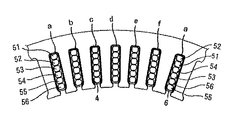
図3は、スロット内に複数対の導線が装着された状態を示す断面図である。同図に示したように、1対の第1導線51と第2導線52は、スペースを効率よく使うためにスロット4の深さ方向の内層側と外層側を交互に採るように所定のスロットピッチ(図では第1スロットの次に第7スロット)で装着される。他の対の第3導線53と第4導線54及び第5導線55と第6導線56も同様に内層側と外層側を交互に採るように所定のスロットピッチで装着され、コイルaを形成する。また、同様に、残る5相のコイルb、c、d、e、fの導線が所定のスロットピッチで装着される。ここでは、コイルa及びコイルdをU相、コイルb及びコイルeをV相、コイルc及びコイルfをW相とする。
FIG. 3 is a cross-sectional view showing a state in which a plurality of pairs of conducting wires are mounted in the slot. As shown in the figure, a pair of first
このように、長尺の導線を固定子鉄心の端面の外側で折り返して、所定スロットピッチでスロットにコイルを装着することによって、コイルエンドが整列された、いわゆる整列巻とすることができる。 In this way, a long conductive wire is folded back outside the end face of the stator core, and a coil is mounted in the slot at a predetermined slot pitch, whereby a so-called aligned winding in which the coil ends are aligned can be obtained.
図4は、この発明の実施の形態1における、コイルaの結線を説明するための模式図である。図4において、丸はスロット内に配置された導線(図2において、紙面の上下方向に直立する線)であり、丸を結ぶ実線は固定子鉄心の一方の端部のコイルエンドを示し、丸を結ぶ破線は固定子鉄心の他方の端部のコイルエンドを示し、縦方向に同一の位置にある丸は同一のスロットに装着されていることを示している。また、丸の上の数字は、コイルa1相について見た場合の装着スロットに対して、順に番号を付したものであり、図示していないが、横方向の丸と丸の間には他の5相の導線とスロットが存在し、スロット数は全部で96存在する。 FIG. 4 is a schematic diagram for explaining the connection of the coil a in the first embodiment of the present invention. In FIG. 4, circles are conductive wires arranged in the slots (in FIG. 2, lines standing up and down in the drawing), and a solid line connecting the circles indicates a coil end at one end of the stator core. The broken line connecting the two indicates the coil end of the other end of the stator core, and the circles at the same position in the vertical direction indicate that they are mounted in the same slot. In addition, the numbers above the circles are numbers assigned in order to the mounting slots when viewed with respect to the coil a1 phase, and although not shown, there are other numbers between the circles in the horizontal direction. There are five-phase conductors and slots, and there are a total of 96 slots.
図4に示したように、1つの相(U相)のコイルaは、第1導線51と第2導線52、第3導線53と第4導線54及び第5導線55と第6導線56の3対から構成され、これらの導線のうち、第1導線51、第3導線53及び第5導線55を、1番スロットと16番スロットの端末で直列に接続し、第1の導線51の8番スロットと9番スロットとの間のコイルエンドでリード線201及び202を配置して、3ターンのコイル107を構成する。
As shown in FIG. 4, one-phase (U-phase) coil a includes a
第2導線52、第4導線54及び第6導線56は、それぞれ1番スロットと16番スロットの端末で接続して、さらに、第2導線52の5番スロットと6番スロットとの間のコイルエンドでリード線203及びリード線204を配置し、第4導線54の7番スロットと8番スロットとの間のコイルエンドでリード線205及びリード線206を配置し、また、第6導線56の第3番スロットと第4番スロットとの間のコイルエンドでリード線207及びリード線208を配置し、さらに、第6導線56の第11番スロットと第12番スロットとの間のコイルエンドで、リード線209及びリード線210を配置している。
The second conducting
これらのリード線の配置により、リード線203からリード線204までの1ターンのコイル102と、リード線205からリード線206までの1ターンのコイル104とが形成される。また、第6配線56は2箇所からリード線を出すことによって、リード線208からリード線209までの0.5ターンのコイル109の組と、リード線210からリード線207までの0.5ターンのコイル110の組に分割される。
By arranging these lead wires, a one-
リード線208とリード線203とを接続することにより、コイル102とコイル109が直列接続され、1.5ターンのコイルが構成される。また、リード線210とリード線205を接続することにより、コイル104とコイル110が直列接続され、1.5ターンのコイルが構成される。
By connecting the
次に、リード線209とリード線207を接続部211に接続し、リード線204とリード線206を接続部212に接続することにより、2つの1.5ターンのコイルが並列に接続される。さらに、コイル107のリード線202を接続部212に接続することで、2本並列の1.5ターンのコイルと3ターンのコイルとが直列に接続され、4.5ターンのコイルが構成される。
Next, the
以上、1相の結線について説明したが、他の5相についても同様の結線を行い、2本並列の1.5ターンのコイルと3ターンのコイルとが直列に接続された4.5ターンのコイルを構成する。 The one-phase connection has been described above, but the same connection is made for the other five phases, and two 1.5-turn coils in parallel and three-turn coils are connected in series. Configure the coil.
4.5ターンのコイルの端末はリード線201と接続部211で構成され、リード線201と接続部211の内のいずれか一方を、他の2相の4.5ターンのコイルと接続することによって、例えば電気角が互いに60゜ずれた、図5に示すような、一対のY結線コイルや、図示していないが、例えば電気角が互いに60゜ずれた一対のΔ結線コイルを製作することができる。なお、図5において、V相及びW相もU相と同様のコイルの構成となっている。
The terminal of the 4.5-turn coil is composed of the
この実施の形態1では、第6導線56を2分割して0.5ターンの組を作ることによって、4.5ターンの非整数コイルを構成したが、第6導線56を4分割した組を並列に接続して0.25ターンのコイルを作ることによって、4.25ターンの非整数ターンのコイルを作製することもできる。また、例えば、第6導線56を分割し、分割した一部を比整数ターンの組とすることもできる。
In the first embodiment, a non-integer coil of 4.5 turns is formed by dividing the
また、実施の形態1では、第1導線51、第3導線53、第5導線55を直列接続して3ターンのコイルを作り、第2導線52と第6導線の内の0.5ターンの組とを直列に接続した1.5ターンのコイルと、第4導線54と第6導線の内の残りの0.5ターンの組とを直列に接続した1.5ターンのコイルとを並列に接続することによって1.5ターンのコイルを作り、この1.5ターンのコイルと、先の3ターンのコイルとを直列に接続することにより、4.5ターンのコイルを作製したが、図6に示すように、第3導線53と第5導線55と第6導線56の内の0.5ターンの組とを直列に接続して2.5ターンのコイルを作り、第2導線52と第4導線54と第6導線56の内の残りの0.5ターンの組とを直列に接続して2.5ターンのコイルを作り、この2つの2.5ターンのコイルを並列に接続し、この並列に接続した2.5ターンのコイルと第1導線51とを接続することによって、3.5ターンのコイルを構成することもできる。なお、図6において、V相及びW相もU相と同様のコイルの構成となっている。
In the first embodiment, the
また、図示しないが、第1導線51、第3導線53、第5導線55を直列接続した3ターンのコイルをΔ結線し、Δ結線の接続部に、第2導線52と分割した第6導線56による1.5ターンの組と、第4導線54と分割した残りの第6導線5による1.5ターンの組とを並列接続したコイルを結線してもよい。
In addition, although not shown in the figure, a sixth conductor obtained by delta-connecting a three-turn coil in which the
また、1スロット内に6本の導線があり、1相当たりのスロット数は16個あるので、分割できる位置(全スロット内の導体数の合計)は6×16=96個あり、分割位置を変えることによって、96個の内の任意数の導体m個を組みとして複数組構成し、この複数組を並列接続することによって、m/Sターン(Sは1相当たりのスロット数)の非整数ターンコイルが得られる。例えば、8個の導体を組として、2組を並列接続した場合、m=8でS=16であるので、m/S=0.5となり、0.5ターンのコイルを含む非整数ターンのコイルが得られる。 In addition, since there are six conductors in one slot and there are 16 slots per phase, there are 6 × 16 = 96 positions that can be divided (total number of conductors in all slots). By changing, m sets of any number of conductors out of 96 are set as a set, and by connecting these sets in parallel, m / S turn (S is the number of slots per phase) is a non-integer number A turn coil is obtained. For example, when two conductors are connected in parallel with eight conductors as a set, since m = 8 and S = 16, m / S = 0.5, and a non-integer turn including a coil of 0.5 turns A coil is obtained.
また、1相のスロット数が16で、スロット内に3対の導体(6本)が装着された例を示したが、このスロット数及び導線数に限られるものではない。
スロットに入っている導線数をn(整数)とし、1相当たりのスロット数をSとすると、分割できる位置(全スロット内の導体数の合計)は(S×n)となる。これらの(S×n)個の導体の内の任意のm個の導体を組として複数組構成し、この複数組を並列接続することによって、m/Sターンのコイルを含む非整数ターンのコイルを作製することができる。
Moreover, although the number of slots for one phase is 16 and three pairs of conductors (six wires) are mounted in the slot, the number of slots and the number of conductors are not limited.
Assuming that the number of conducting wires in the slot is n (integer) and the number of slots per phase is S, the position that can be divided (the total number of conductors in all slots) is (S × n). A coil of non-integer turns including a coil of m / S turns by forming a plurality of sets of arbitrary m conductors of these (S × n) conductors and connecting the plurality of sets in parallel. Can be produced.
また、導線はコイルエンド部で連続接続されているので、周方向で導線を分割して、複数組を形成し、この複数組を並列接続することによって、リード線及びリード線の接続箇所を少なくすることができる。 In addition, since the conducting wires are continuously connected at the coil end portion, the conducting wires are divided in the circumferential direction to form a plurality of sets, and the plurality of sets are connected in parallel, thereby reducing the number of connecting portions of the lead wires and the lead wires. can do.
また、非整数ターンのコイルの数と整数ターンのコイルの数との比が変わると磁気特性が変わるが、全てのスロットにおいて、非整数ターンのコイル及び整数ターンのコイルの数を同じにすることによって、固定子1の全周における磁気特性を均一にすることができるので、回転機の騒音を低減することができる。
In addition, the magnetic characteristics change when the ratio of the number of non-integer turns to the number of coils of integer turns changes, but the number of non-integer turns and integer turns must be the same in all slots. Thus, the magnetic characteristics of the entire circumference of the
また、整列巻の場合は、スロットによって、導線数を変えてターン数を変えることができないが、この実施の形態によれば、整列巻の場合にも容易に非整数ターン数のコイルが得られるので、この実施の形態は特に整列巻の場合に有効となる。 In the case of aligned winding, the number of turns cannot be changed by changing the number of conductors depending on the slot. However, according to this embodiment, a coil having a non-integer number of turns can be easily obtained even in the case of aligned winding. Therefore, this embodiment is particularly effective in the case of aligned winding.
実施の形態2.
上記実施の形態1に示したような、並列接続されたコイルと並列接続されていないコイルとがともに存在する場合、1つのスロット内にも、並列接続されたコイルと並列接続でないコイルとがともに存在することになる。
When both the coil connected in parallel and the coil not connected in parallel exist as shown in the first embodiment, both the coil connected in parallel and the coil not connected in parallel are also present in one slot. Will exist.
図7は、1つのスロット内に並列接続されたコイルの導体と並列接続でないコイルの導体とがともに存在する場合の漏れ磁束の状態を説明する図である。 FIG. 7 is a diagram for explaining the state of magnetic flux leakage when both the coil conductors connected in parallel and the coil conductors not connected in parallel exist in one slot.
図7に示したように、スロット4内の導体に電流が流れると、この電流の大きさに応じてスロット4内に漏れ磁束が発生する。この漏れ磁束は、出力に関係なく発生するために鉄損等となり、モータの出力特性に悪影響を及ぼす。
As shown in FIG. 7, when a current flows through a conductor in the
図7では、並列接続されたコイル50aの導体をスロット4の内層側の底部に寄せて配置している。この場合、並列接続されたコイル50aの導体に流れる電流は、並列接続されていないコイル50bの導体に流れる電流よりも小さいので、並列接続されたコイル50aの導体の漏れ磁束は、並列接続されていないコイル50bの導体の漏れ磁束より小さくなる。また、スロット4の内層側の底部の方がスロット4の外層側の開口部よりも漏れインダクタンスが大きくなる。従って、漏れインダクタンスが大きくなるスロット4の内層側の底部に、電流が小さい並列接続されたコイル50aの導体を配置することによって、全体の漏れ磁束量が低減される。
In FIG. 7, the conductors of the
さらに、回転子が発生する磁束は、スロット4の開口部から入り、コイルの導体と鎖交してモータ出力となるが、スロット4内のコイルの導体と同様に、スロット4内で漏れ磁束を発生し、回転子側から最も遠いスロット4の内層側の底部における鎖交磁束よりもスロット4の開口部近辺における鎖交磁束の方が多くなる。従って、回転子の磁束を有効にコイルの導体に鎖交させるためには、並列接続されていないコイル50bの導体をスロット4の開口部近辺に配置することが望ましい。
Further, the magnetic flux generated by the rotor enters from the opening of the
図8は、スロット内でのコイルの導体の配置例を示す図である。図8(a)は、並列接続したコイル50aをスロットの底部に配置している。図8(b)は、前述のように、スロットのスペースを効率よく使うためにスロット4の底部の内層側と外層側を交互に採るように導線を配置した場合を示している。
FIG. 8 is a diagram illustrating an arrangement example of the conductors of the coil in the slot. In FIG. 8A, the
以上のように、並列接続されたコイル50aの導体をスロット4の内層側の底部に配置し、並列接続されていないコイル50bの導体をスロット4の開口部近辺に配置することにより、モータの出力特性を向上することができる。
As described above, by arranging the conductor of the
また、並列接続されたコイル50aに流れる電流は、並列接続されていないコイル50bに流れる電流よりも小さいので、コイル50aの導体の断面積を、コイル50bの導体の断面積より小さくすることができる。コイル50aの導体の断面積を小さくした場合は、スロット内のコイル50bの導体の断面積を、コイル50aの導体の断面積を小さくした分、大きくして抵抗を小さくすることができるので、スロット内に同じ断面積のコイル50bの導体を装着した場合よりも、コイル全体の発熱量を小さくすることができる。
Further, since the current flowing through the
実施の形態3.
図9は、図4に示した結線図のリード線接続部に、スイッチを設けた例を示す結線図である。
FIG. 9 is a connection diagram illustrating an example in which a switch is provided in the lead wire connection portion of the connection diagram illustrated in FIG. 4.
図9(a)では、スイッチ501及びスイッチ502によって、図4に示した結線状態と同じに構成され、第6配線56が0.5ターンに分断され、4.5ターンのコイルが構成されている。一方、図9(b)では、スイッチ501及びスイッチ502をスライドさせて、第6配線56の分断部を接続して1ターンのコイルを構成するとともに、第2配線52と第4配線54とを並列接続して1ターンのコイルを構成し、第1配線51、第3配線53及び第5配線55からなる3ターンのコイルと、第2配線52と第4配線54とを並列接続した1ターンのコイルと、第6配線56の1ターンのコイルとを直列に接続した5ターンのコイルを構成している。すなわち、4.5ターンのコイルの構成と5ターンのコイルの構成とを、スイッチ501及びスイッチ502によって切り替えることができるものである。
In FIG. 9A, the
このように、スイッチを設けて、並列接続及び直列接続を切り替えることにより、コイルのターン数を切り替えることができ、例えば、エンジンの回転数が低速の場合には、コイルのターン数を5ターンとし、エンジンの回転数が高速の場合には、コイルのターン数を4.5ターンとする等のように、エンジンの回転数に合わせて、モータの出力特性を適正な状態にすることができる。 Thus, by providing a switch and switching between parallel connection and series connection, the number of turns of the coil can be switched. For example, when the engine speed is low, the number of turns of the coil is 5 turns. When the rotational speed of the engine is high, the output characteristics of the motor can be brought into an appropriate state in accordance with the rotational speed of the engine, such as setting the number of turns of the coil to 4.5 turns.
この発明に係る回転電機の固定子は、例えば、車両用交流発電機等の固定子に利用することができる。 The stator of the rotating electrical machine according to the present invention can be used, for example, for a stator such as a vehicle AC generator.
1 固定子、2 固定子鉄心、3,201〜210 リード線、4 スロット、
5,107,109〜110 コイル、5a コイルエンド、
50a 並列接続されたコイル、50b 並列接続でないコイル、51 第1配線、
52 第2配線、53 第3配線、504 第4配線、55 第5配線、
56 第6配線、211,212 接続部、501,502 スイッチ。
1 Stator, 2 Stator core, 3, 201-210 Lead wire, 4 slots,
5, 107, 109 to 110 coil, 5a coil end,
50a Coil connected in parallel, 50b Coil not connected in parallel, 51 First wiring,
52 2nd wiring, 53 3rd wiring, 504 4th wiring, 55 5th wiring,
56 6th wiring, 211,212 connection part, 501,502 switch.
Claims (7)
上記各相のコイルは、n本の導線を上記固定子鉄心の端面の外側で折り返して所定スロットピッチで、上記スロットに装着してなり、
上記各相におけるスロット数をS個とし、上記各相において、全スロット内の(S・n)個の導体の内からm個を選択した組を複数組構成し、上記複数組を並列接続することにより、非整数のm/Sターンのコイルを構成し、選択されなかった導体からなる整数ターンのコイルと組み合わせて非整数ターンのコイルを構成したことを特徴とする回転電機の固定子。 A stator core having a plurality of slots extending in the axial direction of a circular laminated body in which thin steel plates are laminated and provided at a predetermined pitch in the circumferential direction, and coils constituting U, V, and W phases. ,
The coils of the respective phases are formed by folding n conductors outside the end face of the stator core and attaching them to the slots at a predetermined slot pitch.
The number of slots in each phase is S, and in each phase, a plurality of sets are selected by selecting m of (S · n) conductors in all slots, and the plurality of sets are connected in parallel. Thus, a non-integer m / S-turn coil is formed, and a non-integer-turn coil is formed in combination with an integer-turn coil made of an unselected conductor.
The stator for a rotating electrical machine according to any one of claims 1 to 6, further comprising a switch for switching the number of turns of the non-integer m / S turn coil and the integer turn coil.
Priority Applications (2)
| Application Number | Priority Date | Filing Date | Title |
|---|---|---|---|
| JP2004093973A JP4146379B2 (en) | 2004-03-29 | 2004-03-29 | Rotating electric machine stator |
| US11/083,096 US7009320B2 (en) | 2004-03-29 | 2005-03-18 | Stator of electric rotating machine |
Applications Claiming Priority (1)
| Application Number | Priority Date | Filing Date | Title |
|---|---|---|---|
| JP2004093973A JP4146379B2 (en) | 2004-03-29 | 2004-03-29 | Rotating electric machine stator |
Publications (2)
| Publication Number | Publication Date |
|---|---|
| JP2005287109A true JP2005287109A (en) | 2005-10-13 |
| JP4146379B2 JP4146379B2 (en) | 2008-09-10 |
Family
ID=34988950
Family Applications (1)
| Application Number | Title | Priority Date | Filing Date |
|---|---|---|---|
| JP2004093973A Expired - Fee Related JP4146379B2 (en) | 2004-03-29 | 2004-03-29 | Rotating electric machine stator |
Country Status (2)
| Country | Link |
|---|---|
| US (1) | US7009320B2 (en) |
| JP (1) | JP4146379B2 (en) |
Cited By (11)
| Publication number | Priority date | Publication date | Assignee | Title |
|---|---|---|---|---|
| JPWO2007088598A1 (en) * | 2006-02-01 | 2009-06-25 | 三菱電機株式会社 | Rotating electric machine |
| JP2011097769A (en) * | 2009-10-30 | 2011-05-12 | Denso Corp | Stator for dynamo-electric machine and dynamo-electric machine |
| WO2011148527A1 (en) * | 2010-05-28 | 2011-12-01 | 三菱電機株式会社 | Rotating electric machine |
| JP2013150500A (en) * | 2012-01-23 | 2013-08-01 | Mitsubishi Electric Corp | Rotary electric machine |
| JP2014090615A (en) * | 2012-10-31 | 2014-05-15 | Aisin Seiki Co Ltd | Wave winding for three-phase rotary electric machine |
| JP2014103850A (en) * | 2014-03-13 | 2014-06-05 | Mitsubishi Electric Corp | Rotary electric machine |
| JP2014143828A (en) * | 2013-01-23 | 2014-08-07 | Aisin Seiki Co Ltd | Wave winding for rotary electric machine |
| US9130431B2 (en) | 2010-12-13 | 2015-09-08 | Denso Corporation | Stator for rotary electrical machine |
| JP2016012981A (en) * | 2014-06-27 | 2016-01-21 | 株式会社デンソー | Stator for rotary electric machine |
| WO2016190033A1 (en) * | 2015-05-22 | 2016-12-01 | 日立オートモティブシステムズ株式会社 | Rotary electric device stator |
| JP2018093714A (en) * | 2016-11-30 | 2018-06-14 | ドクター エンジニール ハー ツェー エフ ポルシェ アクチエンゲゼルシャフトDr. Ing. h.c. F. Porsche Aktiengesellschaft | Stator of electric machine or bar winding structure of rotator |
Families Citing this family (15)
| Publication number | Priority date | Publication date | Assignee | Title |
|---|---|---|---|---|
| DE10137270A1 (en) * | 2001-07-31 | 2003-02-20 | Aloys Wobben | Wind energy installation has a ring generator with a stator having grooves spaced at intervals on an internal or external periphery for receiving a stator winding. |
| EP1653587B1 (en) * | 2004-10-29 | 2013-06-26 | Hitachi, Ltd. | Rotating electrical machine and manufacturing method thereof |
| US7075206B1 (en) * | 2005-02-07 | 2006-07-11 | Visteon Global Technologies, Inc. | Vehicle alternator stator winding having dual slot configuration |
| KR100894758B1 (en) * | 2005-11-01 | 2009-04-24 | 파나소닉 주식회사 | Motor and method of manufacturing stator used therefor |
| FR2896350B1 (en) * | 2006-01-16 | 2008-02-29 | Valeo Equip Electr Moteur | METHOD FOR REALIZING THE WINDING OF A STATOR OF ROTATING ELECTRIC MACHINE, AND STATOR OBTAINED THEREBY |
| JP4715934B2 (en) * | 2009-02-20 | 2011-07-06 | 株式会社デンソー | 5-phase motor |
| JP5471867B2 (en) * | 2009-07-17 | 2014-04-16 | 株式会社デンソー | Rotating electric machine stator |
| JP5478987B2 (en) * | 2009-08-21 | 2014-04-23 | 株式会社マキタ | Electric tool |
| US8531078B2 (en) | 2011-05-26 | 2013-09-10 | Hamilton Sundstrand Corporation | Interspersed multi-layer concentric wound stator |
| US11735968B2 (en) | 2014-12-26 | 2023-08-22 | Hitachi Astemo, Ltd. | Rotary electric machine and vehicle provided with the same |
| CN107112838B (en) * | 2014-12-26 | 2019-09-03 | 日立汽车系统株式会社 | Rotating electric machine and the vehicle for being equipped with the rotating electric machine |
| JP6235504B2 (en) * | 2015-02-17 | 2017-11-22 | ファナック株式会社 | Radial gap type motor with distributed winding and winding arrangement method thereof |
| CN107638081B (en) * | 2016-07-22 | 2020-05-01 | 佛山市顺德区美的电热电器制造有限公司 | Coil panel and cooking appliance |
| HUE063881T2 (en) * | 2017-05-21 | 2024-02-28 | Alejandro Bosco | Electric motor and winding method |
| DE102019126338A1 (en) * | 2019-09-30 | 2021-04-01 | Valeo Siemens Eautomotive Germany Gmbh | Stator with pins for an electrical machine |
Family Cites Families (11)
| Publication number | Priority date | Publication date | Assignee | Title |
|---|---|---|---|---|
| US3408517A (en) * | 1966-02-23 | 1968-10-29 | Gen Electric | Multiple circuit winding patterns for polyphase dynamoelectric machines |
| US3652688A (en) * | 1968-12-30 | 1972-03-28 | Cities Service Co | Halogenation of unsaturated hydrocarbons |
| US3652888A (en) * | 1971-03-18 | 1972-03-28 | Gen Electric | Two pole, 45 slot, three circuit dynamoelectric machine winding pattern |
| DE2629642C3 (en) * | 1976-07-01 | 1979-08-30 | Siemens Ag, 1000 Berlin Und 8000 Muenchen | Pole-changing three-phase winding |
| US4409507A (en) * | 1982-06-28 | 1983-10-11 | Westinghouse Electric Corp. | Dynamoelectric machines for multiples of three phases with unbalanced fractional-slot windings |
| DE9212889U1 (en) | 1992-09-24 | 1994-01-27 | Siemens Ag | Winding arrangement for a multi-phase electrical machine |
| US5898251A (en) | 1995-08-18 | 1999-04-27 | Kabushiki Kaisha Toshiba | Method of making armature winding of double-layer concentric-wound or lap-winding type for dynamoelectric machine |
| JP3155534B1 (en) | 2000-01-20 | 2001-04-09 | 三菱電機株式会社 | Alternator stator |
| JP3633494B2 (en) | 2001-02-20 | 2005-03-30 | 株式会社デンソー | Rotating electric machine |
| JP2002291187A (en) | 2001-03-26 | 2002-10-04 | Matsushita Electric Ind Co Ltd | Wire winding method for motor and motor using the winding |
| US6570290B2 (en) * | 2001-06-29 | 2003-05-27 | General Electric Company | Single layer interspersed concentric stator winding apparatus and method |
-
2004
- 2004-03-29 JP JP2004093973A patent/JP4146379B2/en not_active Expired - Fee Related
-
2005
- 2005-03-18 US US11/083,096 patent/US7009320B2/en active Active
Cited By (16)
| Publication number | Priority date | Publication date | Assignee | Title |
|---|---|---|---|---|
| JPWO2007088598A1 (en) * | 2006-02-01 | 2009-06-25 | 三菱電機株式会社 | Rotating electric machine |
| US8736131B2 (en) | 2006-02-01 | 2014-05-27 | Mitsubishi Electric Corporation | Dynamoelectric machine with noise reduction |
| JP2011097769A (en) * | 2009-10-30 | 2011-05-12 | Denso Corp | Stator for dynamo-electric machine and dynamo-electric machine |
| WO2011148527A1 (en) * | 2010-05-28 | 2011-12-01 | 三菱電機株式会社 | Rotating electric machine |
| US9130431B2 (en) | 2010-12-13 | 2015-09-08 | Denso Corporation | Stator for rotary electrical machine |
| JP2013150500A (en) * | 2012-01-23 | 2013-08-01 | Mitsubishi Electric Corp | Rotary electric machine |
| JP2014090615A (en) * | 2012-10-31 | 2014-05-15 | Aisin Seiki Co Ltd | Wave winding for three-phase rotary electric machine |
| JP2014143828A (en) * | 2013-01-23 | 2014-08-07 | Aisin Seiki Co Ltd | Wave winding for rotary electric machine |
| JP2014103850A (en) * | 2014-03-13 | 2014-06-05 | Mitsubishi Electric Corp | Rotary electric machine |
| JP2016012981A (en) * | 2014-06-27 | 2016-01-21 | 株式会社デンソー | Stator for rotary electric machine |
| WO2016190033A1 (en) * | 2015-05-22 | 2016-12-01 | 日立オートモティブシステムズ株式会社 | Rotary electric device stator |
| JP2016220434A (en) * | 2015-05-22 | 2016-12-22 | 日立オートモティブシステムズ株式会社 | Stator of rotary electric machine |
| CN107615621A (en) * | 2015-05-22 | 2018-01-19 | 日立汽车系统株式会社 | The stator of electric rotating machine |
| CN107615621B (en) * | 2015-05-22 | 2020-09-22 | 日立汽车系统株式会社 | Stator of rotating electric machine |
| JP2018093714A (en) * | 2016-11-30 | 2018-06-14 | ドクター エンジニール ハー ツェー エフ ポルシェ アクチエンゲゼルシャフトDr. Ing. h.c. F. Porsche Aktiengesellschaft | Stator of electric machine or bar winding structure of rotator |
| US10637314B2 (en) | 2016-11-30 | 2020-04-28 | Dr. Ing. H.C. F. Porsche Aktiengesellschaft | Bar winding arrangement of a stator or a rotor of an electric machine |
Also Published As
| Publication number | Publication date |
|---|---|
| US7009320B2 (en) | 2006-03-07 |
| JP4146379B2 (en) | 2008-09-10 |
| US20050212372A1 (en) | 2005-09-29 |
Similar Documents
| Publication | Publication Date | Title |
|---|---|---|
| JP4146379B2 (en) | Rotating electric machine stator | |
| JP6609373B2 (en) | Rotating electric machine | |
| CN109565203B (en) | Electric machine comprising a stator winding with upper and lower end rings | |
| KR101122967B1 (en) | Electrical machine having a stator winding with a plurality of filars | |
| JP5858145B2 (en) | coil | |
| JP6623961B2 (en) | Rotating machine stator | |
| JP6707860B2 (en) | Rotary electric machine and method of manufacturing the same | |
| WO2006065988A2 (en) | Motor winding | |
| JP5502913B2 (en) | Rotating electric machine | |
| JP6954374B2 (en) | Stator | |
| JP4349292B2 (en) | Rotating electric machine for vehicles having concentrated winding type stator | |
| JP5566541B1 (en) | Rotating electric machine | |
| JP2005312278A (en) | Concentrated winding stator coil of rotary electric machine | |
| MX2007009295A (en) | Distributed coil stator for external rotor three phase electric motors. | |
| CN116195172A (en) | Stator and motor | |
| JP2017158256A (en) | Wound structure of rotary electric machine stator | |
| CN110556956B (en) | Stator assembly and motor with same | |
| JP5748878B2 (en) | Rotating electric machine | |
| JP2011182524A (en) | Armature for rotary electric machine | |
| JP4265973B2 (en) | Rotating electric machine stator | |
| JP5163255B2 (en) | Rotating electric machine stator | |
| JP2015154708A (en) | rotary electric machine stator | |
| WO2023210686A1 (en) | Stator and motor | |
| JP2023163597A (en) | stator and motor | |
| CN114448130A (en) | Stator and motor |
Legal Events
| Date | Code | Title | Description |
|---|---|---|---|
| A621 | Written request for application examination |
Free format text: JAPANESE INTERMEDIATE CODE: A621 Effective date: 20051121 |
|
| A977 | Report on retrieval |
Free format text: JAPANESE INTERMEDIATE CODE: A971007 Effective date: 20070919 |
|
| A131 | Notification of reasons for refusal |
Free format text: JAPANESE INTERMEDIATE CODE: A131 Effective date: 20070925 |
|
| A521 | Request for written amendment filed |
Free format text: JAPANESE INTERMEDIATE CODE: A523 Effective date: 20071126 |
|
| A131 | Notification of reasons for refusal |
Free format text: JAPANESE INTERMEDIATE CODE: A131 Effective date: 20080325 |
|
| A521 | Request for written amendment filed |
Free format text: JAPANESE INTERMEDIATE CODE: A523 Effective date: 20080523 |
|
| TRDD | Decision of grant or rejection written | ||
| A01 | Written decision to grant a patent or to grant a registration (utility model) |
Free format text: JAPANESE INTERMEDIATE CODE: A01 Effective date: 20080617 |
|
| A01 | Written decision to grant a patent or to grant a registration (utility model) |
Free format text: JAPANESE INTERMEDIATE CODE: A01 |
|
| A61 | First payment of annual fees (during grant procedure) |
Free format text: JAPANESE INTERMEDIATE CODE: A61 Effective date: 20080619 |
|
| R150 | Certificate of patent or registration of utility model |
Free format text: JAPANESE INTERMEDIATE CODE: R150 Ref document number: 4146379 Country of ref document: JP Free format text: JAPANESE INTERMEDIATE CODE: R150 |
|
| FPAY | Renewal fee payment (event date is renewal date of database) |
Free format text: PAYMENT UNTIL: 20110627 Year of fee payment: 3 |
|
| FPAY | Renewal fee payment (event date is renewal date of database) |
Free format text: PAYMENT UNTIL: 20120627 Year of fee payment: 4 |
|
| FPAY | Renewal fee payment (event date is renewal date of database) |
Free format text: PAYMENT UNTIL: 20130627 Year of fee payment: 5 |
|
| R250 | Receipt of annual fees |
Free format text: JAPANESE INTERMEDIATE CODE: R250 |
|
| R250 | Receipt of annual fees |
Free format text: JAPANESE INTERMEDIATE CODE: R250 |
|
| R250 | Receipt of annual fees |
Free format text: JAPANESE INTERMEDIATE CODE: R250 |
|
| LAPS | Cancellation because of no payment of annual fees |