JP2005286419A - Image pickup device - Google Patents
Image pickup device Download PDFInfo
- Publication number
- JP2005286419A JP2005286419A JP2004093542A JP2004093542A JP2005286419A JP 2005286419 A JP2005286419 A JP 2005286419A JP 2004093542 A JP2004093542 A JP 2004093542A JP 2004093542 A JP2004093542 A JP 2004093542A JP 2005286419 A JP2005286419 A JP 2005286419A
- Authority
- JP
- Japan
- Prior art keywords
- subject
- image
- imaging
- information
- unit
- Prior art date
- Legal status (The legal status is an assumption and is not a legal conclusion. Google has not performed a legal analysis and makes no representation as to the accuracy of the status listed.)
- Pending
Links
Images


Landscapes
- Details Of Cameras Including Film Mechanisms (AREA)
- Indication In Cameras, And Counting Of Exposures (AREA)
- Studio Devices (AREA)
Abstract
Description
本発明は、特定の被写体を撮影する撮影方法およびその装置に関する。特に送受信機を使用して被写体の位置等を検出する手段を有する撮像装置に関する。 The present invention relates to a photographing method and apparatus for photographing a specific subject. In particular, the present invention relates to an imaging apparatus having means for detecting the position of a subject using a transceiver.
従来は、例えば特許文献1では、ゴルフ場に複数のカメラを設置し、IDタグを持ったプレーヤがプレーを進めていくと、プレーヤの位置を複数の受信機で検出し、近傍のカメラが選択され、ズーミングを行いショットを撮影するということが提案されている。
Conventionally, in
また、特許文献2は、赤外線発信機を特定被写体に携帯させ、受信機を備えたビデオカメラで撮影することにより、同じ服装をした複数の人間の中から特定人を簡単に撮影できるという提案が記載されている。 Patent Document 2 proposes that a specific person can be easily photographed from a plurality of people wearing the same clothes by carrying an infrared transmitter with a specific subject and photographing with a video camera equipped with a receiver. Has been described.
また、特許文献3では、複数のカメラから距離が近い等の条件から最適なカメラを選択、表示する映像切替えシステムが提案されている。
しかしながら、従来例は被写体の位置を検出し、撮像装置に位置を知らせる、あるいは固定された複数の撮像装置から適当なもので撮影する、というものであって、被写体の向きに関しては特に考慮されていなかった。そのため被写体の位置を特定しても必ずしも好ましい撮影(正面、顔を撮る等)ができないという課題があった。 However, in the conventional example, the position of the subject is detected, the position is notified to the imaging device, or shooting is performed with an appropriate one from a plurality of fixed imaging devices, and the orientation of the subject is particularly considered. There wasn't. Therefore, there is a problem that even if the position of the subject is specified, it is not always possible to perform preferable shooting (front, face, etc.).
本発明は、上記課題を鑑みてなされたもので、複数の方向から同一被写体を撮影し、被写体が人である場合その正面又は顔が向いている方のカメラの映像を出力することが可能な撮像装置を提供することを目的とするものである。 The present invention has been made in view of the above problems, and is capable of shooting the same subject from a plurality of directions and outputting the image of the camera facing the front or face when the subject is a person. An object of the present invention is to provide an imaging device.
請求項1記載の発明による撮像装置は、
異なる位置に設けられ、異なる方向に向けられた複数の撮像手段と、
前記撮像手段により撮影される被写体の位置情報および方向情報を発信する位置方向情報発信手段と、
前記位置方向情報発信手段からの位置情報と方向情報を受信する受信手段と、
前記受信手段により受信された被写体の位置情報と方向情報から、被写体の位置および方向を算出する被写体位置方向算出手段とを有し、
前記被写体位置方向算出手段により算出された被写体の位置及び方向から、被写体を撮影する撮像手段を前記複数の撮像手段から選択し、被写体の画像を撮影することを特徴とする。
An imaging apparatus according to the invention of
A plurality of imaging means provided at different positions and oriented in different directions;
Position and direction information transmitting means for transmitting position information and direction information of a subject imaged by the imaging means;
Receiving means for receiving position information and direction information from the position / direction information transmitting means;
Subject position / direction calculation means for calculating the position and direction of the subject from the position information and direction information of the subject received by the receiving means;
From the position and direction of the subject calculated by the subject position / direction calculating means, an imaging means for photographing the subject is selected from the plurality of imaging means, and an image of the subject is photographed.
請求項1記載の発明では、被写体に発信機を携帯させ、発信機と受信機の相対位置関係により被写体の位置と向いている方向を検出し、違う方向から同一被写体を撮像する複数の撮像手段の中から最適な撮像手段を選択することで、常時好ましい撮影(例えば、正面、顔を撮る等)が可能になる。 According to the first aspect of the present invention, a plurality of image pickup means for picking up the same subject from different directions by detecting the direction facing the position of the subject based on the relative positional relationship between the transmitter and the receiver by carrying the transmitter with the subject. By selecting an optimal imaging means from among the above, it is possible to always perform preferable photography (for example, taking a front view, a face, etc.).
請求項12記載の発明は、請求項1の撮像装置において、
前記複数の撮像手段から選択された撮像手段により撮影された被写体の画像の一部を、前記被写体位置方向算出手段の算出結果に基づき被写体を含むように切出す画像切出し手段と、
この画像切出し手段により切出された画像を表示する表示手段と、
前記画像切出し手段により切出された画像を表示手段の解像度に合わせて解像度変換する解像度変換手段と、を有することを特徴とする。
The invention according to
Image cutout means for cutting out a part of the image of the subject imaged by the imaging means selected from the plurality of imaging means so as to include the subject based on the calculation result of the subject position direction calculation means;
Display means for displaying the image cut out by the image cutting means;
Resolution conversion means for converting the resolution of the image cut out by the image cutout means in accordance with the resolution of the display means.
請求項12記載の発明では、請求項1の構成に更に画像切出し手段を設け、最適な撮像手段の画像の一部を切出すことにより、被写体のアップ画像を撮影することが可能になる。 According to the twelfth aspect of the present invention, it is possible to capture an up image of the subject by further providing an image cutting means in the configuration of the first aspect and cutting out a part of the image of the optimum image pickup means.
画像切出し部分の検出は、被写体の位置情報からカメラ撮影位置情報を算出して検出する。切出しサイズはユーザーが任意に設定しても、発信機の周囲数mを切出す等事前に決定してもよい。 The image cut-out portion is detected by calculating camera shooting position information from the position information of the subject. The cutting size may be arbitrarily set by the user, or may be determined in advance, such as cutting out a number m around the transmitter.
請求項15記載の発明は、請求項12の撮像装置において、
前記撮像手段は複数の画素を有する撮像素子を有しており、
前記複数の撮像手段から選択された撮像手段により撮影された被写体の画像の一部を、前記被写体位置方向算出手段の算出結果に基づき被写体を含むように切出す位置を指示する切出し位置指示手段と、
前記画切出し位置指示手段からの切出し位置指示に基づき、前記撮像素子内の切出す領域を指定する切出し領域指定手段とをさらに有しており、
この切出し領域指定手段により前記撮像素子により撮影された被写体像を切出すことを特徴とする。
The invention according to
The imaging means has an imaging device having a plurality of pixels,
A cutout position instruction means for instructing a position to cut out a part of an image of a subject imaged by the image pickup means selected from the plurality of image pickup means so as to include a subject based on a calculation result of the subject position direction calculation means; ,
Based on a cutout position instruction from the image cutout position instruction means, further comprising a cutout area designation means for designating a cutout area in the image sensor,
A subject image photographed by the image sensor is cut out by the cut-out area designating means.
請求項15記載の発明では、被写体切出し手段を各撮像手段の撮像素子で行うことを特徴としている。標準動画像の画素数(例えばHDTVは200万画素)より多画素の撮像素子(例えば800万画素)で撮影を行い、その画像の一部を切出して被写体をアップで表示することが可能になる。切出し画素数を標準動画像の画素数に合わせて撮像手段から出力してもよいし、或いは、任意の画素数で切出して、後段にスキャンコンバータを設け、そこで標準動画像の画素数に変換してもよい。
The invention described in
請求項16記載の発明による撮像装置は、
フィールド上の異なる位置及び方向に設けられ、被写体を含む画像情報を得る複数の撮像手段と、
フィールド上に存在する前記被写体の位置情報および方向情報を発信する被写体位置方向発信手段と、
前記被写体位置方向発信手段からの位置情報と方向情報を受信する受信手段と、
前記受信手段により受信された被写体の位置情報と方向情報から、フィールド上の被写体の位置および方向を算出する被写体位置方向算出手段と、
前記被写体位置方向算出手段にて算出されたフィールド上の被写体の位置及び方向を、前記撮像手段が撮像する方向及び/又は画角を基準とするカメラ座標、或いは撮像手段が撮像する撮像素子平面座標に変換する座標変換手段とを有し、
この座標変換手段により変換された被写体の座標および向きから、被写体を撮影する撮像手段を前記複数の撮像手段から選択し、被写体の画像を撮影することを特徴とする。
An imaging device according to the invention of
A plurality of imaging means provided at different positions and directions on the field and obtaining image information including a subject;
Subject position direction transmitting means for transmitting position information and direction information of the subject existing on the field;
Receiving means for receiving position information and direction information from the subject position direction transmitting means;
Subject position / direction calculation means for calculating the position and direction of the subject on the field from the subject position information and direction information received by the receiving means;
The position and direction of the subject on the field calculated by the subject position / direction calculation means, the camera coordinates based on the direction and / or angle of view taken by the imaging means, or the imaging element plane coordinates taken by the imaging means Coordinate conversion means for converting to
From the coordinates and orientation of the subject converted by the coordinate conversion means, an imaging means for photographing the subject is selected from the plurality of imaging means, and an image of the subject is photographed.
請求項16記載の発明では、発信・受信装置で得られた被写体の位置及び向きの情報をカメラ座標或いは撮像素子平面座標に変換することで、被写体を撮影する撮像手段を選択し、最適な被写体の画像の切出し撮影を行うものである。 According to the sixteenth aspect of the present invention, the information on the position and orientation of the subject obtained by the transmission / reception device is converted into camera coordinates or imaging element plane coordinates, so that an imaging means for photographing the subject is selected and the optimum subject is selected. The image is cut out and photographed.
本発明の撮像装置によれば、被写体に装着した発信機と受像機との関係により被写体の向きを検出し、複数の方向から同一被写体を撮影し、被写体が人である場合その正面又は顔が向いている方のカメラの映像を出力することが可能となる。 According to the imaging apparatus of the present invention, the orientation of the subject is detected based on the relationship between the transmitter and the receiver attached to the subject, the same subject is photographed from a plurality of directions, and when the subject is a person, the front or face is detected. It is possible to output the video of the camera that is facing.
発明の実施の形態について図面を参照して説明する。 Embodiments of the invention will be described with reference to the drawings.
図1は本発明の実施例1に係る撮像装置のブロック図である。
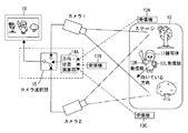
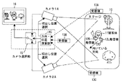
図1に示す撮像装置は、ステージ10上の被写体11の右肩と左肩に装着された周波数が違う位置方向情報発信手段としての複数(図では2つ)の無線発信機12R,12Lと、ステージ10の3方向に位置する受信手段としての無線受信機13A,13B,13Cと、2台の発信機12R,12Lの信号の時間差あるいは強弱比から被写体11の向きと位置を演算する被写体位置方向算出手段である方向・位置演算部14と、異なる方向から被写体11を撮影する撮像手段としての2台のカメラ1,2(2台のカメラは垂直同期している方が好ましい)と、2台のカメラ1,2の出力を選択する撮像手段選択部であるカメラ選択部15と、選択された画像を表示する表示手段としてのモニタ16とを備えて構成されている。撮像手段としてのカメラ1,2にはそれぞれ撮像素子を含んでおり、各カメラは被写体を光学系によって結像した後に撮像素子で撮像し被写体を含んだ画像情報を取得する機能を有するものである。
FIG. 1 is a block diagram of an imaging apparatus according to
The imaging apparatus shown in FIG. 1 includes a plurality of (two in the figure)
次に、図1の作用について説明する。
2台のカメラ1,2で異なる方向からステージ10上の被写体11を撮影する。ステージ10周囲にはステージ上の被写体11に取り付けた発信機12R,12Lからの電波を受信可能な3台の無線受信機13A,13B,13Cがある。
Next, the operation of FIG. 1 will be described.
The
被写体11である人間は右肩と左肩に無線発信機12R,12Lを付けており、位置と向いている方向とにより、3台の受信機13A,13B,13Cにおける電波の時間差あるいは強度が変化し、方向・位置演算部14により被写体11の位置と向きが特定できる。
A human being who is the
例えばカメラ2の方に被写体11の顔(或いは正面)が向いていた場合、カメラ選択部15は、方向・位置演算部14の指示によりカメラ2の出力を選択してモニタ16に出力する。
For example, when the face (or front) of the
ここでは、受信機13A,13B,13Cはそれぞれ、2台の右肩,左肩用の発信機12R,12Lからの信号をある時間毎に切り替えて検出しているが、3方向の位置にある各方向の受信機を、右肩用受信機と左肩用受信機の2つで構成(全部で6台となる)しても良い。
Here, each of the
なお、モニタ16の代わりにDVDレコーダ等のレコーダを接続して撮影した画像を記録することも可能である。
In addition, it is also possible to record a photographed image by connecting a recorder such as a DVD recorder instead of the
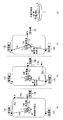
次に、図2乃至図4を参照して、被写体の位置と向きの検出方法について説明する。
ステージ10周辺の3箇所に受信機13A,13B,13Cを設ける。受信機13A,13B,13C間のそれぞれの距離は既知とする。
Next, a method for detecting the position and orientation of the subject will be described with reference to FIGS.
また、受信機13A,13B,13Cの位置はGPS(全地球測位システム、Global Posioning Systemの略)等で絶対値(緯度、経度)が既知となっている。被写体11は周波数の違う無指向性の発信機12R,12Lを所持している。
Further, the absolute values (latitude and longitude) of the positions of the
ステージ10上の位置Xに右肩が位置した時、図2(a)に示すように発信機12Rからの電波の届く時間差から受信機13A,13Bと位置Xまでの距離(Ra,Rb)が分かるので、発信機12Rの位置の候補としてXとX’の位置が分かる。
When the right shoulder is positioned at the position X on the
次に図2(b)に示すように発信機Rからの電波の届く時間差から受信機13B,13Cと位置Xまでの距離(Rb,Rc)が分かり、発信機12Rの位置の候補としてXとX″の位置が分かる。図2(a)と図2(b)を比較して、共通の候補がXであるので、発信機12Rの位置としてXが確定する。
Next, as shown in FIG. 2 (b), the distance (Rb, Rc) between the
同様にして、左肩の位置Yを、図2(c)に示すように発信機12Lと受信機13A,13B、13Cを用いて求めることができる。即ち、受信機13A,13Bと位置Yまでの距離(La,Lb)が分かるので、発信機12Lの位置の候補としてYとY’の位置が分かる。また、受信機13B,13Cと位置Yまでの距離(Lb,Lc)が分かり、発信機12Lの位置の候補としてYとY″の位置が分かる。ただしY’とY″は図示していない。そして、共通の候補がYであるので、発信機12Lの位置としてYが確定する。
Similarly, the position Y of the left shoulder can be obtained using the
このように、右肩Rと左肩Lの位置X,Yが確定すると、図2(c)に示すように右肩Rと左肩Lを結んだ線の中心を原点として、左肩Lの位置Yから時計回りに90度回転した方向が被写体11の正面の向きになる。 Thus, when the positions X and Y of the right shoulder R and the left shoulder L are determined, the center of the line connecting the right shoulder R and the left shoulder L as shown in FIG. The direction rotated 90 degrees clockwise is the front direction of the subject 11.
なお、顔を被写体の向きとするなら、両耳部付近に発信機12R,12Lを装着すればよい。
If the face is the direction of the subject,
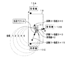
図3及び図4は指向性のある発信機を用いて被写体の向きを検出する例を示している。被写体の向きは、発信機と受信機間の距離と電波の強度のベクトルにより求められる。 3 and 4 show an example in which the direction of a subject is detected using a transmitter having directivity. The direction of the subject is obtained from a vector of the distance between the transmitter and the receiver and the intensity of the radio wave.
図3は、被写体11を中心に被写体の向き(例えば、正面)に強い電界分布を伴う指向性を持つ電波を発信するタイプの発信機H1の場合で、例えば被写体11の頭頂部Xに前記のタイプの発信機H1を装着している。 FIG. 3 shows a case of a transmitter H1 of a type that emits radio waves having directivity with a strong electric field distribution in the direction of the subject (for example, the front) around the subject 11, for example, the above-mentioned head X on the subject 11 A type transmitter H1 is installed.
被写体の向きにより電波の強度は図3のように、広がりがあり、受信機13Aは強度Ka、受信機13Bは強度Kb、受信機13Cは強度Kcとなるので、X点からベクトル合成した値(太い矢印にて示す)が被写体11の正面方向となる。
As shown in FIG. 3, the intensity of the radio wave varies depending on the direction of the subject. The
図4は、被写体11の一方方向に強い電界分布を伴う指向性を持つ電波を発信するタイプの発信機H2の場合で、例えば被写体11の胸に発信機H2を取り付け、被写体11の正面方向に電波を発信する。電波は被写体11の背面方向には強度0の分布を有している。被写体11の方向は、図3と同様に電界強度と距離のベクトル和(太い矢印にて示す)から算出する。但し、電波の指向性は、被写体がどこを向いていても1台以上の受信機に電波が届くように設定する。
FIG. 4 shows a transmitter H2 of a type that transmits a radio wave having directivity with a strong electric field distribution in one direction of the subject 11. For example, the transmitter H2 is attached to the chest of the subject 11 and the subject 11 is directed in the front direction. Send radio waves. The radio wave has a distribution of
また、発信機H2の取付け位置は、胸に限ることなく、例えば背中に取付け信号が弱い方向が正面と判断しても良いし、受信機13A,13B,13Cの位置もステージ10上の被写体11の位置・方向が分かるのであればどこに設置しても構わない。
Further, the mounting position of the transmitter H2 is not limited to the chest. For example, the direction in which the mounting signal is weak on the back may be determined to be the front, and the positions of the
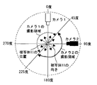
図5は、方向検出により、複数カメラのどちらが選択され、撮影されるかの一例を示した図である。 FIG. 5 is a diagram showing an example of which one of a plurality of cameras is selected and photographed by direction detection.
図5では、被写体11に対してカメラ1が0度、カメラ2が90度に設置した時、カメラ1はの正面が、225度〜0度〜45度を向いたとき撮影し、カメラ2は被写体11の正面が、45度〜180度〜225度を向いた時に撮影する。被写体11が境界の45度、225度を向いた場合は、例えばカメラ1で撮影するように決めておいても良いし、直前まで選択されていたカメラで撮影する、等としても良い。
In FIG. 5, when the
尚、位置・方向を測定するのは、電波送受信機に限らず、赤外線送受信機、無線LANとPDA(個人用の携帯情報端末:Personal Digital Assistanceの略)を使った位置検出システム、レーザやGPS等の送受信機や、位置測定用には音声マイク、あるいはステージの床に感圧センサー等の位置検出手段を予め配置し、被写体が立っている位置から演算してもよい。 Note that the position and direction are not limited to the radio wave transmitter / receiver, but are also an infrared transmitter / receiver, a position detection system using a wireless LAN and a PDA (personal digital information terminal: Personal Digital Assistance), laser, GPS For example, a position detection means such as a pressure sensor may be arranged in advance on the floor of the stage, and calculation may be performed from the position where the subject stands.
また、方向と位置を検出する送受信機は複数の種類を使用しても良い。例えば、位置検出には電波送受信機、方向検出には赤外線送受信機等を用いるなどである。 Further, a plurality of types of transceivers for detecting the direction and position may be used. For example, a radio wave transmitter / receiver is used for position detection, and an infrared transmitter / receiver is used for direction detection.
また、被写体11は単数でなくても、発信周波数の違う発信機を複数の被写体に携帯させ、撮影者の指示で被写体を切替えて撮影しても良い。 Further, the subject 11 is not limited to a single subject, and a plurality of subjects may carry transmitters having different transmission frequencies, and the subject may be switched according to instructions from the photographer.
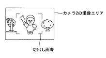
図6は、本発明の実施例2に係る撮像装置のブロック図である。図7は、カメラ2の画像から切出す部分を示している。 FIG. 6 is a block diagram of an image pickup apparatus according to Embodiment 2 of the present invention. FIG. 7 shows a portion cut out from the image of the camera 2.
図6で、図1の実施例1と異なる点は、実施例1に更に、画像切出し部17と解像度変換部18を設けた点と、方向・位置演算部14Aは受信機13A,13B,13Cで受信された被写体11の位置と向きの情報から被写体11の位置及び向きを算出する一方、算出された被写体のフィールド上の位置を、カメラ位置から見た被写体の座標位置(カメラ空間座標及び撮像素子平面座標)へ座標変換する機能を有している点である。方向・位置演算部14Aが、カメラ位置から見た被写体の座標位置へ座標変換する機能を有することにより、例えばカメラ2で撮影された被写体部分がカメラ2の撮像エリアのどの部分(座標)であるかを画像切出し部17に与え、画像切出し部17にて撮像画像の中の被写体部分を正確に切り出すことができる。
6 differs from the first embodiment of FIG. 1 in that an
図6の実施例2では、カメラ1,2のうち例えばカメラ2の出力画像の中の正面向きの被写体部分を、図7に示すようにカメラ2の撮像エリアの中から切り出して、切り出された画像を解像度変換部18にて解像度変換して表示装置に合った画素数にしてモニタ16に出力する。なお、モニタ16の代わりにDVDレコーダ等のレコーダを接続して撮影した画像を記録することも可能である。
In the second embodiment of FIG. 6, for example, a front-facing subject portion in the output image of the camera 2 is cut out from the imaging area of the camera 2 as shown in FIG. 7. The resolution of the image is converted by the
画像を切り出す領域を決めるには、受信機13A,13B,13Cによって被写体11のフィールド空間の座標位置を特定し、そのフィールド座標位置をカメラ位置から見た被写体の座標位置(カメラ空間座標及び撮像素子平面座標)へ座標変換を行って、被写体部分の画像を切り出す。
In order to determine a region to cut out the image, the coordinate position of the subject 11 in the field space is specified by the
ここで、本件出願人が2003年12月1日に特許出願した特願2003-402275号における画像切出しにつき、説明する。この既出願では、フィールド座標を、撮像手段が存在する位置に関わらない情報により表現されるカメラ空間の座標、撮像素子平面座標に座標変換する。被写体のフィールド座標位置が算出(検出)できれば、撮像手段による撮像領域上での被写体位置を求めて、その部分を切り出すことができる、ことが記載されている。以下に、特願2003-402275号における図1,図6,図12を、図8,図9,図10として説明する。 Here, the image extraction in Japanese Patent Application No. 2003-402275 filed on December 1, 2003 by the present applicant will be described. In this existing application, the field coordinates are coordinate-converted to the coordinates of the camera space and the image sensor plane coordinates expressed by the information regardless of the position where the imaging means is present. It is described that if the field coordinate position of the subject can be calculated (detected), the subject position on the imaging region by the imaging means can be obtained and the portion can be cut out. Hereinafter, FIGS. 1, 6, and 12 in Japanese Patent Application No. 2003-402275 will be described as FIGS. 8, 9, and 10. FIG.
まず、図8〜図10に関連する用語の説明をする。
注目点:注目対象に含む、或いは、注目対象の近傍にある点で、被写体に付けたセンサ等の検出対象を指す。
First, terms related to FIGS. 8 to 10 will be described.
Point of interest: A point that is included in or near the target of interest and indicates a detection target such as a sensor attached to the subject.
フィールド:注目対象を含んだ測定可能な空間(領域)で、この空間の所定の基準位置に対する注目点の相対的な位置を位置情報として算出可能な1つの座標系を指す。地球上の経度,緯度で表される座標系もフィールドである。或いは、注目対象がサッカー選手の場合、サッカー場をフィールドとして扱うこともでき、また、注目対象がステージ上の出演者である場合、ステージをフィールドとして扱うこともできる。 Field: A measurable space (region) that includes a target of interest, and refers to one coordinate system in which the relative position of the target point with respect to a predetermined reference position in this space can be calculated as position information. The coordinate system expressed by longitude and latitude on the earth is also a field. Alternatively, when the target of attention is a soccer player, the soccer field can be treated as a field, and when the target of attention is a performer on the stage, the stage can be treated as a field.
撮像領域:カメラ毎の撮像領域を示す。また、カメラの視野範囲にあり、更に、カメラの光学系におけるピント調整度合いが、所定レベル以上の領域を示す。原則、フィールド内を撮像する。 Imaging area: Indicates an imaging area for each camera. Further, it is within the field of view of the camera, and further indicates a region where the degree of focus adjustment in the camera optical system is equal to or higher than a predetermined level. In principle, the field is imaged.
カメラ空間:カメラの全撮像領域の画角を規定する線の交点を原点として撮像方向を軸(k)の1つとした座標系を指す。図9のi,j,kの空間である。ここで、画角を規定する線とは、図9に示したような、CCDなどの撮像素子の端の画素に結像する撮像領域を立体的に形づける線を示す。図9では、撮像素子平面の横方向に平行な軸iと撮像素子平面の縦方向に平行な軸jと撮像方向を示す軸kとの3つの軸で表現される座標系を指す。 Camera space: Refers to a coordinate system in which the intersection of lines defining the angle of view of the entire imaging area of the camera is the origin and the imaging direction is one of the axes (k). This is the space of i, j, k in FIG. Here, the line that defines the angle of view indicates a line that three-dimensionally forms an imaging region that forms an image on a pixel at the end of an imaging element such as a CCD, as shown in FIG. In FIG. 9, the coordinate system is expressed by three axes: an axis i parallel to the horizontal direction of the imaging element plane, an axis j parallel to the vertical direction of the imaging element plane, and an axis k indicating the imaging direction.
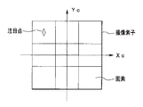
撮像素子平面座標:CCDなどの撮像素子が出力する画像データの横方向に関わる軸Xcと縦方向に関わる軸Ycの2つの軸で撮像素子の中心を原点とする座標系(図10参照)を指す。ただし、原点の位置は、撮像素子の中心に限定しない。左上の画素位置であっても良い。 Image sensor plane coordinates: A coordinate system (see FIG. 10) having the center of the image sensor as the origin on two axes, the axis Xc related to the horizontal direction of the image data output from the image sensor such as a CCD and the axis Yc related to the vertical direction. Point to. However, the position of the origin is not limited to the center of the image sensor. It may be the pixel position at the upper left.
図8に示す撮像装置は、フィールド空間を撮像し、動画像信号及び撮像領域情報を出力する撮像手段31と、注目対象における注目点の位置を検出する注目点検出手段32と、撮像手段31からの撮像領域情報と注目点検出手段32からの注目点位置の検出結果に基づいて注目対象の切出し位置を決定する切出し位置決定手段33と、撮像手段31からの動画像信号を入力し、切出し位置決定手段33からの切出し位置情報に基づいて動画像信号から所定の画像サイズを切り出す所定の画像サイズの画像切出し手段34と、切り出された所定の画像サイズの切出し動画像信号を所定の信号レベルにして出力する切出し画像出力手段35と、を備えて構成されている。
The imaging apparatus shown in FIG. 8 includes an
撮像手段31は、例えば、被写体像を撮像面に集光する撮影レンズ部と、撮像面上の全領域に集光された光電変換し、画素毎の動画像信号として出力する撮像素子であるイメージセンサと、イメージセンサにて撮像された動画像信号をデジタル信号に変換して出力するA/D変換回路と、イメージセンサを同期信号を含むタイミングパルスにて駆動する駆動回路1と、を備えて構成されている。
The imaging means 31 is, for example, an imaging lens unit that condenses a subject image on an imaging surface, and an imaging element that performs photoelectric conversion on all areas on the imaging surface and outputs as a moving image signal for each pixel. A sensor; an A / D conversion circuit that converts a moving image signal captured by the image sensor into a digital signal and outputs the digital signal; and a
注目点検出手段32には、GPSのように注目対象物に装着するセンサによって、そのセンサの位置情報を検出する手段、或いは、注目対象物にセンサなどを装着しないで位置検出する手段である。注目点検出手段32の検出結果とは、フィールド座標における注目点の位置情報(時にサイズ情報を含んでも良い)である。ただし、注目点検出手段32は、撮像手段31そのものの映像信号を画像処理して注目対象物を検出するものを含まない。即ち、撮像手段31を含まない検出手段である。 The attention point detection means 32 is a means for detecting position information of a sensor by a sensor attached to the attention object, such as GPS, or a means for detecting a position without attaching a sensor or the like to the attention object. The detection result of the attention point detection means 32 is position information of the attention point in the field coordinates (sometimes size information may be included). However, the point-of-interest detection means 32 does not include one that detects the target object by performing image processing on the video signal of the imaging means 31 itself. That is, the detection means does not include the imaging means 31.
また、注目点検出手段32が上記センサで注目点を検出するには、該注目点検出手段32にそのセンサ以外に基地局として表現する受信機、或いは、送信機を構成する必要がある。基地局が送信機である場合には、センサが受信機として、基地局の位置に対応したセンサ位置を検出する。また、基地局が受信機である場合には、センサが送信機として、基地局の位置に対応したセンサ位置を検出する。 In addition, in order for the point of interest detection means 32 to detect the point of interest with the above-described sensor, it is necessary to configure a receiver or transmitter that is expressed as a base station in addition to the sensor of interest point detection means 32. When the base station is a transmitter, the sensor serves as a receiver to detect a sensor position corresponding to the position of the base station. When the base station is a receiver, the sensor serves as a transmitter to detect a sensor position corresponding to the position of the base station.
切出し位置決定手段33は、画像切出し手段34が撮像手段31からの全撮像領域の全撮像画像に対して一部を切出して出力する際の、該一部である切出し画像の位置を指定する手段であり、関係情報生成手段である関係情報生成部331と、注目対象サイズ情報記憶部332と、画像切出位置算出部333とを備えている。
The cut-out position determining unit 33 is a unit that designates the position of a cut-out image that is a part when the image cut-out
関係情報生成部331は、フィールドの3次元空間の各位置と、カメラ空間との関係情報を生成する生成手段、或いは、フィールドの3次元空間の各位置と、2次元空間の撮像素子平面座標との関係情報を生成する生成手段である。
The relationship
関係情報は、フィールド座標をカメラ座標又は撮像素子平面座標に変換する際の対応関係をテーブルとしたテーブル情報、或いは、その関係を示す座標変換式、或いは、その式を表すパラメータなどである。 The relationship information is table information using a correspondence relationship when converting field coordinates to camera coordinates or imaging element plane coordinates as a table, a coordinate conversion expression indicating the relationship, or a parameter representing the expression.
注目対象サイズ情報記憶部332は、フィールドにおける実際の対象物のサイズ情報であってもよいし、撮像画像における対象物のサイズ情報であってもよい。 The target size information storage unit 332 may be actual size information of the target object in the field, or may be size information of the target object in the captured image.
画像切出位置算出部333は、注目点検出手段32からの検出結果と、関係情報生成部331からの関係情報と、注目対象サイズ情報記憶部332からの注目対象のサイズ情報とに応じて、画像を切り出す位置を決定する手段である。
The image cut-out position calculation unit 333 is configured according to the detection result from the attention
なお、図8における関係情報生成部331及び画像切出し位置算出部333を含む切出し位置決定手段33は、図6の実施例では方向・位置演算部14A内に構成されており、方向・位置演算部14A内の前記切出し位置決定手段から読み出しアドレス(撮影データのどこを読み出すかを示す情報)が出力され、画像切出し部17に切出し情報として与えられる。画像切出し部17は、カメラ1,2のうちの選択された方のカメラの撮影データを記憶するためのメモリで構成されていて、切出し位置情報として前記読み出しアドレスが与えられて、画像の切出しが行なわれることになる。
Note that the cutout position determination means 33 including the relationship
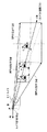
図9は、サッカー場をフィールド空間とした場合の、そのフィールド空間とカメラの撮像領域との相互関係を示している。カメラの撮像領域は画角を規定する4本の線によって囲まれた空間領域を指している。画角を規定する4本の線の交点がカメラ空間の原点Oである。カメラの撮像領域内には選手A,B,Cが存在している。i,j,k軸は撮像手段31であるカメラが撮像する方向及び/又はカメラが撮像する画角を基準とするカメラ座標を示している。カメラの撮影領域における注目点の位置は、注目点検出手段32で検出するフィールドにおける注目点の座標と、前述した関係情報とによって算出することができる。
FIG. 9 shows the correlation between the field space and the imaging area of the camera when the soccer field is a field space. The imaging area of the camera indicates a spatial area surrounded by four lines that define the angle of view. The intersection of the four lines that define the angle of view is the origin O of the camera space. Players A, B, and C exist in the imaging area of the camera. The i, j, and k axes indicate camera coordinates based on the direction and / or the angle of view captured by the camera that is the
図10に、撮像素子平面の座標系を示す。図9のカメラ座標系における注目点(k軸に直交する平面上に存在している)においては、図10に示すような(Xc,Yc)で表される撮像素子平面座標平面上の位置に変換することができる。なお、図10において撮像素子は、縦3画素、横3画素として示してあるが、勿論、それに限定されるものではない。 FIG. 10 shows a coordinate system of the imaging element plane. At the point of interest in the camera coordinate system of FIG. 9 (which exists on a plane orthogonal to the k-axis), it is at a position on the imaging element plane coordinate plane represented by (Xc, Yc) as shown in FIG. Can be converted. In FIG. 10, the image sensor is shown as three vertical pixels and three horizontal pixels, but of course, the present invention is not limited to this.
図6の方向・位置演算部14Aにおいて、画像を切出す領域を決めるには、受信機13A,13B,13Cによって被写体11のフィールド座標位置(又はステージ上の座標位置)を特定し、次にカメラ位置から見た座標位置へ座標変換を行い、更にカメラ1又は2内の撮像素子から見た座標系に変換し、被写体11に対応する部分の領域を画像の切出し領域として決定する。カメラ1又は2の選択は、方向・位置演算部14Aからの被写体の方向の情報によって行われ、カメラ選択部15で被写体が正面向きに撮影された方のカメラが選択される。そして、その選択されたカメラの撮像データが画像切出し部17に取り込まれると、方向・位置演算部14Aにおいて決定された切出し領域の情報に基づいて画像の切出しが行われる。
In order to determine a region to cut out an image in the direction /
次に、記録・再生方法について図1、図6、及び図11〜15を用いて説明する。
目標被写体が一つの場合は、例えば図1(カメラ切替えのみ)あるいは、図6(画像切出し有り)のモニタ入力部にHDDサーバー、DVDレコーダ等のレコーダを接続すれば良い。図11〜図15は目標被写体が複数で、各被写体毎に個別に切出しデータを作成する方法を示している。
Next, a recording / reproducing method will be described with reference to FIGS. 1, 6, and 11 to 15. FIG.
When there is one target subject, for example, a recorder such as an HDD server or a DVD recorder may be connected to the monitor input unit shown in FIG. 1 (only camera switching) or FIG. 6 (with image cutout). FIGS. 11 to 15 show a method of creating cut data individually for each subject when there are a plurality of target subjects.
図11は、本発明の実施例3に係る撮像装置のブロック図であって、複数の被写体の記録を各被写体のIDとともに残す記録システムを示している。
FIG. 11 is a block diagram of an image pickup apparatus according to
図11において、図6と異なる点は、カメラ1,2で、複数(図では2人)の被写体11,11’を撮影する点と、複数(図では2人)の被写体11,11’はそれぞれの右肩,左肩を識別可能な情報だけでなく、各被写体を識別可能な識別番号(ID)を送信可能に構成された発信機(12R,12L)、(12’R,12’L)を所持している点と、方向・位置演算部14Bは、受信機13A,13B,13Cで受信された被写体11,11’の位置と向きの情報から被写体11,11’の位置及び向きを算出する一方、算出された被写体11,11’のフィールド上の位置を、カメラ位置から見た被写体の座標位置(カメラ空間座標及び撮像素子平面座標)へ座標変換する機能を有する点と、カメラ選択部に相当するものがなく、カメラ1,2からの撮像データは一方のみが選択されることはなく、カメラ1,2からのカメラ毎の全ての撮像データを、撮影した被写体11,11’の位置及び向きに対応付けて記録するレコーダとしてのサーバー19を有している点とである。なお、サーバー19はHDDサーバーであっても、DVDレコーダであってもよいが、HDDサーバーの方が大記憶容量のものが構成可能であるので、複数の被写体データを記録するのに有利である。
11 differs from FIG. 6 in that the
図11では、記録時には、全てのカメラ1,2の全画像と、被写体位置及び向きの情報をリンクして記録する。
In FIG. 11, at the time of recording, all the images of all the
再生時は、画像データから被写体位置及び向きの情報に基づいて被写体情報を切出して出力すればよい。 At the time of reproduction, the subject information may be extracted from the image data based on the subject position and orientation information and output.
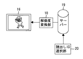
図12は図11の記録システムで記録した映像データを被写体のIDを指定して再生する再生システムを示している。 FIG. 12 shows a playback system for playing back video data recorded by the recording system of FIG.
図12においては、サーバー19には、複数の被写体11,11’について、それらのIDとともに記録される撮像データ、各IDごとの被写体の位置及び向きを示すデータ、記録されている各IDの撮像データから被写体の向きに応じた切出し位置を示す座標データなど、が記録されている。
In FIG. 12, the
操作部に設けられた読出しID選択部20を操作することによって、サーバー19に被写体IDとともに記録された撮像データから読み出したい被写体の撮像データを指定することができる。
By operating a read
解像度変換部18は、サーバー19内のメモリからそのIDの被写体の撮像データを切出して読み出し、表示装置に合った解像度に変換してモニタ16に出力するものである。
The
図13は、図12の再生時のフローチャートを示している。
図13に示すように、ユーザーがある被写体のIDを指定すると(ステップS1)、サーバー19内の画像データが記録されているメモリから、その指定されたIDの被写体が正面向きに写っている被写体の位置・方向データのアドレスに従って(ステップS2)、そのIDの被写体の画像データを切出して読み出し(ステップS3)、解像度変換部18にて表示装置に合った解像度に変換した後(ステップS4)、モニタ16に表示する(ステップS5)。
FIG. 13 shows a flowchart at the time of reproduction in FIG.
As shown in FIG. 13, when the user designates the ID of a subject (step S1), the subject in which the subject with the designated ID is reflected in the front direction from the memory in which the image data in the
以上に補足して説明すると、記録時には、サーバー19には、カメラ1とカメラ2で撮影した全ての撮像データと、方向・位置演算部14Bで演算した方向及び位置のデータとが少なくとも記録されるので、再生時にはID01を指定すると、ID01の再生データとしてカメラ1,2のデータの中からID01の正面を向いている方のカメラのデータを選択して再生する。
In addition to the above description, at the time of recording, the
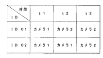
今、図14のように時間t1では、ID01がカメラ1の向きになっていて、時間t2,t3ではID01がカメラ2の向きになっており、一方、時間t1,t2ではID02がカメラ1の向きになっていて、時間t3では、ID02もカメラ2の向きになっている、とする。
As shown in FIG. 14, ID01 is in the direction of
時間経過に従う、2つの被写体ID01,ID02の向きが、図14のようになっているとすると、再生時に、ID01を指定すると、時間t1では、ID01の再生データとしてID01が正面向きに撮影されたカメラ1,2のデータの中から選択して再生し、時間t2,t3では、カメラ2のデータが選択されて再生される。同様に、ID02を指定すると、時間t1,t2では、カメラ1のデータが再生され、時間t3では、カメラ2のデータが再生される。
Assuming that the orientations of the two subjects ID01 and ID02 according to the passage of time are as shown in FIG. 14, when ID01 is designated at the time of reproduction, ID01 is photographed in the front direction as reproduction data of ID01 at time t1. The data of the
なお、このようにカメラ1とカメラ2の画素を選択して再生表示する場合、例えばID01を選択してカメラ1の画素を再生する場合、単にカメラ1で撮影したままの被写体ID01が正面向きの全体画像を再生表示してもよいし、ID01の正面向きの切出し画像(例えばアップ画像)を再生表示してもよい。ID02を選択した場合も同様に、カメラ1或いは2でID02を正面向きで撮影した全体画像を再生表示してもよいし、ID02の正面向きの切出し画像(例えばアップ画像)を再生表示してもよい。
Note that when the pixels of the
図示していないが、例えば4人の被写体がある場合、4個のIDを指定し、モニタを4分割して、同時に4つの切出し画像を1枚にして1台のモニタに表示するように構成してもよい。 Although not shown, for example, when there are four subjects, four IDs are specified, the monitor is divided into four, and four cut-out images are displayed as a single image on one monitor at the same time. May be.
図15は、図12におけるモニタに代えてDVD等のレコーダ21を接続したものであり、読出しID選択部20の指示に従って、サーバー19から読み出された指定IDの切出しデータを、表示装置の解像度に合うように解像度変換部18にて解像度変換した後、例えばDVDレコーダ21にて2次記録媒体であるDVD−Rなどに記録することができる。このようにすれば、例えばHDDサーバーからID01を指定して記録を行うと、ID01用データのみが記録されたDVDを得ることができ、ID02を指定して記録を行うと、ID02用データのみが記録されたDVDを得ることができ、個別IDデータ毎に2次記録媒体に記録して、配布あるいは販売等に供することができる。
FIG. 15 is a diagram in which a
図16は、本発明の実施例4に係る撮像装置のブロック図である。図17は、図16における撮像手段(カメラ1A又はカメラ2A)のみの構成を示すもので、画像切出しを撮像素子内で行い、カメラ1A又は2Aから出力された時には既に切り出された画像が出力されるようなっている。
FIG. 16 is a block diagram of an image pickup apparatus according to
図16において、ステージ10、被写体11、発信機12R,12L、受信機13A,13B,13C、カメラ選択部15、及び、モニタ16は、図1と同様である。なお、モニタ16の代わりにDVDレコーダ等のレコーダを接続して撮影した画像を記録することも可能である。
16, the
カメラ1A,2A、及び、方向・位置演算部14Cが図1とは異なっている。カメラ1A(又は2A)は、図17に示すような構成となっている。
The
方向・位置演算部14Cは、受信機13A,13B,13Cで受信された被写体11の位置と向きの情報から被写体11の位置及び向きを算出する一方、算出された被写体11のフィールド上の位置を、カメラ位置から見た被写体の座標位置(カメラ空間座標及び撮像素子平面座標)へ座標変換する機能を有し、且つ切出し位置を選択すべく切出し位置指示を行う機能を有している。方向・位置演算部14Cは、算出された被写体11の向き(カメラ1Aの向きかカメラ2Aの向きか)によってカメラ選択部15を切り替えるための選択信号を出力する機能も有している。
The direction / position calculation unit 14C calculates the position and orientation of the subject 11 from the position and orientation information of the subject 11 received by the
カメラ1A(又は2A)は、図17に示すように、撮像素子41と、方向・位置演算部14Cからの切出し位置指示を受けて前記撮像素子41に対して画像切出しなどの制御を行うシステム制御マイコン42と、撮像素子41から読み出された電荷を電圧に変換する電荷電圧変換部43と、CDS処理,ゲイン調整及びデジタル信号変換などを行うカメラ信号処理部44と、表示装置の解像度に合うように解像度変換を行う解像度変換部45と、アナログ信号変換を行うD/A変換器46と、を有して構成されている。
As shown in FIG. 17, the
さらに、撮像素子41は、受光素子としてのフォトダイオードを多数(例えば800万画素)備え、光電変換を行う光電変換部411と、システム制御マイコン42からの切出し位置指示に基づき、光電変換部に生成される画像の切出し領域を指定する切出し領域指定部412と、切出し領域指定部412によって垂直方向の画像数読出し範囲を指定する水平読出し位置指定部413と、切出し領域指定部412によって水平走査線上の画像数読出し範囲を指定する走査線読出し部414と、を有している。
Further, the
なお、撮像素子41としては、C−MOSセンサーでも、CCDであってもよいが、何れの場合も、光電変換部(画素領域)の任意の部分が読み出せる機能を持ったセンサーであることが必要である。
The
以上の構成においては、方向・位置演算部14Cで撮像素子41の切出し領域を決定し、その領域指定データをカメラ1A(又は2A)のマイコン42に送る。マイコン42から撮像素子41内のどの部分を切出すかアドレス指定することにより、必要な部分のみ切出すことができる。その後、解像度変換部45にて所定の解像度変換を行い、通常のテレビジョンモニタ16に表示可能な状態で出力する。
In the above configuration, the cutout area of the
水平読出し位置指定部413と走査線読出し部414による切出し領域の指定は、まず、水平読出し位置指定部413で水平読出し位置指定して、上下の不要な走査線は読み飛ばし、走査線読出し部414のところで、水平方向の左右部分は読み捨ててしまうことで切出し領域指定を行うことができる。
In order to designate the cut-out area by the horizontal readout
画像を切出す領域を決めるには、方向・位置演算部14Cにおいて、受信機13A,13B,13Cによって被写体11のフィールド座標位置(又はステージ上の座標位置)を特定し、次にカメラ位置から見た座標位置へ座標変換を行い、更に撮像素子から見た座標系に変換し、被写体11に対応する部分の領域を画像の切出し領域として決定する。
In order to determine the area to be cut out, the direction / position calculation unit 14C specifies the field coordinate position (or the coordinate position on the stage) of the subject 11 by the
画像処理を用いることなく、発信機と受信機を用いて、被写体の位置だけでなく、被写体の向きを検出することができるので、被写体が正面或いは顔を向けた状態を自動的に検出して、撮影でき、カメラの利便性をより高めることが可能となる。注目対象に追従して画像を切出しする撮像システムにおける画像処理装置に広く利用することが可能となる。 Without using image processing, it is possible to detect not only the position of the subject but also the orientation of the subject using the transmitter and the receiver, so that the state where the subject is facing the front or face is automatically detected. Therefore, it is possible to shoot and to improve the convenience of the camera. It can be widely used in image processing apparatuses in an imaging system that cuts out an image following a target of interest.
1,2,1A,2A…撮影手段(カメラ)
11…被写体
12R,12L…発信機(位置方向情報発信手段)
13A,13B,13C…受信機(受信手段)
14,14A,14B,14C…方向・位置演算部(被写体位置方向算出手段)
15…カメラ選択部
16…モニタ(表示手段)
代理人 弁理士 伊 藤 進
1, 2, 1A, 2A ... photographing means (camera)
11: Subject 12R, 12L: Transmitter (Position / Direction Information Transmitting Unit)
13A, 13B, 13C ... Receiver (receiving means)
14, 14A, 14B, 14C ... direction / position calculation unit (subject position / direction calculation means)
15 ...
Agent Patent Attorney Susumu Ito
Claims (16)
前記撮像手段により撮影される被写体の位置情報および方向情報を発信する位置方向情報発信手段と、
前記位置方向情報発信手段からの位置情報と方向情報を受信する受信手段と、
前記受信手段により受信された被写体の位置情報と方向情報から、被写体の位置および方向を算出する被写体位置方向算出手段とを有し、
前記被写体位置方向算出手段により算出された被写体の位置及び方向から、被写体を撮影する撮像手段を前記複数の撮像手段から選択し、被写体の画像を撮影することを特徴とする撮像装置。 A plurality of imaging means provided at different positions and oriented in different directions;
Position and direction information transmitting means for transmitting position information and direction information of a subject imaged by the imaging means;
Receiving means for receiving position information and direction information from the position / direction information transmitting means;
Subject position / direction calculation means for calculating the position and direction of the subject from the position information and direction information of the subject received by the receiving means;
An image pickup apparatus for picking up an image of a subject by selecting an image pickup means for photographing a subject from the plurality of image pickup means based on the position and direction of the subject calculated by the subject position direction calculation means.
選択された撮像手段により撮像された画像を記録する記録部と、
をさらに有することを特徴とする請求項1に記載の撮像装置。 An imaging means selection unit connected to the plurality of imaging means and selecting an imaging means according to information from the subject position direction calculation means;
A recording unit for recording an image captured by the selected imaging unit;
The imaging apparatus according to claim 1, further comprising:
この画像切出し手段により切出された画像を表示する表示手段と、
前記画像切出し手段により切出された画像を表示手段の解像度に合わせて解像度変換する解像度変換手段と、
を有することを特徴とする請求項1に記載の撮像装置。 Image cutting means for cutting out a part of the image of the subject imaged by the imaging means selected from the plurality of imaging means so as to include the subject based on the calculation result of the subject position direction calculation means;
Display means for displaying the image cut out by the image cutting means;
Resolution conversion means for converting the resolution of the image cut out by the image cutting means in accordance with the resolution of the display means;
The imaging apparatus according to claim 1, further comprising:
前記画像切出し手段は前記記録部に記録された被写体認識信号をもとに、前記記録部に記録された画像から被写体を含むように切出した画像信号を出力することを特徴とする請求項13に記載の撮像装置。 The recording unit records a subject recognition signal transmitted from the position / direction information transmitting unit,
The image cutting means outputs an image signal cut out so as to include a subject from an image recorded in the recording unit based on a subject recognition signal recorded in the recording unit. The imaging device described.
前記複数の撮像手段から選択された撮像手段により撮影された被写体の画像の一部を、前記被写体位置方向算出手段の算出結果に基づき被写体を含むように切出す位置を指示する切出し位置指示手段と、
前記画切出し位置指示手段からの切出し位置指示に基づき、前記撮像素子内の切出す領域を指定する切出し領域指定手段とをさらに有しており、
この切出し領域指定手段により前記撮像素子により撮影された被写体像を切出すことを特徴とする請求項1に記載の撮像装置。 The imaging means has an imaging device having a plurality of pixels,
A cutout position instruction means for instructing a position to cut out a part of an image of a subject imaged by the image pickup means selected from the plurality of image pickup means so as to include a subject based on a calculation result of the subject position direction calculation means; ,
Based on a cutout position instruction from the image cutout position instruction means, further comprising a cutout area designation means for designating a cutout area in the image sensor,
The imaging apparatus according to claim 1, wherein a subject image photographed by the imaging device is cut out by the cut-out area specifying unit.
フィールド上に存在する前記被写体の位置情報および方向情報を発信する被写体位置方向発信手段と、
前記被写体位置方向発信手段からの位置情報と方向情報を受信する受信手段と、
前記受信手段により受信された被写体の位置情報と方向情報から、フィールド上の被写体の位置および方向を算出する被写体位置方向算出手段と、
前記被写体位置方向算出手段にて算出されたフィールド上の被写体の位置及び方向を、前記撮像手段が撮像する方向及び/又は画角を基準とするカメラ座標、或いは撮像手段が撮像する撮像素子平面座標に変換する座標変換手段とを有し、
この座標変換手段により変換された被写体の座標および向きから、被写体を撮影する撮像手段を前記複数の撮像手段から選択し、被写体の画像を撮影することを特徴とする撮像装置。 A plurality of imaging means provided at different positions and directions on the field and obtaining image information including a subject;
Subject position direction transmitting means for transmitting position information and direction information of the subject existing on the field;
Receiving means for receiving position information and direction information from the subject position direction transmitting means;
Subject position / direction calculation means for calculating the position and direction of the subject on the field from the subject position information and direction information received by the receiving means;
The position and direction of the subject on the field calculated by the subject position / direction calculating means are the camera coordinates based on the direction and / or the angle of view taken by the imaging means, or the imaging element plane coordinates taken by the imaging means. Coordinate conversion means for converting to
An image pickup apparatus for picking up an image of a subject by selecting an image pickup means for photographing an object from the plurality of image pickup means based on the coordinates and orientation of the subject converted by the coordinate conversion means.
Priority Applications (1)
| Application Number | Priority Date | Filing Date | Title |
|---|---|---|---|
| JP2004093542A JP2005286419A (en) | 2004-03-26 | 2004-03-26 | Image pickup device |
Applications Claiming Priority (1)
| Application Number | Priority Date | Filing Date | Title |
|---|---|---|---|
| JP2004093542A JP2005286419A (en) | 2004-03-26 | 2004-03-26 | Image pickup device |
Publications (2)
| Publication Number | Publication Date |
|---|---|
| JP2005286419A true JP2005286419A (en) | 2005-10-13 |
| JP2005286419A5 JP2005286419A5 (en) | 2007-04-26 |
Family
ID=35184378
Family Applications (1)
| Application Number | Title | Priority Date | Filing Date |
|---|---|---|---|
| JP2004093542A Pending JP2005286419A (en) | 2004-03-26 | 2004-03-26 | Image pickup device |
Country Status (1)
| Country | Link |
|---|---|
| JP (1) | JP2005286419A (en) |
Cited By (2)
| Publication number | Priority date | Publication date | Assignee | Title |
|---|---|---|---|---|
| US9942471B2 (en) | 2012-10-05 | 2018-04-10 | Fuji Xerox Co., Ltd. | Information processing apparatus, information processing system and non-transitory computer readable medium |
| KR102472144B1 (en) * | 2022-02-21 | 2022-12-01 | 주식회사 서큘러스 | Interaction robot, and control method for the same |
-
2004
- 2004-03-26 JP JP2004093542A patent/JP2005286419A/en active Pending
Cited By (2)
| Publication number | Priority date | Publication date | Assignee | Title |
|---|---|---|---|---|
| US9942471B2 (en) | 2012-10-05 | 2018-04-10 | Fuji Xerox Co., Ltd. | Information processing apparatus, information processing system and non-transitory computer readable medium |
| KR102472144B1 (en) * | 2022-02-21 | 2022-12-01 | 주식회사 서큘러스 | Interaction robot, and control method for the same |
Similar Documents
| Publication | Publication Date | Title |
|---|---|---|
| US20050117033A1 (en) | Image processing device, calibration method thereof, and image processing | |
| EP2779620B1 (en) | Image generation device, and image generation method | |
| JP5428210B2 (en) | Information processing apparatus, imaging system, recording control method, and program | |
| US8836760B2 (en) | Image reproducing apparatus, image capturing apparatus, and control method therefor | |
| KR101694689B1 (en) | Method for generating video data and image photographing device thereof | |
| KR101321969B1 (en) | Image processing system and method therefor, image processing apparatus and method, image capturing appararus and method, program recording medium, and program | |
| US20070228159A1 (en) | Inquiry system, imaging device, inquiry device, information processing method, and program thereof | |
| CN102685365A (en) | Image synthesizing apparatus, image synthesizing method, and image synthesizing program | |
| JP2004531113A (en) | Omnidirectional three-dimensional image data acquisition apparatus by annotation, method and method for enlarging photosensitive area | |
| JP2009094724A (en) | Imaging apparatus | |
| US7643060B2 (en) | User guiding apparatus and an image capturing system, method and program for using same | |
| WO2017149124A1 (en) | A method, system and device for generating associated audio and visual signals in a wide angle image system | |
| KR20140011964A (en) | Visual surveillance and reconnaissance method using high-quality and omnidirectional video | |
| JP2008172342A (en) | Three-dimensional image recorder and three-dimensional image recording method | |
| JP2016127377A (en) | Image processing apparatus and image processing method, image reproducer and image reproducing method and program | |
| JP2008288745A (en) | Video information processing apparatus | |
| JP2010198104A (en) | Image display system, portable terminal system, portable terminal equipment, server, and image display method thereof | |
| JP2003264900A (en) | Acoustic providing system, acoustic acquisition apparatus, acoustic reproducing apparatus, method therefor, computer-readable recording medium, and acoustic providing program | |
| US20160127617A1 (en) | System for tracking the position of the shooting camera for shooting video films | |
| JP5098966B2 (en) | Imaging device | |
| JP2005286419A (en) | Image pickup device | |
| JP2009239346A (en) | Photographing device | |
| JP2010200084A (en) | Imaging apparatus | |
| CN117859339A (en) | Media device, control method and device thereof, and target tracking method and device | |
| JP2013141090A (en) | Imaging apparatus and processing method of the same |
Legal Events
| Date | Code | Title | Description |
|---|---|---|---|
| A521 | Request for written amendment filed |
Free format text: JAPANESE INTERMEDIATE CODE: A523 Effective date: 20070312 |
|
| A621 | Written request for application examination |
Free format text: JAPANESE INTERMEDIATE CODE: A621 Effective date: 20070312 |
|
| A977 | Report on retrieval |
Free format text: JAPANESE INTERMEDIATE CODE: A971007 Effective date: 20090916 |
|
| A131 | Notification of reasons for refusal |
Free format text: JAPANESE INTERMEDIATE CODE: A131 Effective date: 20091006 |
|
| A02 | Decision of refusal |
Free format text: JAPANESE INTERMEDIATE CODE: A02 Effective date: 20100302 |