JP2005284471A - Image processing apparatus and method - Google Patents
Image processing apparatus and method Download PDFInfo
- Publication number
- JP2005284471A JP2005284471A JP2004094516A JP2004094516A JP2005284471A JP 2005284471 A JP2005284471 A JP 2005284471A JP 2004094516 A JP2004094516 A JP 2004094516A JP 2004094516 A JP2004094516 A JP 2004094516A JP 2005284471 A JP2005284471 A JP 2005284471A
- Authority
- JP
- Japan
- Prior art keywords
- image
- information
- brightness value
- host vehicle
- road surface
- Prior art date
- Legal status (The legal status is an assumption and is not a legal conclusion. Google has not performed a legal analysis and makes no representation as to the accuracy of the status listed.)
- Pending
Links
- 238000012545 processing Methods 0.000 title claims abstract description 39
- 238000000034 method Methods 0.000 title claims description 15
- 238000001514 detection method Methods 0.000 claims description 31
- 238000003384 imaging method Methods 0.000 claims description 14
- 230000008569 process Effects 0.000 claims description 9
- 238000003672 processing method Methods 0.000 claims description 7
- 239000000284 extract Substances 0.000 claims description 2
- 238000010586 diagram Methods 0.000 description 16
- 238000012544 monitoring process Methods 0.000 description 7
- 230000004043 responsiveness Effects 0.000 description 6
- 238000012552 review Methods 0.000 description 4
- 238000000605 extraction Methods 0.000 description 3
- 238000006243 chemical reaction Methods 0.000 description 2
- 238000012546 transfer Methods 0.000 description 2
- 101100310622 Mus musculus Soga1 gene Proteins 0.000 description 1
- 230000008901 benefit Effects 0.000 description 1
- 230000008859 change Effects 0.000 description 1
- 230000000295 complement effect Effects 0.000 description 1
- 230000006835 compression Effects 0.000 description 1
- 238000007906 compression Methods 0.000 description 1
- 238000012217 deletion Methods 0.000 description 1
- 230000037430 deletion Effects 0.000 description 1
- 238000011161 development Methods 0.000 description 1
- 230000006872 improvement Effects 0.000 description 1
- 229910044991 metal oxide Inorganic materials 0.000 description 1
- 150000004706 metal oxides Chemical class 0.000 description 1
- 230000008520 organization Effects 0.000 description 1
- 230000004044 response Effects 0.000 description 1
- 239000004065 semiconductor Substances 0.000 description 1
- 230000026676 system process Effects 0.000 description 1
- 230000009466 transformation Effects 0.000 description 1
Images


Abstract
Description
本発明は、画像処理装置及び画像処理方法に関する。詳しくは、自動車等車両において、たとえば、先行車追尾などの車両走行支援システムに用いられる画像処理装置及び画像処理方法であって、とりわけ、撮影可能な限界明暗比が高い撮像デバイスの画像を処理する画像処理装置及び画像処理方法に関する。 The present invention relates to an image processing apparatus and an image processing method. Specifically, in a vehicle such as an automobile, for example, an image processing apparatus and an image processing method used in a vehicle travel support system such as tracking a preceding vehicle, and in particular, process an image of an imaging device having a high limitable contrast ratio. The present invention relates to an image processing apparatus and an image processing method.
ここで、“限界明暗比”とは、その撮像デバイスによって撮影可能な被写体の明るさ(明度又は輝度)の最低値と最大値の比のことをいう。通常は、デシベル値(ダイナミックレンジ)で表される。限界明暗比が高いほど、画像中の明るい部分や暗い部分を忠実に再現できる。 Here, the “limit light / dark ratio” refers to the ratio between the minimum value and the maximum value of the brightness (brightness or luminance) of a subject that can be photographed by the imaging device. Usually expressed in decibel values (dynamic range). The higher the limit light / dark ratio, the more accurately the bright and dark parts of the image can be reproduced.
一般に、先行車追尾システムなどにおいては、自車前方の車両(以下「先行車」という。)の位置や走行速度、自車との速度差及び先行車との距離(車間距離)などの様々な情報を必要とするが、かかる情報の取得に際しては、先行車の急な動き(急停止等)に即座に反応して所要の回避処置や制動処置等の緊急対策を速やかに講じなければならないため、とりわけ、高度な即応性(リアルタイム性)が求められる。 In general, in a preceding vehicle tracking system, various positions such as the position and travel speed of a vehicle in front of the own vehicle (hereinafter referred to as “preceding vehicle”), the speed difference from the own vehicle, and the distance from the preceding vehicle (inter-vehicle distance) are various. Information is required, but when obtaining such information, it is necessary to immediately respond to sudden movements of the preceding vehicle (sudden stop, etc.) and take emergency measures such as necessary avoidance measures and braking measures promptly. In particular, a high level of responsiveness (real time) is required.
この点について、特許文献1では、レーザレーダと撮像装置とを併用した技術が開示されている。この技術の要旨は、レーザレーダで検出した先行車情報を利用して、画像情報の特定領域(同文献では“処理エリア”)を切り出し、その切り出し領域のみを画像処理の対象とすることにより、無駄な画像処理を排除して、画像処理の高速化を達成するというものである。
In this regard,
この従来技術の撮像装置は、同文献中に明示されているようにCCD(電荷転送素子)カメラの使用を前提としているが、一般にCCDカメラのダイナミックレンジは、非特許文献1にも記載されているように高々30〜40dB程度に過ぎない。このダイナミックレンジは、太陽光に照らされた明るい被写体から夜間の暗い被写体までの多種多様な明るさの画像を撮影する場合の所要ダイナミックレンジ(100dB以上)を遙かに下回るため、特に、先行車追尾システムなどの車両搭載機器に適用する場合には、何らかのダイナミックレンジの向上策が不可欠である。
This prior art imaging device is premised on the use of a CCD (charge transfer device) camera as specified in the document, but the dynamic range of a CCD camera is generally described in
こうした対策としては、たとえば、非特許文献2に記載されているように、露光条件の異なる複数のシーンの画像を合成してダイナミックレンジを拡大する技術や、非特許文献3に記載されているように、ハードウェア処理によって画像の低空間周波数成分を抑制することによりダイナミックレンジを圧縮する技術などが知られている。しかし、いずれも、画像処理のオーバヘッドが大きく、リアルタイム性の点で好ましくないうえ、ハードウェア処理を必要とするものにあっては、コストの点でも好ましくない。
As such measures, for example, as described in Non-Patent
そこで、本件出願人は、先に、CCDカメラに代わる、高ダイナミックレンジな撮像デバイスであるCMOS(相補型金属酸化膜半導体)カメラを利用した「画像データ変換装置及びカメラ装置」(特願2004−42187/平成16年2月19日)を提案している。この提案技術は「ダイナミックレンジの広い画像データをダイナミックレンジの狭い画像データに良好に変換する」というものであり、上記の従来技術の不都合(オーバヘッドの問題やコストの問題)を招かないようにしたものである。 Therefore, the applicant of the present application previously described an “image data conversion apparatus and camera apparatus” (Japanese Patent Application No. 2004-2004) using a CMOS (complementary metal oxide semiconductor) camera, which is an imaging device with a high dynamic range, instead of a CCD camera. 42187 / February 19, 2004). This proposed technology is "Converting image data with a wide dynamic range into image data with a narrow dynamic range", so as not to incur the disadvantages (overhead problems and cost problems) of the above-mentioned conventional technology. Is.
CCDカメラと対比したときのCMOSカメラの利点の第一は、上記のとおりダイナミックレンジが広い(非特許文献1によれば130dBものCMOSカメラも実用化されている)ことであり、第二は、撮像素子のランダムアクセス(したがって、全画素のみならず、任意領域の画素情報の取り出し)が可能なことである。このCMOSカメラを利用すれば、上記の従来技術の不都合(オーバヘッドの問題やコストの問題)を招くことなく、屋外撮影における所要ダイナミックレンジ(100dB以上)を確保でき、しかも、ランダムアクセスによってCMOSカメラの特定領域の画像を取り出して、その特定領域の画像だけを画像処理の対象とすることにより、無駄な画像処理を排除し、画像処理の高速化(高度なリアルタイム性)も達成することができる。 The first advantage of a CMOS camera when compared with a CCD camera is that the dynamic range is wide as described above (a CMOS camera of 130 dB is also in practical use according to Non-Patent Document 1), and the second is It is possible to perform random access of the image sensor (thus, extraction of pixel information of an arbitrary region as well as all pixels). If this CMOS camera is used, the required dynamic range (over 100 dB) for outdoor photography can be ensured without incurring the disadvantages of the above-described prior art (overhead problems and cost problems). By taking out an image of a specific area and subjecting only the image of the specific area to image processing, useless image processing can be eliminated, and high-speed image processing (advanced real-time performance) can be achieved.
しかしながら、CMOSカメラの特定領域の画像、たとえば、先行車を含む特定領域の画像だけを画像処理の対象としただけでは、無駄な画像処理を完全に排除できない。上記のとおり、CMOSカメラのダイナミックレンジが相当広いため、当該特定領域の画像には“不要な明度情報”が多く含まれているからである。 However, wasteful image processing cannot be completely eliminated simply by using only an image of a specific area of a CMOS camera, for example, an image of a specific area including a preceding vehicle. As described above, since the dynamic range of the CMOS camera is quite wide, the image of the specific area includes a lot of “unnecessary brightness information”.
つまり、先行車を含む特定領域の画像には、その先行車の認識に必要な情報のみならず、太陽光などの高輝度情報や日陰などの低輝度情報も含まれており、且つ、CMOSカメラの高ダイナミックレンジによって、画像に占める、これらの不要な明度情報(太陽光などの高輝度情報や日陰などの低輝度情報)の割合が相当に大きいため、かかる不要な明度情報の分だけ無駄な画像処理を否めない。 That is, the image of the specific area including the preceding vehicle includes not only information necessary for the recognition of the preceding vehicle but also high luminance information such as sunlight and low luminance information such as shade, and the CMOS camera. Because of the high dynamic range, the ratio of these unnecessary brightness information (high brightness information such as sunlight and low brightness information such as shade) that occupies the image is considerably large, so that unnecessary brightness information is wasted. I can't deny image processing.
加えて、先行車追随システムでは、先行車の画像のみならず、路面上の白線画像も必要となる。たとえば、自車が、複数のレーンからなる道路を走行しているときに、自車の前方に同一レーンを走行中の車両と、隣接レーンを走行中の車両とが存在している場合を想定すると、この場合、先行車として認識すべき車両は前者(同一レーンを走行中の車両)であり、後者(隣接レーンを走行中の車両)は、先行車として認識してはならない。この先行車の判断に必要な情報は、一般的に路面上のレーン境界線(白線)の情報であるから、上記の“特定領域の画像”としては、先行車の画像の他に、さらに、路面上の白線部分の画像も必要となる。 In addition, the preceding vehicle tracking system requires not only an image of the preceding vehicle but also a white line image on the road surface. For example, assume that when the vehicle is traveling on a road composed of a plurality of lanes, a vehicle traveling in the same lane and a vehicle traveling in an adjacent lane exist in front of the vehicle. In this case, the vehicle that should be recognized as the preceding vehicle is the former (the vehicle that is traveling in the same lane), and the latter (the vehicle that is traveling in the adjacent lane) must not be recognized as the preceding vehicle. Since the information necessary for the determination of the preceding vehicle is generally information on the lane boundary line (white line) on the road surface, in addition to the image of the preceding vehicle, in addition to the image of the preceding vehicle, An image of the white line on the road surface is also required.
以上のとおり、従来技術にあっては、先行車追尾システムの即応性(リアルタイム性)の点で改善すべき課題がある。CMOSカメラの画像は、そのダイナミックレンジに対応して情報量が多いうえ、先行車追尾システムは、先行車画像と白線画像の二つの画像(先行車認識用画像と白線認識用画像)を処理しなければならないからである。 As described above, the prior art has a problem to be improved in terms of the responsiveness (real-time property) of the preceding vehicle tracking system. The image of the CMOS camera has a large amount of information corresponding to its dynamic range, and the preceding vehicle tracking system processes two images (the preceding vehicle recognition image and the white line recognition image) of the preceding vehicle image and the white line image. Because it must be.
そこで本発明は、先行車認識用画像と白線認識用画像を生成する際に、それらの画像の不要な明るさ情報を排除して無駄な画像処理を行わないようにし、以て、先行車追尾システムの即応性(リアルタイム性)向上を意図した画像処理装置及び画像処理方法を提供することを目的としている。 Therefore, the present invention eliminates unnecessary brightness information of the preceding vehicle recognition image and the white line recognition image so as not to perform useless image processing. An object of the present invention is to provide an image processing apparatus and an image processing method intended to improve the responsiveness (real-time property) of the system.
本発明に係る画像処理装置は、自車前方の物体及び自車前方直近の路面を検出するレーダからの検出情報に基づいて、撮像デバイスによって撮影された自車前方の画像の中から自車前方の先行車認識用画像と前記路面上の白線認識用画像とを取り出す画像処理装置において、前記レーダによって検出された自車前方の物体の検出情報に従って、前記自車前方の画像の中から当該物体を含む物体画像を取り出し、その物体画像の最低明度値と最高明度値とを検出する第一の明度値検出手段と、前記レーダによって検出された自車前方直近の路面の検出情報に従って、前記自車前方の画像の中から当該路面を含む路面画像を取り出し、その路面画像の最低明度値と最高明度値とを検出する第二の明度値検出手段と、前記自車前方の画像の明るさ情報のうち前記物体画像の最低明度値以下と最高明度値以上の情報を切り捨てたものを前記先行車認識用画像として生成する先行車認識用画像生成手段と、前記自車前方の画像の明るさ情報のうち前記路面画像の最低明度値以下と最高明度値以上の情報を切り捨てたものを前記白線認識用画像として生成する白線認識用画像生成手段とを備えたことを特徴とする。
この発明では、自車前方の画像の明るさ情報のうち物体画像の最低明度値以下と最高明度値以上の情報を切り捨てたものが先行車認識用画像として生成され、同様に、自車前方の画像の明るさ情報のうち路面画像の最低明度値以下と最高明度値以上の情報を切り捨てたものが白線認識用画像として生成される。
The image processing apparatus according to the present invention is based on detection information from a radar that detects an object in front of the host vehicle and a road surface immediately in front of the host vehicle. In the image processing apparatus that extracts the preceding vehicle recognition image and the white line recognition image on the road surface, the object is detected from the image ahead of the host vehicle according to the detection information of the object ahead of the host vehicle detected by the radar. The first brightness value detecting means for detecting the lowest brightness value and the highest brightness value of the object image, and the detection information of the road surface immediately in front of the own vehicle detected by the radar. A second lightness value detecting means for extracting a road surface image including the road surface from an image ahead of the vehicle and detecting a minimum lightness value and a maximum lightness value of the road surface image; and brightness information of the image ahead of the vehicle. Image generation means for preceding vehicle recognition for generating, as the preceding vehicle recognition image, information obtained by discarding information below the minimum brightness value and above the maximum brightness value of the object image, and brightness information of the image ahead of the host vehicle And white line recognition image generating means for generating, as the white line recognition image, information obtained by discarding information below the minimum brightness value and above the maximum brightness value of the road surface image.
In the present invention, the brightness information of the image ahead of the vehicle is generated as the preceding vehicle recognition image, which is obtained by truncating the information below the minimum brightness value and above the maximum brightness value of the object image. Of the brightness information of the image, information obtained by discarding information below the minimum brightness value and above the maximum brightness value of the road surface image is generated as the white line recognition image.
本発明によれば、先行車追尾システムにとって不要な情報、すなわち、物体画像の最低明度値以下と最高明度値以上の情報を含まない先行車認識用画像と、路面画像の最低明度値以下と最高明度値以上の情報を含まない白線認識用画像とを生成するので、これらの画像を先行車追尾システムに与えることにより、当該システムの無駄な画像処理をなくし、動作速度を改善して即応性(リアルタイム性)の向上を図ることができる。
ここで、撮像デバイスにCMOSカメラを用いると好ましい。CMOSカメラは任意領域の画像の取り出し、すなわち、ランダムアクセスが可能であり、不必要な画素情報を含まない必要最小限の大きさの画像を取り出すことができるため、前記の明るさ情報の切り捨てと相まって、より一層の画像処理負担の軽減が図られるからである。
According to the present invention, information unnecessary for the preceding vehicle tracking system, that is, an image for recognizing a preceding vehicle that does not include information below the minimum brightness value of the object image and above the maximum brightness value, and below the minimum brightness value of the road surface image and the maximum Since white line recognition images that do not contain information above the brightness value are generated, these images are given to the preceding vehicle tracking system, eliminating unnecessary image processing of the system, improving the operation speed, and responsiveness ( Real-time property) can be improved.
Here, it is preferable to use a CMOS camera for the imaging device. Since the CMOS camera can take out an image of an arbitrary area, that is, can be randomly accessed and can take out an image of a minimum size that does not include unnecessary pixel information, This is because the burden of image processing can be further reduced.
以下、本発明の実施の形態を図面を参照しながら説明する。なお、以下の説明における様々な細部の特定ないし実例および数値や文字列その他の記号の例示は、本発明の思想を明瞭にするための、あくまでも参考であって、それらのすべてまたは一部によって本発明の思想が限定されないことは明らかである。また、周知の手法、周知の手順、周知のアーキテクチャおよび周知の回路構成等(以下「周知事項」)についてはその細部にわたる説明を避けるが、これも説明を簡潔にするためであって、これら周知事項のすべてまたは一部を意図的に排除するものではない。かかる周知事項は本発明の出願時点で当業者の知り得るところであるので、以下の説明に当然含まれている。 Embodiments of the present invention will be described below with reference to the drawings. It should be noted that the specific details or examples in the following description and the illustrations of numerical values, character strings, and other symbols are only for reference in order to clarify the idea of the present invention, and the present invention may be used in whole or in part. Obviously, the idea of the invention is not limited. In addition, a well-known technique, a well-known procedure, a well-known architecture, a well-known circuit configuration, and the like (hereinafter, “well-known matter”) are not described in detail, but this is also to simplify the description. Not all or part of the matter is intentionally excluded. Such well-known matters are known to those skilled in the art at the time of filing of the present invention, and are naturally included in the following description.
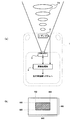
図1(a)は、実施形態のシステム構成図である。車両1(以下「自車1」という。)は、レーザレーダ2(レーダ)と、CMOSカメラ3(撮像デバイス)と、画像処理部4(第一の明度値検出手段、第二の明度値検出手段、先行車認識用画像生成手段、白線認識用画像生成手段)とを備えている。なお、先行車追尾システムとは、たとえば、特開平8−285941号公報などに記載されているように、先行車情報(先行車までの距離や位置、速度などの情報)に基づいて、自車のエンジン出力(場合によっては制動力)や操舵量を加減しながら、先行車の後を追随するように制御するシステムのことをいう。
FIG. 1A is a system configuration diagram of the embodiment. A vehicle 1 (hereinafter referred to as “
レーザレーダ2は、自車1の前方に設定された可変又は固定の監視エリアを、ペンシルビーム形状のレーザビーム2aで満遍なく走査(水平走査と垂直走査)し、監視エリア内の物体からのレーザビーム2aの反射波を受信した時のビーム走査角度(水平角度と垂直角度)から物体の位置(方位と仰角)を割り出すと共に、ビームの発射と反射波受信の時間差から物体までの距離を割り出すものである。なお、レーザの代わりに無線電波を用いたもの、たとえば、ミリ波レーダなどであってもよい。要は、電磁波を媒体として監視エリア内の物体の位置や距離を測定できる測距装置であればよい。
The
CMOSカメラ3は、自車1の前方に設定された監視エリア(レーザレーダ2の監視エリアと同じもの、又は、レーザレーダ2の監視エリアを包含するもの)を光学的に撮影してその画像信号を出力するものであり、このCMOSカメラ3は、少なくとも、屋外撮影における所要ダイナミックレンジ(100dB以上)を満たす性能を有しているとともに、任意領域の画像の選択的読み出し(ランダムアクセス)も可能とするものである。なお、“任意領域の画像の選択的読み出し”とは、CMOSカメラに対して、その有効画素の任意のアドレス範囲(行アドレスと列アドレス)を指定することにより、当該アドレス範囲の画像だけを選択的に取り出すことをいう。
The CMOS camera 3 optically captures a monitoring area (the same as the monitoring area of the
図1(b)は、CMOSカメラにおけるランダムアクセスの概念図である。今、有効画素数を便宜的に640(列)×480(行)画素とするCMOSカメラを例にすると、この場合、たとえば、行アドレスの160〜320の範囲と、列アドレスの160〜480の範囲とを読み出しアドレスとして指定すれば、全画面(640×480)のほぼ中央部分の画像(ハッチング部分)のみを取り出すことができる。このようなランダムアクセス(任意領域の画像の選択的読み出し)は、CMOSカメラの特徴の一つであり、言い換えれば、フォトダイオード等の電荷結合素子に蓄積された電荷を順次に転送するCCDカメラにはない優れた特徴である。 FIG. 1B is a conceptual diagram of random access in a CMOS camera. For example, in this case, for example, a CMOS camera in which the number of effective pixels is 640 (column) × 480 (row) pixels is taken as an example. In this case, for example, a range of 160 to 320 of row addresses and 160 to 480 of column addresses are used. If the range is designated as a read address, only the image (hatched portion) of the substantially central portion of the entire screen (640 × 480) can be extracted. Such random access (selective readout of an image in an arbitrary area) is one of the features of a CMOS camera. In other words, it is applied to a CCD camera that sequentially transfers charges accumulated in a charge coupled device such as a photodiode. There are no excellent features.
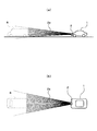
図2は、CMOSカメラ3の撮像範囲を示す図である。CMOSカメラ3は、自車1の前方の監視エリアを、所定の垂直画角φaと所定の水平画角φbの最大撮影可能範囲(ランダムアクセスの最大値)内の任意の大きさで撮像し、その画像信号を毎秒数十フレームの動画像として出力する。垂直画角φaと水平画角φbは、少なくとも、自車1の前方を走行中の車両5(物体)と、路面上の白線6とを撮影可能な適切な値に設定されている。なお、この値(φaとφb)は固定値であってもよく、又は、車速等に応じて変化する可変値であってもよい。
FIG. 2 is a diagram illustrating an imaging range of the CMOS camera 3. The CMOS camera 3 images the monitoring area in front of the
図3及び図4は、レーザレーダ2のスキャン(走査)範囲を示す図である。図3は、先行車5を検出するときのもの、図4は、路面(白線6)を検出するときのものである。先行車5を検出する場合は、レーザビーム2aの仰角(チルト角)中心をほぼ水平にして上下左右を二次元スキャンする。また、路面を検出する場合は、レーザビーム2aの仰角中心を俯角(マイナス角)にして水平方向に一次元スキャンする(又は上下幅のみを狭くして二次元スキャンしてもよい)。
3 and 4 are diagrams showing a scan (scanning) range of the
画像処理部4は、CMOSカメラ3から出力された画像信号を所定のアルゴリズムに従って処理するものであり、そのアルゴリズムの詳細は後述するが、概略的には、レーザレーダ2のスキャン制御とCMOSカメラ3のランダムアクセス制御とを適宜に行うと共に、そのランダムアクセス範囲の画像信号の中から不要な明度情報を除去して情報量を削減した画像信号(後述の「先行車認識用画像」と「白線認識用画像」)を生成し、その情報量を削減した画像信号を先行車追尾システムに出力することにより、当該システムの動作速度の向上(リアルタイム性の向上)を図るというものである。
The image processing unit 4 processes the image signal output from the CMOS camera 3 in accordance with a predetermined algorithm. The details of the algorithm will be described later, but generally, the scan control of the
図5は、画像処理部4の概念構成図である。この図において、画像処理部4は、特にそれに限定しないが、CPU4a、ROM4b、RAM4c及び入出力部4dなどからなるマイクロプログラム制御方式の構成を有している。このような構成の画像処理部4は、ROM4bに予め書き込まれている制御プログラム等のソフトウェアリソースをRAM4cにロードし、それをCPU4aで実行することにより、当該ソフトウェアリソースと、CPU4aなどのハードウェアリソースとの有機的結合によって所望の機能を実現する。
FIG. 5 is a conceptual configuration diagram of the image processing unit 4. In this figure, the image processing unit 4 is not particularly limited, but has a configuration of a microprogram control system including a
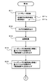
図6及び図7は、画像処理部4で実行されるソフトウェアリソースの概略的なフローチャートを示す図である。このフローチャートでは、まず、レーザレーダ2の二つのスキャン制御を実行する(ステップS11)。第一のスキャン制御(ステップS11a)は、自車1の前方の物体(先行車の車両やその他の物体)を検出するためのものであり(図3参照)、この制御によって自車1の前方に存在する車両等の物体の検出情報(距離等)を取得する。第二のスキャン制御(ステップS11b)は、路面を検出するためのものであり(図4参照)、この制御によって自車1の前方直近の路面の検出情報(距離等)を取得する。
6 and 7 are diagrams illustrating schematic flowcharts of software resources executed by the image processing unit 4. In this flowchart, first, two scan controls of the
次いで、CMOSカメラ3の画像情報(この段階では全画面の画像情報)を取得する(ステップS12)。
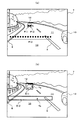
図8は、CMOSカメラ3の画像情報を示す図である。同図(a)は元画像であり、同図(b)は元画像を単純化したものである。これらの図において、画像7は、CMOSカメラ3の全画面の画像情報(CMOSカメラ3のすべての有効画素で構成された画像情報)である。この画像7には様々な被写体、たとえば、白線8、9で仕切られた自車1の走行レーン10(路面)とその右側の隣接レーン11、走行レーン10や隣接レーン11を走行中の車両12、13などが写し込まれている。なお、車両12、13のうち自車1と同じ走行レーン10を走行中の車両12のことを、特にその動きに注意を払わなければならない「先行車」という。
Next, image information of the CMOS camera 3 (image information of the entire screen at this stage) is acquired (step S12).
FIG. 8 is a diagram showing image information of the CMOS camera 3. FIG. 4A is an original image, and FIG. 4B is a simplified version of the original image. In these drawings, an
図9(a)は、レーザレーダ2の検出情報を示す図である。この図において、画像7の上に重畳表示された複数の黒丸印(P11〜P13)は、それぞれレーザレーダ2の検出情報を便宜的に表している。たとえば、P11とP12は、前記の第一のスキャン制御(図3参照)によって検出された先行車12の検出情報を表し、P13は、前記の第二のスキャン制御(図4参照)によって検出された路面情報(白線情報を含む)を表している。
FIG. 9A is a diagram showing detection information of the
さて、この図においては、画像7の上に各々の検出情報(P11〜P13)を重畳表示しているが、実際上は、レーザレーダ2とCMOSカメラ3の座標が同一でないため、レーザレーダ2の検出情報(P11〜P13)とCMOSカメラ3の画像情報との対応を取るために、いずれか一方の座標を基準に他方の座標を変換する必要がある(ステップS13)。図9(a)に示されている検出情報(P11〜P13)の重畳表示は、座標変換した後のものである。
In this figure, the detection information (P11 to P13) is superimposed and displayed on the
このように座標変換を実行した後は、次に、検出情報(P11〜P13)に基づく画像7の切り出しを行う(ステップS14及びステップS15)。ここで、“切り出し”とは、画像7の特定部分を切り出すことをいう。この切り出しは、CMOSカメラ3のランダムアクセスで行ってもよく、又は、画像7はRAM4cに展開されているので、そのRAM4cの所望アドレス範囲の選択的読み出しで行ってもよい。
After executing the coordinate transformation in this way, next, the
図9(b)は、ステップS14及びステップS15における画像7の切り出しの概念図である。この図において、画像7の中に描かれている矩形E11、E12は、それぞれレーザレーダ2の検出情報(P11〜P13)を中心にして生成された切り出し範囲であり、それらの矩形E11、E12に囲まれた部分が、CMOSカメラ3からのランダムアクセスによって、又は、RAM4cに展開された画像7からの選択的読み出しによって切り出される。ここで、矩形E11は、先行車12の検出情報P11、P12に対応するもの、矩形E12は、路面の検出情報P13に対応するものである。以下、矩形E11を用いて切り出された画像のことを「物体画像7a」といい、また、矩形E12を用いて切り出された画像のことを「路面画像7b」ということにする。
FIG. 9B is a conceptual diagram of cutting out the
このように物体画像7aと路面画像7bの切り出しを行うと、次に、それらの物体画像7aと路面画像7bの最低明度値と最高明度値を検出する(ステップS16及びステップS17:第一及び第二の明度値検出工程)。ここで、最低明度値とは当該画像内の各画素の明度情報のうちもっとも暗い値を持つものであり、また、最高明度値とは当該画像内の各画素の明度情報のうちもっとも明るい値を持つものである。以下、物体画像7aの最低明度値をGa_Bmin、最高明度値をGa_Bmaxで表し、また、路面画像7bの最低明度値をGb_Bmin、最高明度値をGb_Bmaxで表すことにする。
When the
このように、物体画像7aと路面画像7bの最低明度値(Ga_Bmin、Gb_Bmin)及び最高明度値(Ga_Bmax、Gb_Bmax)を検出すると、次に、不要な明るさ情報を削減した「先行車認識用画像」と「白線認識用画像」を生成し、それらの画像を先行車追尾システムへ出力(ステップS18及びステップS19:先行車認識用画像生成工程及び白線認識用画像生成工程)して、フローチャートを終了する。
As described above, when the minimum brightness values (Ga_Bmin, Gb_Bmin) and the maximum brightness values (Ga_Bmax, Gb_Bmax) of the
ここで、“不要な明るさ情報”とは、物体画像7aにあっては、Ga_Bmin以下とGa_Bmax以上の明るさ情報のことをいい、また、路面画像7bにあっては、Gb_Bmin以下とGb_Bmax以上の明るさ情報のことをいう。これらの明るさ情報は、先行車の認識や白線の認識に不必要な情報であり、先行車追随システムにおいて、無駄な画像処理の原因となる情報である。
Here, “unnecessary brightness information” refers to brightness information of Ga_Bmin or less and Ga_Bmax or more in the
したがって、本実施形態によれば、先行車の認識や白線の認識に必要な情報のみで構成された画像(先行車認識用画像と白線認識用画像)を先行車追随システムに与えることができるので、当該システムの動作速度を改善し、即応性(リアルタイム性)の向上を図ることができる。 Therefore, according to the present embodiment, the preceding vehicle following system can be provided with an image (an image for recognizing the preceding vehicle and an image for recognizing the white line) configured only with information necessary for the recognition of the preceding vehicle and the recognition of the white line. Thus, the operating speed of the system can be improved, and the quick response (real time performance) can be improved.
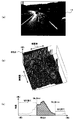
図10は、前記の明るさ情報の削除を行わない場合のCMOSカメラ3の画像14を示す参考図である。(a)は画像14を示し、(b)は画像14の明るさ情報の三次元マップ、(c)は画像14の明るさ情報のヒストグラムを示している。三次元マップの“山”は明度の高い(明るい)部分であり、“谷”は明度の低い(暗い)部分である。また、ヒストグラムの波形はそれぞれの明度値の出現頻度を表しており、ヒストグラムの横軸の長さはCMOSカメラ3のダイナミックレンジに相当する。前記の明るさ情報の削除を行わない場合、先行車追随システムは、図示の画像14に含まれている大量の情報をすべて処理しなければならず、当該システムの処理負担は相当大きい。
FIG. 10 is a reference diagram showing an
これに対して、図11及び図12は、前記の明るさ情報の削除を行った場合のCMOSカメラ3の画像15、16を示す図である。図11に示す画像15は、Ga_Bmin以下とGa_Bmax以上の明るさ情報を削除したもの、図12に示す画像16は、Gb_Bmin以下とGb_Bmax以上の明るさ情報を削除したものである。つまり、画像15はステップS18における「先行車認識用画像」に相当し、画像16はステップS19における「白線認識用画像」に相当する。
On the other hand, FIG.11 and FIG.12 is a figure which shows the
これらの二つの画像15、16(先行車認識用画像と白線認識用画像)のヒストグラムを見ると、前者の画像15(先行車認識用画像)は、Ga_BminからGa_Bmaxまでの特定範囲の明るさ情報しか含んでいない。同様に、後者の画像16(白線認識用画像)も、Gb_BminからGb_Bmaxまでの特定範囲の明るさ情報しか含んでいない。
Looking at the histograms of these two
つまり、前者の画像15(先行車認識用画像)は、元画像(図10の画像14)のGa_Bmin以下とGa_Bmax以上の明るさ情報を切り捨てた画像であり、且つ、後者の画像16(白線認識用画像)も、元画像(図10の画像14)のGb_Bmin以下とGb_Bmax以上の明るさ情報を切り捨てた画像であるから、これらの二つの画像15、16(先行車認識用画像と白線認識用画像)の情報量は、明らかに、元画像(図10の画像14)のそれよりも少ない。
That is, the former image 15 (preceding vehicle recognition image) is an image obtained by discarding brightness information of Ga_Bmin or less and Ga_Bmax or more of the original image (
したがって、本実施形態によれば、これらの二つの画像15、16(先行車認識用画像と白線認識用画像)を処理する先行車追随システムの処理負担を大幅に軽減することができ、当該システムの動作速度を改善し、即応性(リアルタイム性)の向上を図ることができるのである。
Therefore, according to the present embodiment, the processing load of the preceding vehicle tracking system that processes these two
また、図11や図12に示す先行車認識用画像と白線認識用画像(前記の明るさ情報の削除を行った場合のCMOSカメラ3の画像15、16)の例は、CMOSカメラ3の全画面であるが、これに限らず、CMOSカメラ3をランダムアクセスして所望の範囲の画像を選択的に取得し、それらの選択画像をそれぞれ先行車認識用画像と白線認識用画像としてもよい。この場合のランダムアクセス範囲は、たとえば、図9(b)の矩形E11、E12を利用して指定することができる。
Further, examples of the preceding vehicle recognition image and the white line recognition image (
このようにランダムアクセスも併用すると、先行車認識用画像と白線認識用画像の画像サイズを必要最小限の大きさにして画素数を減らすことができ、前記の明るさ情報の削除と相まって、より一層、先行車追随システムの即応性(リアルタイム性)の向上を図ることができるから好ましい。 If random access is also used in this way, the number of pixels can be reduced by reducing the image size of the preceding vehicle recognition image and the white line recognition image to the minimum necessary size, coupled with the deletion of the brightness information, Further, it is preferable because the responsiveness (real-time property) of the preceding vehicle following system can be improved.
Ga_Bmin 最低明度値
Ga_Bmax 最高明度値
Gb_Bmin 最低明度値
Gb_Bmax 最高明度値
S16 ステップ(第一の明度値検出工程)
S17 ステップ(第二の明度値検出工程)
S18 ステップ(先行車認識用画像生成工程)
S19 ステップ(白線認識用画像生成工程)
1 自車
2 レーザレーダ(レーダ)
3 CMOSカメラ(撮像デバイス)
4 画像処理部(第一の明度値検出手段、第二の明度値検出手段、先行車認識用画像生成手段、白線認識用画像生成手段)
5 車両(物体)
7 画像
7a 物体画像
7b 路面画像
10 走行レーン(路面)
14 画像
15 先行車認識用画像
16 白線認識用画像
Ga_Bmin minimum brightness value Ga_Bmax maximum brightness value Gb_Bmin minimum brightness value Gb_Bmax maximum brightness value S16 step (first brightness value detection process)
S17 step (second brightness value detection step)
S18 step (image generation process for preceding vehicle recognition)
S19 Step (Image generation process for white line recognition)
1
3 CMOS camera (imaging device)
4 Image processing unit (first brightness value detection means, second brightness value detection means, preceding vehicle recognition image generation means, white line recognition image generation means)
5 Vehicle (object)
7
14
Claims (4)
前記レーダによって検出された自車前方の物体の検出情報に従って、前記自車前方の画像の中から当該物体を含む物体画像を取り出し、その物体画像の最低明度値と最高明度値とを検出する第一の明度値検出手段と、
前記レーダによって検出された自車前方直近の路面の検出情報に従って、前記自車前方の画像の中から当該路面を含む路面画像を取り出し、その路面画像の最低明度値と最高明度値とを検出する第二の明度値検出手段と、
前記自車前方の画像の明るさ情報のうち前記物体画像の最低明度値以下と最高明度値以上の情報を切り捨てたものを前記先行車認識用画像として生成する先行車認識用画像生成手段と、
前記自車前方の画像の明るさ情報のうち前記路面画像の最低明度値以下と最高明度値以上の情報を切り捨てたものを前記白線認識用画像として生成する白線認識用画像生成手段と
を備えたことを特徴とする画像処理装置。 Based on the detection information from the radar that detects the object in front of the host vehicle and the road surface in front of the host vehicle, the preceding vehicle recognition image and the road surface in front of the host vehicle among the images in front of the host vehicle captured by the imaging device In the image processing apparatus that extracts the white line recognition image above,
According to the detection information of the object ahead of the host vehicle detected by the radar, an object image including the object is extracted from the image ahead of the host vehicle, and a minimum brightness value and a maximum brightness value of the object image are detected. A lightness value detection means;
In accordance with the detection information of the road surface immediately in front of the host vehicle detected by the radar, a road surface image including the road surface is extracted from the image ahead of the host vehicle, and the minimum brightness value and the maximum brightness value of the road image are detected. A second brightness value detecting means;
Preceding vehicle recognition image generation means for generating, as the preceding vehicle recognition image, information obtained by discarding information below the minimum brightness value and the maximum brightness value of the object image among the brightness information of the image ahead of the host vehicle;
White line recognition image generating means for generating, as the white line recognition image, information obtained by discarding information below the minimum brightness value and the maximum brightness value of the road surface image among the brightness information of the image ahead of the vehicle. An image processing apparatus.
前記レーダによって検出された自車前方の物体の検出情報に従って、前記自車前方の画像の中から当該物体を含む物体画像を取り出し、その物体画像の最低明度値と最高明度値とを検出する第一の明度値検出工程と、
前記レーダによって検出された自車前方直近の路面の検出情報に従って、前記自車前方の画像の中から当該路面を含む路面画像を取り出し、その路面画像の最低明度値と最高明度値とを検出する第二の明度値検出工程と、
前記自車前方の画像の明るさ情報のうち前記物体画像の最低明度値以下と最高明度値以上の情報を切り捨てたものを前記先行車認識用画像として生成する先行車認識用画像生成工程と、
前記自車前方の画像の明るさ情報のうち前記路面画像の最低明度値以下と最高明度値以上の情報を切り捨てたものを前記白線認識用画像として生成する白線認識用画像生成工程と
を含むことを特徴とする画像処理方法。 Based on the detection information from the radar that detects the object in front of the host vehicle and the road surface in front of the host vehicle, the preceding vehicle recognition image in front of the host vehicle and the road surface from among the images in front of the host vehicle captured by the imaging device In the image processing method for extracting the white line recognition image above,
According to the detection information of the object ahead of the host vehicle detected by the radar, an object image including the object is extracted from the image ahead of the host vehicle, and a minimum brightness value and a maximum brightness value of the object image are detected. A brightness value detection process;
In accordance with the detection information of the road surface immediately in front of the host vehicle detected by the radar, a road surface image including the road surface is extracted from the image ahead of the host vehicle, and the minimum brightness value and the maximum brightness value of the road image are detected. A second brightness value detection step;
A preceding vehicle recognition image generating step for generating, as the preceding vehicle recognition image, information obtained by discarding information below the minimum brightness value and the maximum brightness value of the object image among the brightness information of the image ahead of the host vehicle;
A white line recognition image generating step for generating, as the white line recognition image, information obtained by discarding information below the minimum brightness value and the maximum brightness value of the road surface image among the brightness information of the image ahead of the vehicle. An image processing method characterized by the above.
The image processing method according to claim 3, wherein the imaging device is a CMOS camera.
Priority Applications (1)
| Application Number | Priority Date | Filing Date | Title |
|---|---|---|---|
| JP2004094516A JP2005284471A (en) | 2004-03-29 | 2004-03-29 | Image processing apparatus and method |
Applications Claiming Priority (1)
| Application Number | Priority Date | Filing Date | Title |
|---|---|---|---|
| JP2004094516A JP2005284471A (en) | 2004-03-29 | 2004-03-29 | Image processing apparatus and method |
Publications (2)
| Publication Number | Publication Date |
|---|---|
| JP2005284471A true JP2005284471A (en) | 2005-10-13 |
| JP2005284471A5 JP2005284471A5 (en) | 2007-02-15 |
Family
ID=35182810
Family Applications (1)
| Application Number | Title | Priority Date | Filing Date |
|---|---|---|---|
| JP2004094516A Pending JP2005284471A (en) | 2004-03-29 | 2004-03-29 | Image processing apparatus and method |
Country Status (1)
| Country | Link |
|---|---|
| JP (1) | JP2005284471A (en) |
Cited By (6)
| Publication number | Priority date | Publication date | Assignee | Title |
|---|---|---|---|---|
| JP2008130087A (en) * | 2006-11-17 | 2008-06-05 | Alpine Electronics Inc | Target area division method and target area division device |
| JP2009017157A (en) * | 2007-07-04 | 2009-01-22 | Omron Corp | Image processor, method and program |
| CN101794391A (en) * | 2010-03-18 | 2010-08-04 | 中国农业大学 | Greenhouse environment leading line extraction method |
| JP2012080517A (en) * | 2010-10-01 | 2012-04-19 | Young Wee Jay | Image acquisition unit, acquisition method and associated control unit |
| WO2019180948A1 (en) * | 2018-03-23 | 2019-09-26 | 本田技研工業株式会社 | Object recognition device, vehicle, and object recognition method |
| WO2021077863A1 (en) * | 2019-10-25 | 2021-04-29 | 华为技术有限公司 | Terminal message processing method, image recognition method, and apparatuses, medium and system |
Citations (4)
| Publication number | Priority date | Publication date | Assignee | Title |
|---|---|---|---|---|
| JPH09167239A (en) * | 1995-12-18 | 1997-06-24 | Hitachi Ltd | Traveling road surface monitoring device applying image processing and method therefor |
| JPH09264954A (en) * | 1996-03-29 | 1997-10-07 | Fujitsu Ten Ltd | Image processing system using radar |
| JP2002327635A (en) * | 2001-04-27 | 2002-11-15 | Nissan Motor Co Ltd | Vehicular running control device |
| JP2003216949A (en) * | 2002-01-18 | 2003-07-31 | Honda Motor Co Ltd | Infrared image processor |
-
2004
- 2004-03-29 JP JP2004094516A patent/JP2005284471A/en active Pending
Patent Citations (4)
| Publication number | Priority date | Publication date | Assignee | Title |
|---|---|---|---|---|
| JPH09167239A (en) * | 1995-12-18 | 1997-06-24 | Hitachi Ltd | Traveling road surface monitoring device applying image processing and method therefor |
| JPH09264954A (en) * | 1996-03-29 | 1997-10-07 | Fujitsu Ten Ltd | Image processing system using radar |
| JP2002327635A (en) * | 2001-04-27 | 2002-11-15 | Nissan Motor Co Ltd | Vehicular running control device |
| JP2003216949A (en) * | 2002-01-18 | 2003-07-31 | Honda Motor Co Ltd | Infrared image processor |
Cited By (10)
| Publication number | Priority date | Publication date | Assignee | Title |
|---|---|---|---|---|
| JP2008130087A (en) * | 2006-11-17 | 2008-06-05 | Alpine Electronics Inc | Target area division method and target area division device |
| JP2009017157A (en) * | 2007-07-04 | 2009-01-22 | Omron Corp | Image processor, method and program |
| CN101794391A (en) * | 2010-03-18 | 2010-08-04 | 中国农业大学 | Greenhouse environment leading line extraction method |
| CN101794391B (en) * | 2010-03-18 | 2011-12-28 | 中国农业大学 | Greenhouse environment leading line extraction method |
| JP2012080517A (en) * | 2010-10-01 | 2012-04-19 | Young Wee Jay | Image acquisition unit, acquisition method and associated control unit |
| WO2019180948A1 (en) * | 2018-03-23 | 2019-09-26 | 本田技研工業株式会社 | Object recognition device, vehicle, and object recognition method |
| JPWO2019180948A1 (en) * | 2018-03-23 | 2021-01-14 | 本田技研工業株式会社 | Object recognition device, vehicle and object recognition method |
| JP7060676B2 (en) | 2018-03-23 | 2022-04-26 | 本田技研工業株式会社 | Object recognition device, vehicle and object recognition method |
| US11935308B2 (en) | 2018-03-23 | 2024-03-19 | Honda Motor Co., Ltd. | Object recognition apparatus, vehicle, and object recognition method |
| WO2021077863A1 (en) * | 2019-10-25 | 2021-04-29 | 华为技术有限公司 | Terminal message processing method, image recognition method, and apparatuses, medium and system |
Similar Documents
| Publication | Publication Date | Title |
|---|---|---|
| US7522747B2 (en) | Vehicle detection apparatus and method | |
| JP4157620B2 (en) | Moving object detection apparatus and method | |
| US9596407B2 (en) | Imaging device, with blur enhancement | |
| TWI821417B (en) | Sensor device and signal processing method | |
| KR100947002B1 (en) | Image processing method and apparatus, digital camera, and recording medium recording image processing program | |
| CN111462503B (en) | Vehicle speed measuring method and device and computer readable storage medium | |
| KR101553589B1 (en) | Appratus and method for improvement of low level image and restoration of smear based on adaptive probability in license plate recognition system | |
| JP4386959B1 (en) | Image processing device | |
| CN111144156B (en) | Image data processing method and related device | |
| JP2005284471A (en) | Image processing apparatus and method | |
| Yamada et al. | A vision sensor having an expanded dynamic range for autonomous vehicles | |
| KR20140026078A (en) | Apparatus and method for extracting object | |
| JPH11278182A (en) | Fog status detection device for vehicle | |
| JP4437532B2 (en) | Imaging apparatus and image processing method | |
| JP2006318061A (en) | Apparatus, method, and program for image processing | |
| KR102445008B1 (en) | Apparatus and Method for Sensing Image based on Event | |
| JP6825299B2 (en) | Information processing equipment, information processing methods and programs | |
| WO2022145054A1 (en) | Image processing device, image processing method, and recording medium | |
| JP2018055591A (en) | Information processing apparatus, information processing method and program | |
| JP6826472B2 (en) | Image processing device and its control method | |
| JP4355305B2 (en) | Image processing apparatus, computer program, and recording medium | |
| JP3479601B2 (en) | Method and apparatus for reading characters in landscape image and recording medium recording the method | |
| CN115086558B (en) | Focusing method, image pickup apparatus, terminal apparatus, and storage medium | |
| WO2022107636A1 (en) | Image recognition device, learning system, image storage device, image recognition method, image storage method, and recording medium | |
| JP6669062B2 (en) | Image processing device |
Legal Events
| Date | Code | Title | Description |
|---|---|---|---|
| A521 | Request for written amendment filed |
Free format text: JAPANESE INTERMEDIATE CODE: A523 Effective date: 20061227 |
|
| A621 | Written request for application examination |
Free format text: JAPANESE INTERMEDIATE CODE: A621 Effective date: 20061227 |
|
| A131 | Notification of reasons for refusal |
Free format text: JAPANESE INTERMEDIATE CODE: A131 Effective date: 20091222 |
|
| A02 | Decision of refusal |
Free format text: JAPANESE INTERMEDIATE CODE: A02 Effective date: 20100430 |