JP2005282979A - Air conditioner for toilet - Google Patents
Air conditioner for toilet Download PDFInfo
- Publication number
- JP2005282979A JP2005282979A JP2004098946A JP2004098946A JP2005282979A JP 2005282979 A JP2005282979 A JP 2005282979A JP 2004098946 A JP2004098946 A JP 2004098946A JP 2004098946 A JP2004098946 A JP 2004098946A JP 2005282979 A JP2005282979 A JP 2005282979A
- Authority
- JP
- Japan
- Prior art keywords
- air conditioner
- air
- dehumidifying
- toilet
- heating
- Prior art date
- Legal status (The legal status is an assumption and is not a legal conclusion. Google has not performed a legal analysis and makes no representation as to the accuracy of the status listed.)
- Pending
Links
Images


Abstract
Description
本発明は、便器に水を勢いよく流して洗う水洗トイレ、トイレ室内あるいは人体等を冷房または暖房するトイレ用空調装置に関するものである。 The present invention relates to a flush toilet that flushes and flushes toilets, and a toilet air conditioner that cools or heats a toilet room or a human body.
従来、この種のトイレ用空調装置は、図22に示すような構成であった。すなわち、冷凍サイクルを構成する圧縮機1、凝縮器2、蒸発器3等を有する空調装置は、トイレ室4の壁に設け、便器5を洗う水を貯めている水タンク6(ロータンク)に凝縮器2を水没させ、圧縮機1、蒸発器3、送風ファン7等は一つのケース8に納めてトイレ室4の壁に設置した構成である(例えば、特許文献1参照)。
Conventionally, this type of toilet air conditioner has a configuration as shown in FIG. That is, the air conditioner having the
そして、圧縮機1の運転により冷媒を凝縮器2、蒸発器3、圧縮機1と循環させ、トイレ室4の空気を送風ファン7により蒸発器3で熱交換させて吹出口9よりトイレ室4に冷風を送り空調するとともに、凝縮器2の凝縮熱は水タンク6の水に放熱してトイレ室4には放出しないように構成している。
しかしながら、前記従来のトイレ用空調装置では、凝縮器2は水タンク6内に、圧縮機1、蒸発器3、送風ファン7等はケース8内にそれぞれ設け、そしてケース8を壁に、凝縮器2を水タンク6に別々に取付けることになり、装置が大掛かりなものとなり、かつトイレ室4への設置工事も手間のかかる。また冷房が効き始めるのに時間を要し、短時間で冷涼感を得るのは難しいという課題を有していた。
However, in the conventional toilet air conditioner, the
本発明は、前記従来の課題を解決するもので、装置全体を小型にできるので収納空間を小さくすることができ、安価で装置の簡素化の図れるトイレ用空調装置を提供することを目的とする。 SUMMARY OF THE INVENTION The present invention solves the above-described conventional problems, and an object thereof is to provide a toilet air conditioner that can reduce the size of the entire apparatus, reduce the storage space, and can be simplified at low cost. .
前記従来の課題を解決するために、本発明のトイレ用空調装置は、送風機と、前記送風機で送風された空気を吸着により除湿する除湿手段と、前記除湿手段で除湿された空気を吹出す吹出口と、前記除湿手段を加熱する加熱手段とで構成したものである。 In order to solve the above-mentioned conventional problems, a toilet air conditioner according to the present invention includes a blower, a dehumidifying means for dehumidifying the air blown by the blower by adsorption, and a blower for blowing the air dehumidified by the dehumidifying means. It comprises an outlet and heating means for heating the dehumidifying means.
これによって、運転開始後、除湿空気により人体の汗を気化することで、気化熱潜熱を奪い、短時間で冷涼感が得られて、装置を小型にでき、構成が簡素とすることができるので、安価でしかも収納空間の小さいものにすることができる。 As a result, after the start of operation, the sweat of the human body is vaporized with dehumidified air, thereby removing the latent heat of vaporization, providing a cool feeling in a short time, making the device compact, and simplifying the configuration. It can be made inexpensive and small in storage space.
本発明のトイレ用空調装置は、冷凍サイクルを構成する圧縮機、凝縮器、蒸発器を有する装置に比べ、装置を小型で安価にでき、構成も簡素とすることができる。また、構成部品自体が小さく、部品点数も少ないため、収納空間が小さくなり、小空間に収納設置することができる。 The toilet air conditioner of the present invention can be made smaller and less expensive and the configuration can be simplified as compared with a device having a compressor, a condenser, and an evaporator constituting a refrigeration cycle. In addition, since the component parts themselves are small and the number of parts is small, the storage space is reduced, and can be stored and installed in a small space.
また、人体が汗をかいた際に、除湿された空気を吹付けて、気化潜熱で冷涼感が得られ、汗が引くと、必要以上に人体を冷やし過ぎることがないので、低温風を吹き付けられて感じる不快感はない。 In addition, when the human body sweats, the dehumidified air is blown and a cool feeling is obtained by the latent heat of vaporization, and if the sweat is pulled, the human body will not be cooled more than necessary, so low-temperature air is blown. There is no discomfort felt.
また、除湿手段の除湿性能を回復していれば、送風機を動作させて除湿手段に空気を送り込むだけで、除湿された空気とすることができるので、使用者は気化潜熱を奪われて、即効して冷涼感が得られる。 In addition, if the dehumidifying performance of the dehumidifying means has been restored, it can be made dehumidified air by simply operating the blower and sending air to the dehumidifying means. A cool feeling is obtained.
第1の発明は、送風機と、前記送風機で送風された空気を吸着により除湿する除湿手段と、前記除湿手段で除湿された空気を吹出す吹出口と、前記除湿手段を加熱する加熱手段とを備えたものである。そして、除湿された空気が吹出口より吹き出て、人体に吹きつけられると、汗が気化乾燥し、気化熱を皮膚表面から奪い、夏季のトイレ室内の温度が上昇している場合でも、冷涼感を感じさせ、汗のむれ感を解消して使用時は快適に用を足すことができる。 The first invention includes a blower, a dehumidifying means for dehumidifying the air blown by the blower by adsorption, a blowout port for blowing out the air dehumidified by the dehumidifying means, and a heating means for heating the dehumidifying means. It is provided. And when the dehumidified air blows out from the outlet and is blown to the human body, sweat evaporates and dries, removes the heat of vaporization from the skin surface, and even when the temperature in the toilet room in the summer is rising, You can feel the sensation and eliminate the feeling of sweating.
例えば、トイレ室内空気を吸い込んで人体を除湿して冷涼感を得る除湿運転では、送風機によって除湿手段に送り込まれたトイレ室内の空気は、吸着材で水蒸気を吸着され湿度が低下するとともに吸着熱で発熱し高温除湿空気となる。高温除湿空気を人体に吹き当てるように吹出口より吹き出され、人体背側面を流れる。その際体表面の汗を気化させることで気化熱をうばい人体に冷涼感を与えるとともに、ムレ感をも防止する。 For example, in a dehumidifying operation that sucks toilet room air and dehumidifies the human body to obtain a cool feeling, the air in the toilet room sent to the dehumidifying means by the blower is adsorbed with water vapor by the adsorbent, reducing the humidity and absorbing heat. It generates heat and becomes high-temperature dehumidified air. It is blown out from the air outlet so that high-temperature dehumidified air is blown against the human body, and flows on the back side of the human body. At that time, the sweat on the surface of the body is vaporized to give a cool feeling to the human body and to prevent the feeling of stuffiness.
また、除湿運転は、除湿手段が再生されていれば送風機の電力だけで実行されので、消費電力が低減される。さらに、50から60%RH以下の低湿度では、結露させて除湿する方式に比べ、除湿性能が高くなり、気化熱を皮膚表面からより多く奪い、より冷却感を感じさせ、汗のむれ感を解消して使用者はより快適に用を足すことができる。 Further, since the dehumidifying operation is executed only with the power of the blower if the dehumidifying means is regenerated, the power consumption is reduced. Furthermore, at low humidity of 50 to 60% RH or less, the dehumidifying performance is higher than the method of dehumidifying by dew condensation, and more heat from vaporization is taken away from the skin surface, making it feel cooler and feeling sweaty. The user can use it more comfortably.
また、除湿手段を加熱する加熱手段を備えているので、湿気を吸着した除湿手段を加熱することにより、水分を放出させて、再び除湿可能な状態に回復させることができる。そして、除湿と再生を繰り返すことにより、除湿手段を交換することなく、半永久的に使用することができる。また、除湿手段の吸着能力を最大限に引き出した状態でトイレ用空調装置を運転できる。しかも除湿手段における結露水の処理も必要ない。 Further, since the heating means for heating the dehumidifying means is provided, by heating the dehumidifying means that has adsorbed the moisture, it is possible to release moisture and restore the dehumidifying state again. By repeating dehumidification and regeneration, the dehumidifying means can be used semi-permanently without replacement. Further, the toilet air conditioner can be operated in a state where the adsorption capacity of the dehumidifying means is maximized. Moreover, there is no need for the treatment of condensed water in the dehumidifying means.
なお、除湿手段をハニカム状の円盤型として回転させ除湿と再生を繰り返す回転ドラム方式や、再生と吸着を繰り返すバッチ方式としても同様の効果を実現できるのは、いうまでもない。 Needless to say, the same effect can be realized by a rotating drum system in which the dehumidifying means is rotated as a honeycomb-shaped disk and the dehumidification and regeneration are repeated, and a batch system in which the regeneration and adsorption are repeated.
第2の発明は、前記除湿手段で除湿された空気を冷却する熱交換器を備えた構成としたものである。除湿手段に送り込まれた空気は吸着材で水蒸気を吸着され湿度が低下するとともに吸着熱で発熱し高温除湿空気となるが、熱交換器を通過した際に熱交換が行われて冷却されるので、人体に吹き当てるように吹出口より吹き出されると、吹出温度が低くなるため、より冷涼感を得ることができる。 2nd invention is set as the structure provided with the heat exchanger which cools the air dehumidified by the said dehumidification means. The air sent to the dehumidifying means adsorbs water vapor with the adsorbent and lowers the humidity and generates heat due to the adsorption heat to become high-temperature dehumidified air, but since it is cooled by heat exchange when passing through the heat exchanger, If the air is blown out from the air outlet so as to be blown against the human body, the air temperature is lowered, so that a cooler feeling can be obtained.
第3の発明は、前記熱交換器を冷却する冷却ファンを備えた構成としたものである。熱交換器は冷却ファンによって冷却されるので、吸着手段で発生する吸着熱は熱交換器に溜まることなく、熱交換器に溜まった熱を強制的に冷却ファンによって廃熱させるので、急速かつ効率的に冷却作用を持続して行うことができる。 3rd invention is set as the structure provided with the cooling fan which cools the said heat exchanger. Since the heat exchanger is cooled by a cooling fan, the heat of adsorption generated by the adsorbing means does not accumulate in the heat exchanger, and the heat accumulated in the heat exchanger is forcibly discarded by the cooling fan. Thus, the cooling action can be continuously performed.
第4の発明は、前記熱交換器はロータンクの水により冷却されるものである。 In a fourth invention, the heat exchanger is cooled by water in a low tank.
そして、熱交換器はロータンクの水により冷却されるので、吸着手段で発生する吸着熱は熱交換器に溜まることなく、熱交換器に溜まった熱を強制的にロータンク内の水によって冷却されるので、急速かつ効率的に冷却作用を持続して行うことができる。 Since the heat exchanger is cooled by the water in the raw tank, the heat of adsorption generated by the adsorption means does not accumulate in the heat exchanger, and the heat accumulated in the heat exchanger is forcibly cooled by the water in the raw tank. Therefore, the cooling operation can be performed rapidly and efficiently.
第5の発明は、ペルチェ素子で熱交換器を冷却することにより、熱交換器にペルチェ素子の吸熱面を接地させて、廃熱面は送風機で廃熱させることにより熱交換器自体を冷却させることができる。 In the fifth aspect of the invention, the heat exchanger is cooled by the Peltier element, the heat-absorbing surface of the Peltier element is grounded by the heat exchanger, and the waste heat surface is discharged by the blower to cool the heat exchanger itself. be able to.
第6の発明は、前記除湿手段から前記吹出口へ除湿された空気を導く通風路と、前記通風路はロータンク内の水を通り除湿手段で除湿された後の空気を冷却することを特徴としたものである。 A sixth aspect of the invention is characterized in that a ventilation path that guides dehumidified air from the dehumidifying means to the outlet, and the ventilation path passes through water in a raw tank and cools the air after being dehumidified by the dehumidifying means. It is a thing.
そして、通風路はロータンクの水と接触しているため、通風路内を除湿された空気が通過する際にロータンク内の水により冷却されて熱交換が行われて、冷却されるので、より冷涼感を得ることができる。 And since the ventilation path is in contact with the water in the low tank, when the dehumidified air passes through the ventilation path, it is cooled by the water in the low tank, heat is exchanged, and is cooled. A feeling can be obtained.
第7の発明は、前記除湿手段を密閉するダンパー等の密閉部を備えたものである。予め加熱手段を動作させ除湿手段から水蒸気を脱離させ、除湿手段を再生する。その後密閉部のダンパーによって除湿手段を密閉しておき、次回の使用時に、密閉部のダンパーを開き、送風機を動作させ、吹出口からすぐに除湿空気を吹出し、人体に吹付けて冷涼感を得ることができる。 7th invention is equipped with sealing parts, such as a damper, which seals the said dehumidification means. The heating means is operated in advance to desorb water vapor from the dehumidifying means, and the dehumidifying means is regenerated. After that, the dehumidifying means is sealed with the damper of the sealed part, and at the next use, the damper of the sealed part is opened, the blower is operated, the dehumidified air is blown out immediately from the outlet, and the human body is blown to obtain a cool feeling be able to.
第8の発明は、前記加熱手段が前記除湿手段を加熱した際に発生する脱着された水分を排出する排出口と、前記排出口の開閉を行う排気切替手段とを備えたものである。
そして、除湿手段を再生する際は、排気切替手段のダンパーを空け、加熱手段を動作させ除湿手段から水蒸気を脱離させ、脱離した水蒸気は排出口から排気する。次に送風機を動作させ、吹出口から吹出し人体に吹付ける。なお、送風機から除湿手段に送られた空気は水蒸気を吸着され湿度が低下するとともに、吸着熱で温度が上昇した除湿空気となり、吹出口から吹出し人体に吹付ける。そして吸着材再生時に発生する水蒸気は排出口から排気され、除湿手段の除湿性能を回復させ、間欠的であるが長時間に亘って、除湿空気を吹出すことができる。
According to an eighth aspect of the invention, there is provided an exhaust port for discharging desorbed moisture generated when the heating unit heats the dehumidifying unit, and an exhaust gas switching unit for opening and closing the exhaust port.
When regenerating the dehumidifying means, the damper of the exhaust gas switching means is opened, the heating means is operated to desorb water vapor from the dehumidifying means, and the desorbed water vapor is exhausted from the discharge port. Next, the air blower is operated and blown out from the air outlet to the human body. The air sent from the blower to the dehumidifying means adsorbs water vapor, lowers the humidity, and becomes dehumidified air whose temperature is increased by the heat of adsorption, and blows out from the blowout outlet to the human body. Then, the water vapor generated during the regeneration of the adsorbent is exhausted from the discharge port to restore the dehumidifying performance of the dehumidifying means, and the dehumidified air can be blown out over an extended period of time.
第9の発明は、前記排出口より吹出される脱着された水分をロータンク内に吹き込むことを特徴としたものである。
除湿手段の除湿性能を回復させる再生モード時に、排気切替手段を開き、排気をロータンク内に吹き込んでロータンク水に結露させて、トイレの室温を上昇させないようにすることができる。
The ninth invention is characterized in that the desorbed water blown from the discharge port is blown into the low tank.
During the regeneration mode in which the dehumidifying performance of the dehumidifying means is restored, the exhaust gas switching means can be opened to blow the exhaust gas into the low tank and condense on the low tank water so that the room temperature of the toilet is not raised.
第10の発明は、加熱手段の表面に吸着材を担持してなる除湿手段としたものである。 The tenth aspect of the invention is a dehumidifying means in which an adsorbent is supported on the surface of the heating means.
加熱手段の表面に吸着材を担持した構成であるため、再生時における吸着材の昇温速度が大きくなる。つまり再生時間を短くしても吸着した大部分の水蒸気が放出されることになる。従って短時間で吸着能力が回復するため断続的に除湿モ−ドと吸着モ−ドを繰り返しても充分な除湿能力を発揮することが出来るため除湿手段を大幅に小型化でき、トイレ用空調装置への組込みが容易となる。 Since the adsorbent is supported on the surface of the heating means, the temperature rise rate of the adsorbent during regeneration is increased. That is, even if the regeneration time is shortened, most of the adsorbed water vapor is released. Therefore, since the adsorption capacity is restored in a short time, the dehumidification means can be exerted even if the dehumidification mode and the adsorption mode are repeated intermittently. Easy integration into
さらに長期放置された場合でも予め吸着材を再生した後、徐々に大気中の水蒸気を吸着するのを防止するための厳重なシ−ル構成が不要となり短時間で除湿能力が発揮できるため構成が簡素化され、更なる小型化を実現することができる。 In addition, even after being left for a long period of time, after regenerating the adsorbent in advance, a strict seal configuration for preventing the gradual adsorption of water vapor in the atmosphere is unnecessary, and the dehumidifying ability can be demonstrated in a short time. Simplified and further miniaturization can be realized.
第11の発明は、前記加熱手段は金属薄板に切れ込み加工を行い伸張させたエキスパンドメタルと、金属線を編んだ金網と、金属薄板に穴加工を施した多孔体のいずれかを有し、前記エキスパンドメタルと前記金網と前記多孔体のいずれかに電流を流して発熱させるものである。エキスパンドメタルや金網や多孔体によって、熱容量の小さい加熱部が実現でき、加熱部の立ち上がりがすばやく、再生時間を短時間かできる。さらに加熱部表面に吸着材を担持した構成では、表面積が大きく、また表面の凹凸で気流が乱され、水蒸気の吸着能力が向上する。また、吸着材を担持する際の密着力が上がり、吸着部の耐久性がより向上する。 In an eleventh aspect of the invention, the heating means includes any one of an expanded metal obtained by cutting and stretching a metal thin plate, a wire mesh knitted with a metal wire, and a porous body in which a hole is formed in the metal thin plate, A current is passed through any one of the expanded metal, the wire mesh, and the porous body to generate heat. The expanded metal, the wire mesh, and the porous body can realize a heating unit with a small heat capacity, and the heating unit can be quickly started and the regeneration time can be shortened. Further, in the configuration in which the adsorbent is supported on the surface of the heating unit, the surface area is large, and the air flow is disturbed by the irregularities on the surface, so that the water vapor adsorption ability is improved. Further, the adhesion force when carrying the adsorbent increases, and the durability of the adsorbing portion is further improved.
第12の発明は、前記加熱手段を通電させて、暖房することを特徴としたものである。加熱手段を連続通電させて、送風機で送風することによって、吹出口から温風が吹出し、人体に吹付けることにより、冬季などトイレ室内が寒い際に暖房することができる。 The twelfth invention is characterized in that heating is performed by energizing the heating means. By continuously energizing the heating means and blowing with a blower, warm air is blown out from the outlet and blown onto the human body, so that the toilet room can be heated when it is cold such as in winter.
以下、本発明の実施の形態について、図面を参照しながら説明する。なお、この実施の形態によって本発明が限定されるものではない。 Hereinafter, embodiments of the present invention will be described with reference to the drawings. Note that the present invention is not limited to the embodiments.
(実施の形態1)
図1は、本発明の実施の形態1におけるトイレ用空調装置の斜視図、図2はトイレ用空調装置の構成を示す斜視図、図3は除湿モードにおけるトイレ用空調装置本体の断面図、図4は再生モードにおけるトイレ用空調装置本体の断面図である。
(Embodiment 1)
1 is a perspective view of a toilet air conditioner according to
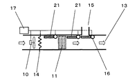
図2において、送風機(以下送風機)10はシロッコファンや軸流ファン等である。除湿手段11は例えばゼオライトやシリカゲルやチタシリケート、活性アルミナ等などの吸着材12を有し、送風機10で送風された空気を除湿する。吹出口13は人体に除湿空気を吹き付ける。また、除湿手段11が水分を吸着したのち再生させるために、除湿手段11を対流、輻射または熱伝導で加熱する加熱する電気抵抗発熱体等の加熱手段14が設けられ、前記加熱手段14が前記除湿手段11を加熱した際に発生する水蒸気は排出口15から排出する構成となっており、吹出口13および排出口15の開閉を可能とする除湿手段11の下流に設けたダンパー等の排気切替手段16と、排気切替手段16や送風機10や加熱手段14の動作を制御する制御手段17とで構成している。
In FIG. 2, a blower (hereinafter referred to as a blower) 10 is a sirocco fan, an axial fan or the like. The dehumidifying means 11 has an adsorbent 12 such as zeolite, silica gel, titasilicate, activated alumina, etc., and dehumidifies the air blown by the
以上のように構成されたトイレ用空調装置について、以下、その動作、作用を説明する。 The operation and action of the toilet air conditioner configured as described above will be described below.
図3に示すように、排気切替手段16を排出口15を閉じる位置に設定し、除湿モード運転時は、送風機10で送風された空気を除湿手段11が除湿する。除湿された空気は除湿手段11から吹出口13に導かれて吹出される。便座には使用者が着座していて、除湿された空気が使用者の首筋や背中や腰部に吹きつけられる。このようにして、人体表面に除湿された空気を吹きつける。このため、汗が気化乾燥し、気化熱を皮膚表面から奪い、夏季にトイレ室内の温度が上昇した状態でも、冷涼感を感じさせ、汗のむれ感を解消して使用者は快適に過ごせる。トイレ室内の空気は例えば35℃、55%RHとした場合、例えば0.2m3/分の流量で送りこまれた空気は、水蒸気を吸着され湿度が低下するとともに吸着熱で発熱し、例えば48℃、18%RHになる。そして、除湿された空気は吹出口13から吹き出し、使用者の背側面を流れる。その際使用者は除湿空気からの熱伝達によって受熱するが、体表面や衣類の汗が急速に気化し多量の気化熱をうばうので人体に冷涼感を与える。また、汗が気化するので皮膚の蒸れ感をも防止する。以上のように、本実施の形態においては、除湿運転は送風機10の電力だけで実行されるので、消費電力が低減される。さらに50〜60%RH以下の低湿度では、結露させて除湿する方式に比べ、除湿性能が高くなり、気化熱を皮膚表面からより多く奪い、より冷涼感を感じさせ、汗のむれ感を解消して使用者はより快適に用を足せる。
As shown in FIG. 3, the exhaust switching means 16 is set to a position where the
また、除湿手段11除湿性能を回復させる再生モード時は、図4に示すように、送風機を停止し、排気切替手段16を排出口15を空ける位置にし、加熱手段14を通電し、シリカゲルの場合は吸着材12を130℃まで加熱し水蒸気を吸着材から放出させ、排出口15から室内に高湿度の空気として放出する。
Further, in the regeneration mode for recovering the dehumidifying performance of the dehumidifying means 11, as shown in FIG. 4, the blower is stopped, the exhaust switching means 16 is set to a position where the
なお、本発明は、装置を小さくできるので、小さな収納空間に収めることができる。したがって、図1のようなロータンク(水タンク)のないトイレや便器に備えられた局部洗浄装置内に本体を収納することが可能である。 In the present invention, since the apparatus can be made small, it can be stored in a small storage space. Therefore, it is possible to store the main body in a local cleaning device provided in a toilet or toilet without a low tank (water tank) as shown in FIG.
なお、加熱手段14を連続通電させて、送風機10を動作させることにより、吹出口13より温風を吹出すことができるので、冬季には、使用者の暖房に利用することもできる。
In addition, since warm air can be blown out from the
(実施の形態2)
図5は本発明の実施の形態2によるトイレ用空調装置本体の断面図、図6はトイレ用空調装置の斜視図、図7は実施の形態2の他の一例を示すトイレ用空調装置の斜視図、図8は他の一例を示すトイレ用空調装置本体の断面図、図9は実施の形態2の他の一例を示すトイレ用空調装置の斜視図、図10は他の一例を示すトイレ用空調装置本体の断面図、である。
(Embodiment 2)
5 is a sectional view of a toilet air conditioner body according to a second embodiment of the present invention, FIG. 6 is a perspective view of the toilet air conditioner, and FIG. 7 is a perspective view of a toilet air conditioner showing another example of the second embodiment. FIG. 8, FIG. 8 is a sectional view of a toilet air conditioner main body showing another example, FIG. 9 is a perspective view of a toilet air conditioner showing another example of
本実施の形態と実施の形態1との違いは、除湿手段11を通過した空気を冷却する熱交換器18設けている点である。
The difference between the present embodiment and the first embodiment is that a
なお、熱交換器18形式は限定しないが、一般的には隔壁にフィンを付けたプレートフィン型熱交換器で室内の空気で温度上昇した除湿空気を熱交換し、冷却する。また、図5に示すように、熱交換器18を冷却する冷却ファン19を設けてもよい。その冷却ファン19の送風量を制御手段17で制御し、発生する熱量に応じて送風量を変化させてもよい。また、熱交換器18と伝熱関係をもつ熱伝導材料を設け、熱交換器18からさらに熱容量の大きい便器やロータンク6などへ熱を移動させてもよい。または熱交換器18より熱容量の大きい蓄熱材料を、熱交換器18と伝熱関係をもつように配してもよい。さらに、ペルチェ素子で熱交換器18を冷却してもよく、ペルチェ素子を挟み込むように片側にフィンを設けたアルミ押出材のベース面を互い重ね合せて、フィンの温度を低下させて、フィンを通過した空気を冷却することができる。また、図7、図8に示すように、ロータンク6の水と熱交換器18を接触させて、熱交換器18を冷却してもよい。また図9、図10に示すように、通風路21自体をロータンク6内の水中に設け、伝熱等により冷却しても熱交換器18と同様の効果をもつ。
The type of
以上のように構成されたトイレ用空調装置について、以下、その動作、作用を説明する。前述のように、送風機10によって除湿手段11に送られた室内の空気は、除湿手段11で水分を吸着され湿度が低下する。それと同時にこの空気は吸着熱で発熱し、48℃、18%RH程度の状態になる。この高温低湿の空気は熱交換器18に導かれ、室内空気で冷却され、例えば37℃、33%RHの低湿空気となる。そして吹出口13から吹き出し、人体背側面を流れる。この場合、人体は除湿空気からの熱伝達が小さくなり、体表面の汗を気化させることで気化熱をうばい人体に冷涼感を与える。
The operation and action of the toilet air conditioner configured as described above will be described below. As described above, the indoor air sent to the dehumidifying means 11 by the
以上のように、本実施の形態においては、温度が変動しないあるいは変動を抑えて乾燥した空気になる。よって、より冷却感を感じさせ、汗のむれ感を解消して快適に用を足せる。 As described above, in the present embodiment, the air does not fluctuate or the air is dried with the fluctuations suppressed. Therefore, the feeling of cooling can be felt more, the feeling of sweating can be eliminated, and it can be used comfortably.
なお、図11のように、排出口15を水タンク内の水面に吹付けるように配置することにより、除湿手段11の除湿性能を回復させる再生モード時に、排気切替手段16を開き、排出口15から除湿手段11より脱着された水蒸気をロータンク内の水面に吹き込んで、ロータンク内の水で冷やし結露させて、さらにトイレ室内の室温を上昇させないようにすることができる。
As shown in FIG. 11, by arranging the
(実施の形態3)
図12、図13、図14は本発明の実施の形態3におけるトイレ用空調装置本体の断面図である。本実施の形態と実施の形態1との違いは、除湿手段11を密閉させる密閉部21を有する点である。送風機10はシロッコファンや軸流ファン等である。除湿手段11は例えばゼオライトやシリカゲルやチタシリケート、活性アルミナ等などの吸着材12を有し、送風機10で送風された空気を除湿する。吹出口13は人体に除湿空気を吹き付ける。また、除湿手段11が水分を吸着したのち再生させるために、除湿手段11を対流、輻射または熱伝導で加熱する電気抵抗発熱体等の加熱手段14が設けられ、前記加熱手段14が前記除湿手段11を加熱した際に発生する水蒸気は排出口15から排出する構成となっており、吹出口13および排出口15の開閉を可能とする除湿手段11の下流に設けたダンパー等の排気切替手段16と、除湿手段11を外気との接触を防ぐダンパー等の密閉を可能とする密閉部22と、排気切替手段16や密閉部22や送風機10や加熱手段14の動作を制御する制御手段17とで構成している。
(Embodiment 3)
12, 13 and 14 are sectional views of a toilet air conditioner main body according to Embodiment 3 of the present invention. The difference between the present embodiment and the first embodiment is that a sealing
以上のように構成されたトイレ用空調装置について、以下、その動作、作用を説明する。図12のように吸着材を内蔵する除湿手段11は実施の形態1と同様の除湿モード運転をする前に、予め、水分を放出させて乾燥させておく必要がある。あるいは、除湿モードでの運転後に、再度使用するためには除湿手段11が吸着した水分を除去する必要がある。このため、水分を放出する脱着温度まで加熱手段14で加温する。そして脱着した水蒸気を含んで高温多湿になった空気は、送風機10による送風により、排出口15から排出される。これにより、除湿手段11の有する吸着材を交換することなく、長期に渡って除湿された空気を吹出口から供給する。また、除湿手段11の吸着能力を最大限に引き出した状態でトイレ用空調装置を運転できる。しかも除湿手段11における結露水の処理も必要ない。
The operation and action of the toilet air conditioner configured as described above will be described below. As shown in FIG. 12, the dehumidifying means 11 containing the adsorbent needs to be dried in advance by releasing moisture before the dehumidifying mode operation similar to that of the first embodiment. Alternatively, after the operation in the dehumidifying mode, it is necessary to remove the moisture adsorbed by the dehumidifying means 11 in order to use again. For this reason, it heats with the heating means 14 to the desorption temperature which discharge | releases a water | moisture content. Then, the air that has become hot and humid, including the desorbed water vapor, is discharged from the
また、図13に示すように、除湿手段11が水分を放出し終えると加熱手段14を停止させ、密閉部21によって除湿手段11が密閉され、待機状態となる。次に除湿運転を行うときには、図14に示すように、密閉部21が開放され、送風機10が室内の空気を乾燥状態になった除湿手段11に送り込む。そして、吹出口13より吹出し、人体表面に除湿された空気を吹きつける。このため、汗が気化乾燥し、気化熱を皮膚表面から奪い、夏季にトイレ室内の温度が上昇した状態でも、冷涼感を感じさせ、汗のむれ感を解消して、使用者は快適に用を足せる。このような構成により、待機状態において、除湿手段11が大気中の水分を吸着し、その除湿能力が低下するのを防ぐので、使用者がトイレを使用する際に、即効して冷涼感を得ることができる。
Further, as shown in FIG. 13, when the dehumidifying means 11 finishes releasing moisture, the heating means 14 is stopped, and the dehumidifying means 11 is sealed by the sealing
(実施の形態4)
図15、図16は本発明の実施の形態4におけるトイレ用空調装置本体の断面図、図15は除湿モードにおけるトイレ用空調装置本体の断面図、図16は再生モードにおけるトイレ用空調装置本体の断面図で、図17は除湿手段の斜視図、図18は除湿手段の断面図ある。なお実施の形態1と同一符号のものは同一構造を有し、説明は省略する。本発明では、実施の形態1のトイレ用空調装置において、除湿手段11を、帯形状の電気抵抗発熱体をプリーツ加工した加熱手段14の表面に吸着材12を担持し、帯形状の電気抵抗発熱体の端部全面に接触するように溶接した端子22に通電させて発熱させる構成としたものである。
(Embodiment 4)
15 and 16 are cross-sectional views of the toilet air conditioner body in Embodiment 4 of the present invention, FIG. 15 is a cross-sectional view of the toilet air conditioner body in the dehumidifying mode, and FIG. 16 is a view of the toilet air conditioner body in the regeneration mode. FIG. 17 is a perspective view of the dehumidifying means, and FIG. 18 is a cross-sectional view of the dehumidifying means. Note that components having the same reference numerals as those in
図15〜図18に示すように、除湿手段11の内部に加熱手段14を備えているため、再生時において加熱手段14の熱が直接除湿手段11に伝わり吸着材12の昇温速度が大きくなる。つまり再生時間を短くしても吸着した大部分の水蒸気が放出されることになる。従って短時間で吸着能力が回復するため断続的に除湿モ−ドと吸着モ−ドを繰り返しても充分な除湿能力を発揮することが出来るためトイレ用空調装置を大幅に小型で、構成の簡素化できる。また直接除湿手段11を加熱するため、空気を加熱することが少なく、再生電力が少なくて良い。 As shown in FIGS. 15 to 18, since the heating means 14 is provided inside the dehumidifying means 11, the heat of the heating means 14 is directly transmitted to the dehumidifying means 11 during regeneration, and the temperature raising rate of the adsorbent 12 increases. . That is, even if the regeneration time is shortened, most of the adsorbed water vapor is released. Therefore, since the adsorption capacity can be recovered in a short time, even if the dehumidification mode and the adsorption mode are repeated intermittently, sufficient dehumidification capacity can be demonstrated. Can be Further, since the dehumidifying means 11 is directly heated, the air is rarely heated and the regenerative power is small.
さらに長期放置された場合でも除湿手段11をすぐに再生でき、大気中の水蒸気を吸着するのを防止するための厳重なシ−ル構成が不要となり、空調ユニットの小型化を実現できる。図18は、ステンレス等の金属である加熱手段14の表面に、水酸化アルミニウムや硝酸セリウム等を焼結酸化させたアンダーコート23を施し、ゼオライト、チタシリケート、シリカゲル、活性アルミナ等の吸着材12を担持させたものである。アンダーコート23を施すことにより、金属で構成された加熱手段14を通電させて発熱した際に発生する吸着材12との熱膨張収縮を緩和させて、吸着材12の脱落を防止することができる。
Furthermore, even when left for a long period of time, the dehumidifying means 11 can be immediately regenerated, and a strict seal configuration for preventing the adsorption of water vapor in the atmosphere is not required, and the air conditioning unit can be downsized. FIG. 18 shows the surface of the heating means 14 which is a metal such as stainless steel, and an
なお、図19、図20、図21は、ステンレス等の金属薄板に切れ込み加工を行い伸張させたエキスパンドメタル24あるいはステンレス金属線を編んだ金網25、あるいはステンレス薄板に穴加工を施した穴付板などの金属多孔体26の表面にゼオライト、チタシリケート、シリカゲル、活性アルミナ等の吸着材12を担持させ、金属多孔体を加熱手段14として、表面を除湿手段11として構成したものである。なお、金属多孔体には水酸化アルミニウムや硝酸セリウム等を焼結酸化させたアンダーコート23を施し、あるいは吸着材12にポリイミド樹脂などを入れると、金属多孔体と吸着材12の密着強度が増す。
19, 20, and 21 are expanded
上記構成においてはエキスパンドメタル等の網目は開口しているので吸着材への接触面積が多くなり、また多孔体のため、流れを乱し、除湿能力を向上させる。再生時はエキスパンドメタル等の端面全面に接触するように溶接した端子22に通電させて発熱させる。エキスパンドメタル24や金網25、穴付板は薄板に切れ込みの入った、あるいは細線の構成のため、薄板に比べ同じ電気抵抗でも低熱容量であり、再生時間を短くすることができる。
In the above configuration, since the mesh of expanded metal or the like is open, the contact area with the adsorbent increases, and because of the porous body, the flow is disturbed and the dehumidifying ability is improved. At the time of reproduction, the terminal 22 welded so as to be in contact with the entire end face of expanded metal or the like is energized to generate heat. The expanded
以上のように、本発明にかかるトイレ用空調装置は、装置を小型で安価にでき、構成も簡素とすることができる。また、構成部品自体が小さく、部品点数も少ないため、収納空間が小さくなり、小空間に収納設置することができ、また、人体が汗をかいた際に、除湿された空気を吹付けて、気化潜熱で冷涼感が得られ、汗が引くと、必要以上に人体を冷やし過ぎることがない。そのため、収納空間が小さいが、個別冷房を必要とする座席や寝具や衣類などの空調装置等の用途にも適用できる。 As described above, the toilet air conditioner according to the present invention can be reduced in size and cost, and the configuration can be simplified. In addition, because the component parts themselves are small and the number of parts is small, the storage space becomes small and can be stored and installed in a small space, and when the human body sweats, dehumidified air is blown, Cooling sensation is obtained with latent heat of vaporization, and when sweat is drawn, the human body is not cooled more than necessary. Therefore, although the storage space is small, the present invention can also be applied to applications such as seats that require individual cooling, air conditioners such as bedding and clothes.
10 送風機
11 除湿手段
12 吸着材
13 吹出口
14 加熱手段
15 排出口
16 排気切替手段
17 制御手段
18 熱交換器
19 冷却ファン
20 通風路
21 密閉部
22 端子
23 アンダーコート
24 エキスパンドメタル
25 金網
26 金属多孔体
DESCRIPTION OF
Claims (12)
Priority Applications (1)
| Application Number | Priority Date | Filing Date | Title |
|---|---|---|---|
| JP2004098946A JP2005282979A (en) | 2004-03-30 | 2004-03-30 | Air conditioner for toilet |
Applications Claiming Priority (1)
| Application Number | Priority Date | Filing Date | Title |
|---|---|---|---|
| JP2004098946A JP2005282979A (en) | 2004-03-30 | 2004-03-30 | Air conditioner for toilet |
Publications (1)
| Publication Number | Publication Date |
|---|---|
| JP2005282979A true JP2005282979A (en) | 2005-10-13 |
Family
ID=35181571
Family Applications (1)
| Application Number | Title | Priority Date | Filing Date |
|---|---|---|---|
| JP2004098946A Pending JP2005282979A (en) | 2004-03-30 | 2004-03-30 | Air conditioner for toilet |
Country Status (1)
| Country | Link |
|---|---|
| JP (1) | JP2005282979A (en) |
Cited By (2)
| Publication number | Priority date | Publication date | Assignee | Title |
|---|---|---|---|---|
| KR101856359B1 (en) * | 2016-09-13 | 2018-05-10 | 현대자동차주식회사 | Head lamp for vehicle with moisture removal apparatus |
| WO2023042627A1 (en) * | 2021-09-17 | 2023-03-23 | パナソニックIpマネジメント株式会社 | Air conditioner |
-
2004
- 2004-03-30 JP JP2004098946A patent/JP2005282979A/en active Pending
Cited By (5)
| Publication number | Priority date | Publication date | Assignee | Title |
|---|---|---|---|---|
| KR101856359B1 (en) * | 2016-09-13 | 2018-05-10 | 현대자동차주식회사 | Head lamp for vehicle with moisture removal apparatus |
| CN108302500A (en) * | 2016-09-13 | 2018-07-20 | 现代自动车株式会社 | The headlamp for vehicle including dehumidification device |
| US10184636B2 (en) | 2016-09-13 | 2019-01-22 | Hyundai Motor Company | Head lamp for vehicle including moisture removing apparatus |
| CN108302500B (en) * | 2016-09-13 | 2021-08-31 | 现代自动车株式会社 | Headlamp for a vehicle comprising a dehumidifying device |
| WO2023042627A1 (en) * | 2021-09-17 | 2023-03-23 | パナソニックIpマネジメント株式会社 | Air conditioner |
Similar Documents
| Publication | Publication Date | Title |
|---|---|---|
| JP4140525B2 (en) | Air-conditioning seat device | |
| JP4757745B2 (en) | Air purification device, air purifier, and air conditioner | |
| JP3992051B2 (en) | Air conditioning system | |
| JP2005164165A (en) | Air conditioning system | |
| JP4502054B2 (en) | Air conditioner | |
| JPH08189667A (en) | Dehumidifying-humidifying device | |
| JP4692078B2 (en) | Humidity control device | |
| JP2012166128A5 (en) | ||
| JP2005233528A (en) | Dehumidification air conditioning system | |
| JP2003144833A (en) | Dehumidifier | |
| JP2008101796A (en) | Dehumidification air conditioner | |
| JP2005282979A (en) | Air conditioner for toilet | |
| JP2003300409A (en) | Air conditioning seat device | |
| JP2006289257A (en) | Dehumidifier | |
| JP2006322157A (en) | Toilet device | |
| JP3767114B2 (en) | Air conditioner | |
| JP2006189189A (en) | Air conditioner | |
| JP4195973B2 (en) | Air-conditioning seat device | |
| JP2006112780A (en) | Air conditioning unit | |
| JP4674442B2 (en) | Air-conditioning seat device | |
| JP2001173992A (en) | Air-conditioning method and air-conditioner | |
| JP2002317998A (en) | Ventilating system | |
| JP3835920B2 (en) | Warm air heater | |
| JP4195972B2 (en) | Air-conditioning seat device | |
| JP2000257895A (en) | Heater |