JP2005279867A - Cutter fixing structure of cutter polishing device - Google Patents
Cutter fixing structure of cutter polishing device Download PDFInfo
- Publication number
- JP2005279867A JP2005279867A JP2004098574A JP2004098574A JP2005279867A JP 2005279867 A JP2005279867 A JP 2005279867A JP 2004098574 A JP2004098574 A JP 2004098574A JP 2004098574 A JP2004098574 A JP 2004098574A JP 2005279867 A JP2005279867 A JP 2005279867A
- Authority
- JP
- Japan
- Prior art keywords
- fixing
- blade
- cutter
- side jig
- jig
- Prior art date
- Legal status (The legal status is an assumption and is not a legal conclusion. Google has not performed a legal analysis and makes no representation as to the accuracy of the status listed.)
- Pending
Links
Images


Abstract
Description
この発明は刃物研摩装置の刃物固定構造に係り、特に、刃物を精度良く、また、効率良く研摩することができ、作業効率を向上することができる刃物研摩装置の刃物固定構造に関する。 The present invention relates to a blade fixing structure of a blade polishing apparatus, and more particularly to a blade fixing structure of a blade polishing apparatus that can polish the blade with high accuracy and efficiency, and can improve work efficiency.
木材等の被加工部材の表面を平滑に仕上げる切削装置には、回転する刃物を備えているものがある。切削装置は、回転体の外周に刃物を取り付け、回転される刃物に対して被加工部材を移動させ、刃物により被加工部材の表面を切削して平滑にする。刃物は、使用により摩耗するため、刃物研摩装置によって研摩している。 Some cutting devices that finish the surface of a workpiece such as wood smoothly have a rotating blade. The cutting device attaches a cutter to the outer periphery of the rotating body, moves the workpiece to the rotating cutter, and cuts the surface of the workpiece with the cutter to make it smooth. Since the blade is worn by use, it is polished by a blade polishing apparatus.
刃物研摩装置には、刃物を固定板との間に挟んで固定具により固定する固定台を設け、刃物に摺接される砥石を設けている。刃物研磨装置は、刃物を固定した固定台と砥石とを相対的に移動させて、砥石により刃物を研摩する。 The blade polishing apparatus is provided with a fixing base that is sandwiched between a blade and a fixing plate and fixed by a fixing tool, and a grindstone that is slidably contacted with the blade. The blade polishing apparatus relatively moves the fixed base on which the blade is fixed and the grindstone, and polishes the blade with the grindstone.
従来の刃物研摩装置の刃物固定構造には、固定台と重ねた固定板及び押さえ板との間に刃物を挿入し、固定板及び押さえ板に挿通した押さえボルトを固定台に螺着して締め付けることにより、刃物を固定するものがある。
ところで、従来の刃物研摩装置の刃物固定構造においては、刃物を固定台に載せて固定板により挟み、固定ボルトを固定台に螺着して締め付けることにより、刃物を固定している。 By the way, in the blade fixing structure of the conventional blade polishing apparatus, the blade is fixed by placing the blade on a fixed base and sandwiching it with a fixing plate, and screwing and tightening a fixing bolt to the fixed base.
ところが、従来の刃物研摩装置の刃物固定構造においては、固定台と固定板との間に板状の刃物を挟んで固定しているため、固定台に対して正確に位置調整して固定することが困難な問題があり、また、刃物の位置調整に手間がかかるため、作業効率が低下する問題があった。 However, in the conventional blade sharpening structure of a blade polishing apparatus, a plate-shaped blade is sandwiched and fixed between the fixed base and the fixed plate, so the position is accurately adjusted and fixed with respect to the fixed base. However, there is a problem that the working efficiency is lowered because it takes time to adjust the position of the blade.
このため、従来の刃物研摩装置の刃物固定構造においては、刃物を精度良く、また、効率良く研摩することができない不都合があった。 For this reason, the conventional blade fixing structure of the blade polishing apparatus has a disadvantage that the blade cannot be polished accurately and efficiently.
この発明は、刃物を固定板との間に挟んで固定具により固定する固定台と前記刃物に摺接される砥石とを相対的に移動させて前記刃物を研摩する刃物研磨装置において、前記固定台と固定板との間に挟まれて前記固定具により固定される固定台側治具とこの固定台側治具に取り付けられて前記刃物を固定台側治具との間に挟んで固定する刃物側治具とからなる固定用治具を設け、前記固定台側治具及び刃物側治具の少なくとも一方と前記刃物との間に前記固定用治具に対する前記刃物の固定位置を決定する位置決め機構を設けたことを特徴とする。 The present invention relates to the blade polishing apparatus for polishing the blade by relatively moving a fixing base that is sandwiched between the blade and a fixing plate and fixed by a fixing tool and a grindstone that is in sliding contact with the blade. A fixing base side jig that is sandwiched between a base and a fixing plate and is fixed by the fixing tool, and is attached to the fixing base side jig, and the cutter is sandwiched and fixed between the fixing base side jig. Positioning for determining a fixing position of the cutting tool with respect to the fixing jig between at least one of the fixing base side jig and the cutting tool side jig and the cutting tool. A mechanism is provided.
この発明の刃物研摩装置の刃物固定構造は、固定台側治具と刃物側治具とからなる固定用治具を設け、この固定用治具の固定台側治具及び刃物側治具の少なくとも一方と刃物との間に固定用治具に対する刃物の固定位置を決定する位置決め機構を設けたことにより、この位置決め機構によって刃物を固定台に対して簡単な作業により正確に位置決めして固定することができ、刃物を精度良く、また、効率良く研摩することができ、作業効率を向上することができる。 The blade fixing structure of the blade polishing apparatus according to the present invention includes a fixing jig including a fixing base side jig and a cutter side jig, and at least of the fixing base side jig and the cutter side jig of the fixing jig. By providing a positioning mechanism that determines the fixing position of the blade with respect to the fixing jig between the tool and the tool, the positioning mechanism can accurately position and fix the blade with respect to the fixed base by a simple operation. Therefore, the blade can be polished accurately and efficiently, and the working efficiency can be improved.
この発明の刃物研摩装置の刃物固定構造は、刃物を固定台に固定する固定用治具に位置決め機構を設けることによって、刃物を固定台に精度良く且つ短時間で固定することができ、刃物を精度良く、また、効率良く研摩することができるものである。
以下図面に基づいて、この発明の実施例を説明する。
The blade fixing structure of the blade polishing apparatus according to the present invention can fix the blade to the fixing base with high accuracy and in a short time by providing a positioning mechanism on the fixing jig for fixing the blade to the fixing base. It can be polished with high accuracy and efficiency.
Embodiments of the present invention will be described below with reference to the drawings.
図1〜図9は、この発明の実施例を示すものである。図4・図5において、2は刃物である。刃物2は、断面略台形状の長四角板形状に形成された刃体4を設け、刃体4の幅方向両側に切削用の刃先6を設けている。この刃物2は、図示しない切削装置に取り付けられて回転され、木材等の被加工部材の表面を切削して平滑に仕上げる加工に使用される。
1 to 9 show an embodiment of the present invention. 4 and 5,
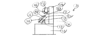
前記刃物2を研摩する刃物研摩装置8は、図2・図3に示す如く、ベッド10上にテーブル12とフレーム14とを設けている。
The blade polishing apparatus 8 for polishing the
前記テーブル12には、両端に立設した支柱16に回動軸18により固定台20を回動可能に軸支して設け、固定台20の角度を調整する角度調整機構22を設け、固定台20をテーブル12に対して固定する固定機構24を設けている。角度調整機構22は、調整ハンドル26を備えている。固定機構24は、固定ハンドル28を備えている。
The table 12 is provided with a
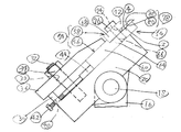
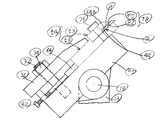
前記固定台20には、図1に示す如く、幅方向一側に支持部30を立設し、支持部30に隣接して固定具を構成する固定ボルト32を植設し、固定ボルト32に固定具を構成する固定ナット34を螺着して設けている。固定台20に固定ボルト32及び固定ナット34により固定される固定板36には、固定ボルト32を挿通する挿通孔38を形成して設けている。
As shown in FIG. 1, a support portion 30 is erected on one side in the width direction on the
また、固定台20には、支持部30に形成したねじ孔40に調整ボルト42を螺合している。調整ボルト42は、押し部材44を介して刃物2の固定位置を調整する。
Further, the
前記フレーム14には、刃物2に摺接されて研摩する砥石として、荒砥石46及び仕上げ砥石48を設けている。荒砥石46及び仕上げ砥石48は、夫々荒砥石用モータ50及び仕上げ砥石用モータ52により回転され、図示しない荒砥石用昇降機構及び仕上げ砥石用昇降機構により夫々刃物2に対して接離されるように昇降される。
The frame 14 is provided with a
刃物研磨装置8は、固定台20に刃物2を固定板36との間に挟んで固定ボルト32及び固定ナット34により固定し、調整ボルト42により押し部材44を介して刃物2を押進して固定位置を調整し、ベッド10上においてテーブル12とフレーム14とを相対的に移動させて、例えば、刃物2を固定したテーブル12に対して荒砥石46及び仕上げ砥石48を備えたフレーム14を移動させて、荒砥石46及び仕上げ砥石48により刃物2の刃先6を研摩する。
The blade polishing apparatus 8 sandwiches the
この刃物研磨装置8の刃物固定構造は、刃物2を固定台20に固定する固定用治具54を設けている。固定用治具54は、固定台20と固定板36との間に挟まれて固定ボルト32及び固定ナット34により固定される固定台側治具56と、この固定台側治具56に取り付けられて刃物2を固定台側治具56との間に挟んで固定する刃物側治具58とからなる。
The blade fixing structure of the blade polishing apparatus 8 includes a
前記固定台側治具56は、図6・図7に示す如く、刃物2の長手方向に長い長四角板形状に形成され、固定台20と固定板36とに挟持される挟持部60を設け、この挟持部60に段差部62を介して連続して刃物2及び刃物側治具58を支持する支持部64を設け、この支持部64にねじ孔66を形成して設けている。
As shown in FIGS. 6 and 7, the fixing
前記刃物側治具58は、図8・図9に示す如く、固定台側治具56の長手方向に沿うように四角板形状に形成され、固定台側治具56の支持部64に当接される当接部68を設け、この当接部68に段差部70を介して連続して刃物2を押圧する押圧部72を設け、当接部68に前記ねじ孔66に合致する挿通孔74を設けている。刃物側治具56は、固定台側治具56の支持部64に当接させて、挿通孔74に挿通した取付ボルト76を固定台側治具56のねじ孔66に螺着することにより、固定台側治具56に取り付けられる。
As shown in FIGS. 8 and 9, the cutter-
固定台側治具56及び刃物側治具58の少なくとも一方と刃物2との間には、固定用治具54に対する刃物2の固定位置を決定する位置決め機構78を設けている。
A
第1実施例の位置決め機構78は、図8・図9に示す如く、刃物側治具58の押圧部72の下面72aに長手方向に延びる係合突条80を設けるとともに、図4・図5に示す如く、刃物2の刃体4の上面4bに係合突条80と係合する係合溝条82を設けている。
As shown in FIGS. 8 and 9, the
次に作用を説明する。 Next, the operation will be described.
刃物研摩装置8は、固定台20に刃物2を固定する場合に、図1に示す如く、固定台側治具56の支持部64に刃物側治具58の当接部68を当接させ、刃物側治具58の挿通孔74に挿通した取付ボルト76を固定台側治具56のねじ孔66に螺着することにより、固定台側治具56に刃物側治具58を取り付けて固定用治具54を仮組する。
When the blade polishing apparatus 8 fixes the
仮組した固定用治具54は、固定ボルト32に螺着した固定ナット34をゆるめ、固定台20に固定台側治具56を当接させて、一端側を支持部30に当接させた固定板36の他端側との間に固定台側治具56の挟持部60を挟み、調整ボルト42により押し部材44を介して固定台側治具56を押進し、刃物2の刃先6の突出量が一定になるように調整して固定ナット34を締め付けることにより、固定台側治具56を固定台20に固定ボルト32及び固定ナット34により固定する。
The temporarily assembled
調整ボルト42により位置を調整されて固定台20に固定台側治具56を固定した固定用治具54は、取付ボルト76をゆるめて固定台側治具56と刃物側治具58との間をあけ、刃物側治具58の押圧部72の下面72aに設けた位置決め機構78の係合突条80に刃物2の刃体4の上面48bに設けた位置決め機構78の係合溝条82を係合させながら、固定台側治具56の支持部64と刃物側治具58の押圧部72との間に刃物2を挿入し、取付ボルト76を締め付ける。
The
これにより、刃物2は、固定台20に固定された固定用治具54の刃物側治具58と刃物2との間に設けた位置決め機構78によって、固定用治具54に対する刃物2の固定位置を決定され、固定用治具54に取り付けられる。
Thereby, the
刃物研摩装置8は、図2・図3に示す如く、刃物2を固定用治具54を介して固定した固定台20の角度、即ち刃物2の刃先4の角度を角度調整機構22の調整ハンドル26の操作により調整してから、固定台20をテーブル12に対して固定機構24の固定ハンドル28の操作により固定した後に、回転する荒砥石46及び仕上げ砥石48を順次に摺接させて研摩する。研摩の完了した刃物2は、取付ボルト76をゆるめて固定用治具54から外し、図示しない切削装置に取り付けることにより、木材等の被加工部材の切削に使用することができる。
As shown in FIGS. 2 and 3, the blade polishing apparatus 8 adjusts the angle of the fixing
このように、この刃物研摩装置8の刃物固定構造は、固定台側治具56と刃物側治具58とからなる固定用治具54を設け、この固定用治具54の刃物側治具58と刃物2との間に固定用治具54に対する刃物2の固定位置を決定する位置決め機構78を設けている。
As described above, the blade fixing structure of the blade polishing apparatus 8 includes the fixing
このため、この刃物研摩装置8の刃物固定構造は、位置決め機構78によって刃物2を固定台20に対して簡単な作業により正確に位置決めして固定することができ、刃物2を精度良く、また、効率良く研摩することができ、作業効率を向上することができる。
For this reason, the blade fixing structure of the blade polishing device 8 can accurately position and fix the
なお、この発明は、上述実施例に限定されることなく、種々応用改変が可能である。 The present invention is not limited to the above-described embodiments, and various application modifications can be made.
例えば、上述実施例においては、固定用治具54の刃物側治具58と刃物2との間に位置決め機構78を設けたが、固定用治具54の固定台側治具56と刃物2との間に位置決め機構78を設けることもできる。
For example, in the above-described embodiment, the
即ち、刃物研摩装置8の刃物固定構造は、図10に示す如く、位置決め機構78として、固定台側治具56の支持部64の上面64bに長手方向に延びる係合突条80を設けるとともに、刃物2の刃体4の下面4aに係合突条80と係合する係合溝条82を設けることにより、刃物2を固定台20に対して簡単な作業により正確に位置決めして固定することができ、刃物2を精度良く、また、効率良く研摩することができるものである。
That is, the blade fixing structure of the blade polishing apparatus 8 is provided with an engaging
この発明の刃物研摩装置の刃物固定構造は、固定用治具の固定台側治具及び刃物側治具の少なくとも一方と刃物との間には固定用治具に対する刃物の固定位置を決定する位置決め機構を設けたことにより、刃物を固定台に対して簡単な作業により正確に位置決めして固定することができ、刃物を精度良く、また、効率良く研摩することができるものであり、各種の産業機械の部品を固定に適用することができる。 The blade fixing structure of the blade polishing apparatus according to the present invention is a positioning for determining a fixing position of the blade with respect to the fixing jig between at least one of the fixing base side jig and the blade side jig of the fixing jig and the blade. By providing a mechanism, it is possible to accurately position and fix the blade with a simple work with respect to the fixed base, and to polish the blade with high accuracy and efficiency. Machine parts can be applied for fixing.
2 刃物
4 刃体
6 刃先
8 刃物研摩装置
10 ベッド
12 テーブル
14 フレーム
18 回動軸
20 固定台
22 角度調整機構
24 固定機構
30 支持部
32 固定ボルト
34 固定ナット
36 固定板
42 調整ボルト
44 押し部材
46 荒砥石
48 仕上げ砥石
54 固定用治具
56 固定台側治具
58 刃物側治具
76 取付ボルト
78 位置決め機構
80 係合突条
82 係合溝条
2
Claims (3)
Priority Applications (1)
| Application Number | Priority Date | Filing Date | Title |
|---|---|---|---|
| JP2004098574A JP2005279867A (en) | 2004-03-30 | 2004-03-30 | Cutter fixing structure of cutter polishing device |
Applications Claiming Priority (1)
| Application Number | Priority Date | Filing Date | Title |
|---|---|---|---|
| JP2004098574A JP2005279867A (en) | 2004-03-30 | 2004-03-30 | Cutter fixing structure of cutter polishing device |
Publications (2)
| Publication Number | Publication Date |
|---|---|
| JP2005279867A true JP2005279867A (en) | 2005-10-13 |
| JP2005279867A5 JP2005279867A5 (en) | 2007-05-17 |
Family
ID=35178788
Family Applications (1)
| Application Number | Title | Priority Date | Filing Date |
|---|---|---|---|
| JP2004098574A Pending JP2005279867A (en) | 2004-03-30 | 2004-03-30 | Cutter fixing structure of cutter polishing device |
Country Status (1)
| Country | Link |
|---|---|
| JP (1) | JP2005279867A (en) |
Cited By (2)
| Publication number | Priority date | Publication date | Assignee | Title |
|---|---|---|---|---|
| CN102357822A (en) * | 2011-10-20 | 2012-02-22 | 无锡海特精密模具有限公司 | Jig for processing automobile air conditioning die circular cutter |
| CN103692297A (en) * | 2013-12-13 | 2014-04-02 | 绵阳市绵工工具有限公司 | Device for processing blade circular arc |
-
2004
- 2004-03-30 JP JP2004098574A patent/JP2005279867A/en active Pending
Cited By (3)
| Publication number | Priority date | Publication date | Assignee | Title |
|---|---|---|---|---|
| CN102357822A (en) * | 2011-10-20 | 2012-02-22 | 无锡海特精密模具有限公司 | Jig for processing automobile air conditioning die circular cutter |
| CN102357822B (en) * | 2011-10-20 | 2015-02-25 | 无锡海特精密模具有限公司 | Jig for processing automobile air conditioning die circular cutter |
| CN103692297A (en) * | 2013-12-13 | 2014-04-02 | 绵阳市绵工工具有限公司 | Device for processing blade circular arc |
Similar Documents
| Publication | Publication Date | Title |
|---|---|---|
| US8197304B2 (en) | Method and apparatus for sharpening a tool blade | |
| CN1727140A (en) | Jig apparatus | |
| US6592307B2 (en) | Planing device for removing weld beads on car sheet metal | |
| US20060101971A1 (en) | Miter saw workpiece stop | |
| US7115027B2 (en) | Grinding tool for sharpening work pieces | |
| US7335093B1 (en) | Blade sharpening holder | |
| JP2008006525A (en) | Grinding machine of saw chain | |
| JP2005279867A (en) | Cutter fixing structure of cutter polishing device | |
| JP2005279867A5 (en) | ||
| US7666067B2 (en) | Method and device for sharpening a cutting tool | |
| KR200478673Y1 (en) | Knife supporting apparatus | |
| US4961287A (en) | Wood jointer and planer blade sharpening holder | |
| JP2011143485A (en) | Dressing and grinder device | |
| CN107639755B (en) | A kind of processing method of graphite vanes pump blade | |
| JP2007038356A (en) | Mounting structure of saw chain in polisher for chain saw | |
| CN211615880U (en) | Horizontal disc saw lifting adjusting mechanism for edge lifting device | |
| RU2036772C1 (en) | Device for manual sharpening of wood-working tool | |
| CN217749955U (en) | Single suction nozzle clamp | |
| JP2004141998A (en) | Workbench | |
| CN218397461U (en) | Rod material fine grinding and slotting processing integrated machine | |
| US6669541B2 (en) | Abrading method and holding device | |
| US20080301953A1 (en) | Cutting guide system and method | |
| JP2014046393A (en) | Rotary blade polishing device for bush cutter | |
| KR200395499Y1 (en) | Control apparatus of grinding angle for blade of a knife using woodworking tool | |
| JP2007210300A (en) | End chamfering device for ruled line forming tape |
Legal Events
| Date | Code | Title | Description |
|---|---|---|---|
| A521 | Written amendment |
Effective date: 20070323 Free format text: JAPANESE INTERMEDIATE CODE: A523 |
|
| A621 | Written request for application examination |
Free format text: JAPANESE INTERMEDIATE CODE: A621 Effective date: 20070323 |
|
| A977 | Report on retrieval |
Free format text: JAPANESE INTERMEDIATE CODE: A971007 Effective date: 20080919 |
|
| A131 | Notification of reasons for refusal |
Effective date: 20080926 Free format text: JAPANESE INTERMEDIATE CODE: A131 |
|
| A02 | Decision of refusal |
Free format text: JAPANESE INTERMEDIATE CODE: A02 Effective date: 20090217 |