JP2005277643A - Imaging device - Google Patents
Imaging device Download PDFInfo
- Publication number
- JP2005277643A JP2005277643A JP2004086302A JP2004086302A JP2005277643A JP 2005277643 A JP2005277643 A JP 2005277643A JP 2004086302 A JP2004086302 A JP 2004086302A JP 2004086302 A JP2004086302 A JP 2004086302A JP 2005277643 A JP2005277643 A JP 2005277643A
- Authority
- JP
- Japan
- Prior art keywords
- wavelength selection
- selection filter
- image
- optical path
- subject
- Prior art date
- Legal status (The legal status is an assumption and is not a legal conclusion. Google has not performed a legal analysis and makes no representation as to the accuracy of the status listed.)
- Pending
Links
Images


Abstract
Description
本発明は、二次元バーコード等の二値画像からなるデジタル情報の読み取りに好適な撮像装置に関する。 The present invention relates to an imaging apparatus suitable for reading digital information composed of binary images such as two-dimensional barcodes.
近年、撮像技術及び画像処理技術の進歩により、携帯の可能な小型の電子機器に撮像装置を内蔵させることが一般化している。例えば、カメラ付き携帯電話機は、撮像装置を内蔵した通信機器として現在広く普及しており、その通信機能を用いて撮影画像の送受信が簡単に行える。また、カメラ付き携帯電話機は、内蔵される撮像素子の高画素化が進み、従来よりも情報量の大きい画像を取り扱うことが可能となり、娯楽的な写真撮影を目的とする他に、書類等の文字を記録したり、二次元バーコードのように二値画像として符号化された情報を記録するという新たな用途が提案されている。 In recent years, with the advance of imaging technology and image processing technology, it has become common to incorporate an imaging device in a small portable electronic device. For example, a camera-equipped mobile phone is now widely used as a communication device with a built-in imaging device, and can easily transmit and receive a captured image using its communication function. In addition, camera-equipped mobile phones have built-in image sensors that have a higher pixel count and can handle images with a larger amount of information than conventional ones. A new application has been proposed in which characters are recorded or information encoded as a binary image such as a two-dimensional barcode is recorded.
しかしながら、携帯型の電子機器に内蔵される撮像装置は、そのコンパクト性を損なうことのないように、被写体光を結像させるレンズの構成が簡素にならざるを得ず、残存する収差は、カメラ用レンズ等に比べて大きくなる。特に、倍率色収差は、非球面レンズを利用しても補正することができず、上述した二次元バーコード等の符号化された画像情報や、色情報の不要な文字等を記録する場合には鮮鋭度や解像度の低下を招き、これらの情報を正確に読み取れなくなるという不都合が生じる。 However, an imaging device built in a portable electronic device has to have a simple lens configuration that forms an image of subject light so as not to impair its compactness. It becomes larger than a lens for use. In particular, lateral chromatic aberration cannot be corrected even by using an aspheric lens, and when recording encoded image information such as the above-described two-dimensional barcode, characters that do not require color information, or the like. This causes a disadvantage that sharpness and resolution are lowered, and these pieces of information cannot be read accurately.
本発明は、上記事情を考慮してなされたもので、カラー撮影が行えると同時に、符号化された画像情報や文字情報等の二値画像を正確に読み取れるようにした撮像装置を提供することを目的とする。 The present invention has been made in consideration of the above circumstances, and provides an image pickup apparatus that can perform color photographing and can accurately read binary images such as encoded image information and character information. Objective.
上記目的を達成するために、本発明は、画素を構成する受光素子上にオンチップカラーフィルタを有する撮像素子によりカラー撮影が可能な単板式の撮像装置であって、撮像素子に被写体光を結像させる光学系と、被写体光の特定の波長域の光を透過させる波長選択フィルタと、撮像素子に被写体光を入射させる撮影光路から退避する退避位置と光路中に進入する進入位置との間で波長選択フィルタを移動させ、撮像素子に入射する被写体光を例えば単色光と通常光とに切り替える切替え手段とを備えたことを特徴とする。 In order to achieve the above object, the present invention is a single-plate type imaging apparatus capable of performing color photography with an imaging element having an on-chip color filter on a light receiving element that constitutes a pixel, and connects subject light to the imaging element. An optical system to be imaged, a wavelength selection filter that transmits light in a specific wavelength range of subject light, and a retraction position that retreats from the photographing optical path that causes the subject light to enter the image sensor and an entry position that enters the optical path. The wavelength selection filter is moved, and switching means for switching subject light incident on the image sensor to, for example, monochromatic light or normal light is provided.
また、近距離の被写体に対してピントが合う第1の領域と、遠距離の被写体に対してピントが合う第2の領域との間で前記光学系の少なくとも一部をその光軸に沿って移動させるピント変更手段と、前記切替え手段により前記波長選択フィルタが前記進入位置に移動したときに前記光学系の少なくとも一部を前記第1の位置に移動させる連動手段とを備えたことを特徴とする。 In addition, at least a part of the optical system is arranged along the optical axis between the first region focused on a short-distance subject and the second region focused on a long-distance subject. And a focus changing means for moving, and an interlocking means for moving at least a part of the optical system to the first position when the wavelength selection filter is moved to the entry position by the switching means. To do.
本発明の撮像装置によれば、紙面上の文字や二次元バーコード等の符号化された二値画像等を記録する際に、光学系に入射する光又は撮像素子に入射する光を特定の波長域に制限しているから、解像度低下の原因となる色収差の影響を排除して文字や二値画像等を高精度に記録することができる。 According to the imaging apparatus of the present invention, when recording encoded binary images such as characters on a paper or a two-dimensional barcode, the light incident on the optical system or the light incident on the imaging element is specified. Since the wavelength range is limited, it is possible to record characters, binary images, and the like with high accuracy by eliminating the influence of chromatic aberration that causes a reduction in resolution.
また、波長選択フィルタを光軸上に移動させると同時に、近距離撮影に適したピント位置に光学系を動かしているから、近接撮影の選択によってモノクロ撮影が自動的に選択され、文字や二値画像等の記録時に別途ピント調節を行う手間が必要なく便利である。 In addition, the wavelength selection filter is moved on the optical axis and at the same time the optical system is moved to a focus position suitable for short-distance shooting, so monochrome shooting is automatically selected by selecting close-up shooting, and text and binary values are selected. This is convenient because there is no need to separately adjust the focus when recording an image or the like.
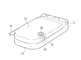
図1において、携帯電話機10は、ヒンジ部11を介して回動自在に連結された受話部12と送話部13とからなる。受話部12は、通話先の電話番号や画像等を表示する液晶表示装置14と、受話用スピーカー15とを前面に備え、背面にはアンテナ16が設けられている。送話部13には、電話番号や五十音、アルファベット等の入力が可能な操作部17と、送話用マイク18が設けられている。
In FIG. 1, a mobile phone 10 includes a
図2において、携帯電話機10は、受話用スピーカー15と送話用マイク18とを向かい合わせにして受話部12と送話部13とが折りたたまれることにより、不使用状態となる。この不使用状態では、液晶表示装置14と操作部17は内側に隠される。受話部12にはカメラ19が内蔵されており、受話部12の背面から撮影レンズ20が露呈されている。受話部12の側縁部分には、ピント切替えレバー21が設けられている。ピント切替えレバー21は、受話部12に内蔵されたカメラ19を使用して、例えば被写体が20cm〜50cmの至近距離にあるマクロ撮影と、被写体から1m以上の距離をおいた標準撮影とを切替えるときに操作される。
In FIG. 2, the cellular phone 10 is in a non-use state when the receiving
図3において、受話部12に内蔵されたカメラ19には、例えばCCDイメージセンサからなる撮像素子25が設けられている。撮像素子25は、画素となる受光素子がマトリクス状に配列されており、各受光素子上に入射光を色分解するカラーフィルタが設けられている。このカラーフィルタには、入射光を例えば赤(R)、緑(G)、青(B)に色分解するための3種類のフィルタがあり、各受光素子ではR,G,Bのいずれかの光が検出され、撮像素子25から色情報を含む画像信号が出力される。
In FIG. 3, the
撮像素子25は、固定枠26の後部に固定されている。固定枠26には、前レンズ枠27と、後レンズ枠28と、マクロリング29とが取付けられている。前レンズ枠27には、撮影レンズ20を構成する第1レンズ20a、第2レンズ20bが固定されている。後レンズ枠28には、第3レンズ20cが固定されている。第1レンズ20a〜第3レンズ20cは、入射した被写体光を撮像素子25の撮像面上で結像させる。マクロリング29は、固定枠26に対して所定角度の範囲で回動自在に設けられており、ピント切替えレバー21の操作力が伝達されることにより回動する。
The
レンズカバー30は、受話部12の外装体の開口部分に嵌め込まれた無色の透明板からなり、第1レンズ20a等に汚れやホコリ等が付着したり、傷がつくことを防ぐ。バネ31は、前レンズ枠27と固定枠26とを連結する。前レンズ枠27は、固定枠26の内部で撮影レンズ20の光軸A1に沿って移動自在に設けられ、バネ31は前レンズ枠27を撮像素子25が設けられた後方側(像面側)に向けて付勢する。
The
レンズカバー30と第1レンズ20aの間には、波長選択フィルタ32が保持されたフィルタ保持枠33が設けられている。波長選択フィルタ32は、撮像素子25の画素に設けられたGのカラーフィルタと同じ光透過特性を有しており、レンズカバー30からの入射光のうち、その波長が約500nm〜600nmの緑光のみを選択的に透過させる。フィルタ保持枠33は、ピント切替えレバー21を介してマクロリング29が操作されることにより変位する。このとき、フィルタ保持枠33は、固定枠26に嵌合した軸33aを中心に回動し、レンズカバー30と第1レンズ20aの間の撮影光路内に進入する位置と、両者の間から抜け出して撮影光路の外に退避する位置との間で移動する。波長選択フィルタ32が、レンズカバー30と第1レンズ20aの間に位置する時は、レンズカバー30から入射した被写体光は上記波長域以外の光がカットされ、緑の被写体光のみが撮影レンズ20を透過して撮像面上で結像する。
A
図4において、前レンズ枠27には、マクロリング29と対面する背面に、三角柱形状の3つの突起35が同一円周上に120度ごとに設けられている。また、マクロリング29には、同様にして120度ごとに四角柱形状の3つの突起36が設けられている。ピント切替えレバー21の操作によりマクロリング29が回動したとき、突起36は、前レンズ枠27の後面を摺接して突起35の上をそれぞれ移動する。突起36が突起35の斜面の上を移動すると、固定枠26に対して前レンズ枠27が光軸方向に移動する。すなわち、第1レンズ20aと第2レンズ20cとが撮像素子25から離れる前方側(被写体側)と撮像素子25に近づく後方側(像面側)へと移動する。前レンズ枠27が前方側へ移動すると、至近距離の撮影時に撮像素子25の撮像面にピントを合わせることができマクロ撮影が可能となる。なお、突起36が突起35の斜面の低い位置に向かって移動するときには、2つのバネ掛け部37に取付けられるバネ31の弾性力により前レンズ枠27が後方側へ移動する。
In FIG. 4, the
図5において、マクロリング29には、ピント切替えレバー21の操作力が伝達される伝達部40と、マクロリング29が回動したときにフィルタ保持枠33の被押圧部41を押圧する押圧部42とが設けられている。押圧部42は、マクロリング42の略半径方向に突出した部分からマクロリング29の回転方向に沿って延びた略L字形状を有する。フィルタ保持枠33は、マクロリング29が回動して押圧部41が被押圧部40を押圧したときに軸33aを中心に回動し、波長選択フィルタ32を撮影光路から退避する位置に変位させる。被押圧部41の作用点から軸33aまでの距離は、押圧部38の作用点からマクロリング29の回動中心までの距離より短く、マクロリング29の回動する角度に対してフィルタ保持枠33の回動する角度は大きくなる。押圧部42は、被押圧部41との接触位置の変化に対応できるように、その先端隅の部分を切欠いた形状をしている。バネ43は、被押圧部41と押圧部42の間に設けられている。押圧部42が被押圧部41から離れる方向にマクロリング29が回転したとき、バネ43は伸長してその弾性力により被押圧部41を引っ張ってフィルタ保持枠33を回動させ、撮影光路から退避した位置にある波長選択フィルタ32を撮影光路に進入する位置に変位させる。
In FIG. 5, the
図6において、マイクロコンピュータからなるシステムコントローラ45は、通話機能、撮影機能を制御するプログラムに基いて携帯電話機10の各部の動作を電気的に管理し、操作部17の入力操作に従って電話モードとカメラモードの切替え等を行う。画像信号処理回路46は、カメラモードの作動時に撮像素子から出力される画像信号に対し、増幅処理、ノイズ処理、カラー調節処理等を行うとともに、デジタル変換処理を行う。内蔵メモリ47は、撮影された画像データ、電話番号や通話履歴等の情報を記憶する。通信インターフェース48は、アンテナ16から受信した電波の復調、送信する信号の変調を行う。音声処理回路49は、受話用スピーカー15と送話用マイク18に入出力される音声信号の処理を行う。
In FIG. 6, a
バーコード解析部50は、内蔵メモリ47に記憶された画像データが二次元バーコードである場合に、バーコードを解析して符号化された情報を取り出し、これをテキストデータとして内蔵メモリ47に記憶する。センサ51は、ピント切替えレバー21の操作位置を検出し、システムコントローラ45にピント切替えレバー21の状態を入力する。ピント切替えレバー21がマクロ撮影を示す位置にあるとき、システムコントローラ45は、撮像素子25から出力されるカラー情報をもった画像信号をグレースケールの画像信号に変換する命令を画像信号処理回路46に送る。
When the image data stored in the built-in
次に、携帯電話機10の作用について説明する。操作部17に設けられたキーを適宜入力操作することにより、携帯電話機10を電話モードとカメラモードとに切替えることができる。携帯電話機10をカメラモードに設定し、風景や人物等を撮影するときには、ピント切替えレバー21を通常撮影用の位置に操作する。このとき、カメラ19では、ピント切替えレバー21の操作に対応してマクロリング29が回動し、フィルタ保持枠33の被押圧部41がマクロリング29の押圧部42に押圧される。フィルタ保持枠33はレンズカバー30と第1レンズ20aの間から波長選択フィルタ32を退避させ、撮影光路の外に移動させる。
Next, the operation of the mobile phone 10 will be described. The mobile phone 10 can be switched between the telephone mode and the camera mode by appropriately inputting keys provided on the
システムコントローラ45は、撮像素子25を駆動させる。撮影レンズ20には被写体光が入射し、撮像素子25の撮像面上で被写体光が結像する。撮像素子25は撮像面上に形成された被写体像を光電変換し、カラー情報をもった画像信号を画像信号処理回路46に送る。画像信号処理回路46では、画像信号に対して各種の信号処理が行われる。システムコントローラ45は画像信号を液晶表示装置14に送り、液晶表示装置14に被写体の画像が表示される。操作部17に設けられたシャッタキーを操作すると、システムコントローラ45に入力された画像信号が取り込まれて圧縮処理等が行われ、内蔵メモリ47に画像データとして記憶される。
The
一方、至近距離で撮影を行う際には、ピント切替えレバー21をマクロ撮影用の位置に操作する。ピント切替えレバー21の操作によって、押圧部42が被押圧部41から離れる方向にマクロリング29が回動する。バネ43は伸長し、その弾性力でフィルタ保持枠33を回動させる。これにより、波長選択フィルタ32が、レンズカバー30と第1レンズ20aとの間に差し込まれる。また、マクロリング29の回動により、マクロリング29の突起36が前レンズ枠27の突起35の上に移動し、前レンズ枠27が光軸A1に沿って前方側へ移動するので、被写体が至近距離にある場合でも撮像面上で像のピントが合うようになる。
On the other hand, when shooting at a close distance, the
波長選択フィルタ32により、撮影レンズ20に入射する被写体光は緑色光のみに制限され、撮像素子25では緑色の被写体像が撮像される。システムコントローラ45は、センサ51からの入力信号を受けて画像信号処理回路46に命令信号を送り、画像信号処理回路46は撮像素子25によって撮像された画像をグレースケール画像に変換する処理を行う。撮影操作がなされると、内蔵メモリ47にはグレースケール形式に変換された画像データが記憶される。バーコード解析部50では、内蔵メモリ47に記憶された画像データを二値化して二次元バーコードを撮影した画像であるか否かが識別される。二次元バーコードが検出されると、その解析処理が行われ、符号化された情報をテキストデータに変換し、これを内蔵メモリ47に記憶させる。
The object light incident on the taking lens 20 is limited to only green light by the
以上のようにして、被写体を至近距離で撮影する際には、撮像面上に被写体像のピントを合わせるための撮影レンズ20の移動と同時に、波長選択フィルタ32によって入射光が単色光に制限され、撮影された白黒画像から二次元バーコードを識別する処理と、その解析が自動的に行われる。また、被写体と距離をおいた撮影をする際には、撮像面にピントの合う位置に撮影レンズ20が移動すると同時に、波長選択フィルタ32が撮影光路上から退避してカラー撮影を行うことができる。
As described above, when the subject is photographed at a close distance, the incident light is limited to monochromatic light by the
なお、上記実施形態では、撮影レンズ20を光軸方向に移動させるための操作と、波長選択フィルタ32を撮影光路に対して出し入れするための操作を共通化しているが、これらの操作は別々に行えるようにしてもよい。波長選択フィルタ32は、撮影レンズ20の最も物体側に配置されることに限られず、複数のレンズの間に配置してもよい。結像光学系としてズームレンズを備えた撮像装置では、ズーミングに連動して波長選択フィルタ32を撮影光路上に出し入れできるようにしてもよい。
In the above embodiment, the operation for moving the photographic lens 20 in the optical axis direction and the operation for moving the
本発明は、携帯電話機の他、PDA等の情報端末機器、携帯可能な小型の電子機器に内蔵させて用いることができる。 The present invention can be used by being incorporated in an information terminal device such as a PDA or a portable small electronic device in addition to a mobile phone.
10 携帯電話機
19 カメラ
20 撮影レンズ
21 ピント切替えレバー
25 撮像素子
27 前レンズ枠
28 後レンズ枠
29 マクロリング
32 波長選択フィルタ
33 フィルタ保持枠
DESCRIPTION OF SYMBOLS 10
Claims (2)
Priority Applications (1)
| Application Number | Priority Date | Filing Date | Title |
|---|---|---|---|
| JP2004086302A JP2005277643A (en) | 2004-03-24 | 2004-03-24 | Imaging device |
Applications Claiming Priority (1)
| Application Number | Priority Date | Filing Date | Title |
|---|---|---|---|
| JP2004086302A JP2005277643A (en) | 2004-03-24 | 2004-03-24 | Imaging device |
Publications (1)
| Publication Number | Publication Date |
|---|---|
| JP2005277643A true JP2005277643A (en) | 2005-10-06 |
Family
ID=35176856
Family Applications (1)
| Application Number | Title | Priority Date | Filing Date |
|---|---|---|---|
| JP2004086302A Pending JP2005277643A (en) | 2004-03-24 | 2004-03-24 | Imaging device |
Country Status (1)
| Country | Link |
|---|---|
| JP (1) | JP2005277643A (en) |
Cited By (7)
| Publication number | Priority date | Publication date | Assignee | Title |
|---|---|---|---|---|
| JP2006242994A (en) * | 2005-02-28 | 2006-09-14 | Nidec Sankyo Corp | Lens driving unit |
| KR100755596B1 (en) * | 2005-11-30 | 2007-09-06 | 후지쯔 가부시끼가이샤 | Electronic apparatus having camera |
| JP2007286084A (en) * | 2006-04-12 | 2007-11-01 | Nec Corp | Camera-integrated portable terminal apparatus |
| WO2008037094A1 (en) * | 2006-09-29 | 2008-04-03 | Abb Research Ltd | Automatic device registration system with barcode identification and maintenance information generation |
| CN100437329C (en) * | 2006-09-18 | 2008-11-26 | 浙江大学 | Micro-ultrasonic motor mobile phone quickcam image focusing structure |
| WO2017049922A1 (en) * | 2015-06-17 | 2017-03-30 | 广州市巽腾信息科技有限公司 | Image information collection apparatus, image collection method, and application thereof |
| CN111147771A (en) * | 2019-12-30 | 2020-05-12 | 安徽惠洲地质安全研究院股份有限公司 | Mining imaging device, equipment and method |
-
2004
- 2004-03-24 JP JP2004086302A patent/JP2005277643A/en active Pending
Cited By (10)
| Publication number | Priority date | Publication date | Assignee | Title |
|---|---|---|---|---|
| JP2006242994A (en) * | 2005-02-28 | 2006-09-14 | Nidec Sankyo Corp | Lens driving unit |
| KR100755596B1 (en) * | 2005-11-30 | 2007-09-06 | 후지쯔 가부시끼가이샤 | Electronic apparatus having camera |
| US7557856B2 (en) | 2005-11-30 | 2009-07-07 | Fujitsu Limited | Electronic apparatus having shooting device and manual focus switch ring that is engaged with shooting device holder in housing |
| JP2007286084A (en) * | 2006-04-12 | 2007-11-01 | Nec Corp | Camera-integrated portable terminal apparatus |
| CN100437329C (en) * | 2006-09-18 | 2008-11-26 | 浙江大学 | Micro-ultrasonic motor mobile phone quickcam image focusing structure |
| WO2008037094A1 (en) * | 2006-09-29 | 2008-04-03 | Abb Research Ltd | Automatic device registration system with barcode identification and maintenance information generation |
| US9477976B2 (en) | 2006-09-29 | 2016-10-25 | Abb Research Ltd. | Automatic device registration system with barcode identification and maintenance information generation |
| WO2017049922A1 (en) * | 2015-06-17 | 2017-03-30 | 广州市巽腾信息科技有限公司 | Image information collection apparatus, image collection method, and application thereof |
| CN111147771A (en) * | 2019-12-30 | 2020-05-12 | 安徽惠洲地质安全研究院股份有限公司 | Mining imaging device, equipment and method |
| CN111147771B (en) * | 2019-12-30 | 2022-05-03 | 安徽惠洲地质安全研究院股份有限公司 | Mining imaging device, equipment and method |
Similar Documents
| Publication | Publication Date | Title |
|---|---|---|
| US8226006B2 (en) | Code reader device which displays a code extracting area of a subject image to have a size based on a specified display size of the subject image, and recording medium therefor | |
| CN101480040B (en) | Active autofocus window | |
| JP4292795B2 (en) | Mobile device with camera | |
| US20150237273A1 (en) | Image capture device, anomalous oblique incident light detection method, and recording medium | |
| JP5946970B2 (en) | Imaging apparatus and imaging method | |
| JP5866478B2 (en) | Imaging apparatus, signal processing method, and signal processing program | |
| CN1837939B (en) | Mobile communication terminal having camera function and method for performing the same | |
| WO2004064382B1 (en) | Optical code reading device having more than one imaging engine | |
| CN104159021A (en) | Imaging apparatus, imaging method and program | |
| JP4160920B2 (en) | Camera system and camera body | |
| JP2005249824A (en) | Imaging apparatus | |
| CN101373253A (en) | Imaging device, and control method for imaging device | |
| CN104737528A (en) | Imaging device and image display method | |
| EP1938585B1 (en) | Optical recording apparatus for wireless equipment | |
| JP2002027047A (en) | Portable information terminal equipment | |
| JP4210189B2 (en) | Imaging device | |
| JP2007147951A (en) | Wavefront coding image forming apparatus and imaging apparatus | |
| JP2005277643A (en) | Imaging device | |
| KR20060014228A (en) | Multi focus photographing method and apparatus in a mobile communication terminal having many cameras | |
| JP2003069868A (en) | Personal digital assistant with camera function | |
| JP2006166373A (en) | Communication information terminal | |
| JP2003110895A (en) | Personal digital assistance device with camera function | |
| JP2003069869A (en) | Personal digital assistant with camera function | |
| KR100399107B1 (en) | Wireless cellular phone for having digital camera function | |
| KR100819812B1 (en) | Digital image processing apparatus comprising radio frequency identification system, and method of controlling the same |
Legal Events
| Date | Code | Title | Description |
|---|---|---|---|
| A621 | Written request for application examination |
Free format text: JAPANESE INTERMEDIATE CODE: A621 Effective date: 20061023 |
|
| A131 | Notification of reasons for refusal |
Free format text: JAPANESE INTERMEDIATE CODE: A131 Effective date: 20081224 |
|
| A02 | Decision of refusal |
Free format text: JAPANESE INTERMEDIATE CODE: A02 Effective date: 20090415 |