JP2005271925A - Disk fixing device - Google Patents
Disk fixing device Download PDFInfo
- Publication number
- JP2005271925A JP2005271925A JP2004083795A JP2004083795A JP2005271925A JP 2005271925 A JP2005271925 A JP 2005271925A JP 2004083795 A JP2004083795 A JP 2004083795A JP 2004083795 A JP2004083795 A JP 2004083795A JP 2005271925 A JP2005271925 A JP 2005271925A
- Authority
- JP
- Japan
- Prior art keywords
- disk
- elastic locking
- center
- annular rib
- locking piece
- Prior art date
- Legal status (The legal status is an assumption and is not a legal conclusion. Google has not performed a legal analysis and makes no representation as to the accuracy of the status listed.)
- Pending
Links
Images


Abstract
Description
本発明は、CD又はDVD等のディスクに形成された中心孔を収納ケース内に固定するためのディスク固定装置に関する。 The present invention relates to a disk fixing device for fixing a central hole formed in a disk such as a CD or a DVD in a storage case.
CD又はDVD等のディスクを保管する場合、一般的には、購入時の収納ケースに入れた状態で保管する。この収納ケースは、図9に示すように、不図示のプラスティックケースの内側に収納するトレー31の中央にボス32が形成されてなるものである。円形のボス32はトレー31の中央面上から多数のツメ33、33…が互いに隙間を有して突出され、それぞれのツメ33は上端が中央方向に折曲されると共に、中央部が空隙34を有することによって、それぞれのツメ33、33…が弾性変形可能とされている。
When storing a disk such as a CD or a DVD, the disk is generally stored in a storage case at the time of purchase. As shown in FIG. 9, this storage case is formed by forming a
このようなボス32の外径はディスクの中心孔よりもわずかに大径を有する。従って、ボス32にディスクの中心孔を押し下げると、ボス32の夫々のツメ33、33…が内方に僅かに屈曲してディスクの中心孔を係止した状態にする。
The outer diameter of the
しかしながら、このような係止状態では、収納ケースに外圧がかかって変形した場合、ディスクの中心孔がボス32の外周から容易に外れるという問題があった。
However, in such a locked state, there has been a problem that the center hole of the disk is easily detached from the outer periphery of the
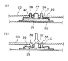
この問題を解消するために、例えば、特許文献1に掲げる装置が提案されている。この装置は、図10(a)に示すように、CDの中央に形成されたホールCを保持するためのホールホルダに関するものである。
In order to solve this problem, for example, an apparatus listed in
その構成は、プラスティック製のプレート35の上面中央に円形の上板36が形成され、この上板36の中央には円形の中央突部37が形成されると共に、その周囲には複数の周辺突部38が形成され、各周辺突部38の外周上端は肉厚部40が形成されてなるものである。
The structure is such that a circular
なお、上板36と中央突部37及び複数の周辺突部38の形成部との間にはウレタン材によるスプリング39が充填され、中央突部37及び複数の周辺突部38の弾性を確保するようにしている。
A
このような構成のホールホルダにCDのホールCを挿着するには、図10(a)に示すように、CDのホールCを周辺突部38の外周に嵌め込んで押し下げると、CDのホールCが各厚肉部40に係止された状態となる。
In order to insert the hole C of the CD into the hole holder having such a configuration, as shown in FIG. 10A, the hole C of the CD is pushed by fitting the hole C of the CD into the outer periphery of the
また、このように嵌め込まれたCDを取り出すには、図10(b)に示すように、中央突部37を指先で押し下げると、上板36が下方に撓んで中央突部37及び複数の周辺突部38、38…の外周が中央方向へ縮小するように変形し、その結果、CDのホールCが周辺突部38、38…の全周から外れた状態となる。
上記の構成においては、いずれもCDのホール(中心孔)をボス又は複数の周辺突部の外周に嵌め込んで係止状態にするものであり、いずれの構成においても、ボス又は周辺突部による係止構造は撓み性を有し、その係止構造を指先で押し下げることによって、ディスクを取り外すようにしている。 In any of the above-described configurations, the hole (center hole) of the CD is fitted into the outer periphery of the boss or the plurality of peripheral protrusions to be in a locked state. In any configuration, the boss or the peripheral protrusion is used. The locking structure is flexible, and the disk is removed by pushing down the locking structure with a fingertip.
ところが、このように撓み性を有することによってディスクを取り外す構造においては、盗難防止上の問題がある。即ち、販売店等においては、ディスクケースの内部にディスクを上記のように係止した状態で収納し、そのディスクケースの外方を透明ビニル等で包装した状態に展示している。このような収納状態に対して、新手の盗難としては、ディスクケースの蓋面の外側からほぼ中央を押すことにより、蓋を介して内部の係止構造を押圧することによりディスクを外した状態にしておき、ディスクケースの蓋の隙間にカッターを当てて透明ビニルの口を開き、その隙間から内部で外れたディスクを抜き出すというものである。 However, the structure in which the disk is removed by having such flexibility has a problem in preventing theft. That is, in a store or the like, a disc is stored inside the disc case in a locked state as described above, and the outside of the disc case is displayed in a state of being wrapped with transparent vinyl or the like. In such a stowed state, as a new type of theft, the disc is removed by pushing the inner locking structure through the lid by pushing the center from the outside of the lid surface of the disc case. In addition, a cutter is applied to the gap between the lids of the disc case to open the opening of the transparent vinyl, and the disc that has come off inside is extracted from the gap.
このように、ディスクの係止構造を押圧することによってディスクが離脱するタイプのものは、上記の手段によって盗難の対象にされてしまうおそれがあるため、これに対処するには、押圧することでディスクが外れない構造とする必要がある。 As described above, the type in which the disc is detached by pressing the disc locking structure may be the subject of theft by the above means. The disk must be structured so that it cannot be removed.
また、上記の従来構造において、図9に示すものは、ケース本体とトレーとの組み合わせからなり、図10(a)及び(b)に示すものは、ケース本体と上板と中央突部及び複数の周辺突部の形成部材とウレタン材によるスプリングとが別体であって、それぞれの部材を成形する工程と、接合する工程とを有し、製作の手間及びコスト高になるという問題があった。 Further, in the above conventional structure, the structure shown in FIG. 9 is a combination of a case body and a tray, and the structures shown in FIGS. The peripheral protrusion forming member and the spring made of urethane material are separate bodies, and each has a step of molding and joining each member, resulting in a problem of labor and cost of production. .
本発明はこのような問題点を解消するために成されたもので、保持部を押圧するだけではディスクが外れない係止構造とし、しかもディスクの係止状態を確実に保持すると共に、取り出す必要があるときは容易に取り外すことができ、しかも簡単な構造であって低コストで製造し得るディスク固定装置を提供することを目的とする。 The present invention has been made to solve such problems, and has a locking structure in which the disk cannot be removed simply by pressing the holding part, and the disk is securely held and taken out. It is an object of the present invention to provide a disk fixing device that can be easily removed when there is, and that can be manufactured at a low cost with a simple structure.
上記の目的を達成するために、本発明の請求項1は、ディスクの収納ケースの内側面上に所定の高さを有する環状リブが設けられ、該環状リブの内部に形成された中心穴の周縁に間隔をあけて面上に起立してなる複数の弾性係止片が前記環状リブの近傍に至る切込みで離間されたことによって夫々の弾性係止片が前記環状リブの近傍に至る弾性支持片を有することにより、夫々の弾性係止片が前記環状リブの近傍から独立的に弾性変形可能に形成され、これらの弾性係止片が全体としてディスクの中心孔に挿着される円形状の保持部を形成し、夫々の弾性係止片の上端が中央に向けて折曲された折曲部を有すると共に、夫々の折曲部の中心側先端が互いに所定間隔の隙間をあけて接近する一方、夫々の弾性係止片の外側の途中にツメが突設されてなり、ディスクの中心孔を前記保持部の外周に押しこむ際に、ディスクの中心孔の内周縁が夫々の弾性係止片を変形しながら夫々のツメを乗り越して係止状態となり、且つ前記保持部の中心を押圧した際に夫々の折曲部の中心側先端同士が互いに当接することによって夫々の弾性係止片の変形を規制することにより、前記夫々のツメに係止されたディスクが外れないようにしたことを特徴とする。
In order to achieve the above object, according to
また、本発明の請求項2は、請求項1において、前記弾性係止片は3個から構成されると共に、夫々の弾性係止片の折曲部の中心側先端が中心角を略三等分する角で形成された斜辺を有することを特徴とする。 Further, according to a second aspect of the present invention, in the first aspect, the elastic locking piece is composed of three pieces, and the center side tip of the bent portion of each elastic locking piece has a central angle approximately equal to the third angle. It has a hypotenuse formed by a corner to be divided.
さらに、本発明の請求項3は、請求項1又は2において、前記収納ケースの内側面上であって前記保持部から所定距離だけ離間した周部に前記保持部に挿着したディスクの外周を支持する環状リムが形成されると共に、該環状リムの少なくとも1箇所に前記ディスクの外周下部に指先を当てる部位として空所を有することを特徴とする。 Further, according to a third aspect of the present invention, in the first or second aspect, the outer periphery of the disk inserted into the holding portion is arranged on the inner surface of the storage case and spaced apart from the holding portion by a predetermined distance. An annular rim to be supported is formed, and at least one portion of the annular rim has a space as a portion where a fingertip is applied to the lower outer periphery of the disk.
以上のように構成された発明により、夫々の弾性係止片は、環状リブの近傍に至る切込みで離間されたことによって夫々の弾性係止片が環状リブの近傍に至る弾性支持片を有することにより、夫々の弾性係止片が環状リブの近傍から独立的に弾性変形可能に形成されているため、夫々の弾性係止片の撓み性が向上し、各弾性係止片が変形する際の折損を防止する構造とすることができる。 According to the invention configured as described above, each elastic locking piece has an elastic support piece that reaches the vicinity of the annular rib by being separated by a notch reaching the vicinity of the annular rib. Accordingly, each elastic locking piece is formed so as to be elastically deformable independently from the vicinity of the annular rib. Therefore, the flexibility of each elastic locking piece is improved, and each elastic locking piece is deformed. It can be set as the structure which prevents breakage.
また、保持部の外周にディスクの中心孔を挿着する際、ディスクの中心孔の内周縁が夫々の弾性係止片を変形しながら夫々のツメを乗り越して係止状態とされるため、挿着されたディスクは夫々のツメで係止されて、離脱し難いものとなる。 Also, when the disc center hole is inserted into the outer periphery of the holding portion, the inner peripheral edge of the disc center hole gets over the respective claws while being deformed by the respective elastic locking pieces, so that it is locked. The attached disc is locked by the respective claws and is difficult to be detached.
さらに、夫々の弾性係止片の折曲部における中心側先端が互いに所定間隔の隙間をあけて接近する構成とされているため、保持部の中心を指先で押圧した際に、夫々の折曲部の中心側先端同士が互いに当接することによって夫々の弾性係止片の変形を規制することにより、夫々のツメに係止されたディスクが外れない構造とすることができる。 Further, since the center-side ends of the bent portions of the respective elastic locking pieces are close to each other with a predetermined gap therebetween, when the center of the holding portion is pressed with the fingertip, By restricting the deformation of the respective elastic locking pieces by the tips on the center side of the parts coming into contact with each other, it is possible to make a structure in which the disk locked to each claw cannot be removed.
さらにまた、上記のように、夫々の弾性係止片の変形を規制することによって、夫々の弾性係止片が必要以上に変形しない構造として、各弾性係止片の折損を防止することが可能となる。 Furthermore, as described above, by restricting the deformation of each elastic locking piece, it is possible to prevent each elastic locking piece from being broken as a structure in which each elastic locking piece does not deform more than necessary. It becomes.
以下、本発明の実施例について図面を参照しながら説明する。 Embodiments of the present invention will be described below with reference to the drawings.
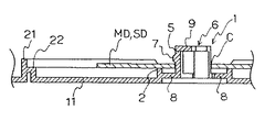
本実施例におけるCD又はDVD等のディスクDの収納ケース10は、図1に示すように、矩形を成す底板11と蓋板12とが長辺側の一辺に背板枠13を有して開閉自在に形成されると共に、底板11と蓋板12の夫々の三辺に外周枠14が形成され、底板11と蓋板12とを閉じることによって、開閉可能な矩形の薄型箱形状を成す収納ケース10が構成されている。
As shown in FIG. 1, a
なお、蓋板12の内側端部には2個の挟持片15、15が形成され、これらの挟持片15、15に説明書等を挟み込むことができる。
In addition, two
上記のように構成された収納ケース10の底板11側の内側面上には、図4に示すように、所定の高さを有する環状リブ2が形成されている。この環状リブ2は、例えば、2〜3mmの高さを有する環状の突起形状であって、直径約25mmを有するものであり、後述する保持部の外周にディスクDの中心孔Cを挿着したとき、ディスクDの片面が底板11の面から離間した状態で支持するようにしている(図7(c)参照)。
An
また、図4に示すように、環状リブ2の内部の中心には中心穴3が形成され、該中心穴3の周縁に間隔をあけて面上に起立してなる複数の弾性係止片5、5…が形成され、これらの複数の弾性係止片5、5…により全体として円形状の保持部6が形成されることにより、図3に示すように、保持部6の外周にディスクDの中心孔Cを挿着することができる。
As shown in FIG. 4, a
また、図2に示すように、夫々の弾性係止片5、5…は、その周部が、環状リブ2の近傍に至る切込み4で離間され、夫々の弾性係止片5、5…は環状リブ2の近傍に至る弾性支持片8を有することにより、夫々の弾性係止片5、5…が環状リブ2の近傍から独立的に弾性変形することが可能である。
As shown in FIG. 2, the respective
即ち、各弾性係止片5が変形する際は、夫々の弾性支持片8と一体的に撓むこととなって、夫々の弾性係止片5、5…の撓み性が向上するため、各弾性係止片5は、その起立部位からではなく、弾性支持片8と共に環状リブ2の近傍から撓むこととなり、各弾性係止片5、5…の変形の柔軟性を向上することができ、各弾性係止片5を折損し難い構造とすることが可能となる。
That is, when each
さらに、図4に示すように、夫々の弾性係止片5、5…の上端が中央に向けて折曲された折曲部9を有すると共に、夫々の折曲部9、9…の中心側先端が互いに所定間隔Gの隙間20をあけて接近する構成とされている。
Further, as shown in FIG. 4, the upper ends of the respective
本実施例において、弾性係止片5、5…は3個から構成され、夫々の弾性係止片5、5…の折曲部9、9…の中心側先端が中心角を略三等分する角で形成された斜辺9a、9aを有する構成とされている。
In this embodiment, the
また、図2又は図4に示すように、夫々の弾性係止片5、5…の外側の途中にツメ7、7…が突設され、ディスクDの中心孔Cを保持部6の外周に押しこむ際に、ディスクDの中心孔Cの内周縁が夫々の弾性係止片5、5…を変形しながら夫々のツメ7、7…を乗り越して係止状態にされる。
As shown in FIG. 2 or 4,
このような構成において、夫々の弾性係止片5、5…の折曲部9、9…における中心側先端が互いに所定間隔G(図4参照)の隙間20をあけて接近する構成とされているのは、次の理由による。即ち、図5(この図は、保持部6の通常の状態を逆にした状態で図示してある)に示すように、保持部6の中心を指先等で押圧した際に、夫々の折曲部9、9…の中心側先端同士が互いに当接することによって夫々の弾性係止片5、5…の変形を規制することによって、夫々のツメ7、7…に係止されたディスクDが外れないようにするためである。そのための所定間隔G(図4参照)としては、約1mm程度の隙間20とするのが好ましい。
In such a configuration, the center-side tips of the
また、このように夫々の弾性係止片5、5…の変形を規制することによって、夫々の弾性係止片5、5…が必要以上に変形しないようにして、各弾性係止片5、5…の折損を防止することができる。
In addition, by restricting the deformation of the respective
さらに、本実施例においては、図2又は図3に示すように、収納ケース10の内側面上であって保持部6から所定距離だけ離間した周部に保持部6に挿着したディスクDの外周を支持する環状リム21が形成された構成とされている。
Further, in the present embodiment, as shown in FIG. 2 or FIG. 3, the disk D inserted into the holding
この環状リム21は、図7(a)〜(c)に示すように、内側に低い段部22を有する形状とされ、この段部22に保持部6に挿着したディスクDの外周を支持することができる。この環状リム21は、直径120mmのCD又はDVDを収納し得る寸法とするのが望ましい。
As shown in FIGS. 7A to 7C, the
なお、図6に示すように、上記のコンパクトディスクDよりも小径のミニディスクMDまたはシングルディスクSDを収納すると、ディスクDの外周は環状リム21の段部22に到達せず、その外周下面を支持することができないが、上記のディスクDと同様に、ミニディスクMDまたはシングルディスクSDの中心孔Cを保持部6の外周に挿着することにより、環状リブ2の上端に支持され、夫々の弾性係止片5、5…のツメ7、7…で係止された固定状態を保つことができる。
As shown in FIG. 6, when a mini-disc MD or single disc SD having a smaller diameter than the compact disc D is accommodated, the outer periphery of the disc D does not reach the
また、図1乃至図3に示すように、上記の環状リム21の少なくとも1箇所にディスクDの外周下部に指先を当てる部位として空所23を形成することによって、図8(b)に示すように、保持部6に挿着したディスクDの取り出しを行う際、この空所23からディスクDの外周に指を当てて引き上げることにより、ディスクDの取り出しを容易に行うことができる。なお、図1乃至図3に示す環状リム21には空所23が対向位置に2個形成されているが、そのうちの1個でもよい。
Further, as shown in FIG. 1 to FIG. 3, by forming a void 23 as a part where the fingertip is applied to the lower part of the outer periphery of the disk D in at least one place of the
上記のように構成されたディスク固定装置1に、ディスクDを装置するには、図7(a)に示すように、ディスクDの中心孔Cを載置する。このとき、ディスクDの中心孔Cは夫々の弾性係止片5、5…のツメ7、7…上に係合された状態になる。
In order to place the disk D on the
次いで、図7(b)に示すように、このディスクDの中心孔Cの近傍の上面を指で下方に押し込むと、ディスクDの中心孔Cの内周縁が夫々の弾性係止片5、5…を中心方向に変形しながら夫々のツメ7、7…を乗り越して係止状態となる。このとき、図7(c)に示すように、ディスクDの中心孔Cは、環状リブ2の上端に支持されると共に、ツメ7、7…の下方に係止された状態となる。
Next, as shown in FIG. 7B, when the upper surface in the vicinity of the center hole C of the disk D is pushed downward with a finger, the inner peripheral edge of the center hole C of the disk D becomes the respective
また、上記のようにディスク固定装置に固定されたディスクDを取り外すときは、図8(a)に示すように、例えば親指で保持部6を支え、人差し指を環状リム21の空所23からディスクDの外周縁に当てて引き上げると、図8(b)に示すように、ディスクDの中心孔Cが弾性係止片5、5…の夫々のツメ7、7…から離脱する。
Further, when the disk D fixed to the disk fixing device as described above is removed, as shown in FIG. 8A, the
上記のように構成された複数の弾性係止片5、5…を有する保持部6を含む収納ケース10の全体形状は、例えばポリプロピレン等の合成樹脂成形加工による一発成型により形成することができ、製造コストの低減に有益である。
The overall shape of the
なお、上記の構成においては、環状リブ2と複数の弾性係止片5、5…とからなる保持部6は、底板11の内側中央に設けられているが、この環状リブ2と保持部6を蓋板12の内側中央に設けることにより、1個の収納ケース10の内側に2枚のディスクDを挿着して収納することが可能となる。
In the above configuration, the holding
本発明は、保持部を押圧するだけではディスクが外れない係止構造とし、しかもディスクの係止状態を確実に保持すると共に、取り出す必要があるときは容易に取り外すことができ、しかも保持部を構成する弾性係止片が折損し難い構造とされるディスク固定装置としての利用が可能である。 The present invention has a locking structure in which the disc cannot be removed simply by pressing the holding portion, and can securely hold the disc in a locked state, and can be easily removed when it is necessary to remove the holding portion. It can be used as a disk fixing device having a structure in which the elastic locking piece is not easily broken.
D…ディスク
C…中心孔
1…ディスク固定装置
2…環状リブ
3…中心穴
4…切込み
5…弾性係止片
6…保持部
7…ツメ
8…弾性支持片
9…折曲部
9a…斜辺
10…収納ケース
11…底板
12…蓋板
13…背板枠
14…外周枠
15…挟持片
20…隙間
21…環状リム
22…段部
23…空所
D ... disk C ...
Claims (3)
An annular rim that supports the outer periphery of the disk inserted into the holding portion is formed on the inner surface of the storage case and spaced apart from the holding portion by a predetermined distance, and at least one portion of the annular rim is formed. 3. The disk fixing device according to claim 1, wherein a space is provided as a part where a fingertip is applied to a lower peripheral portion of the disk.
Priority Applications (1)
| Application Number | Priority Date | Filing Date | Title |
|---|---|---|---|
| JP2004083795A JP2005271925A (en) | 2004-03-23 | 2004-03-23 | Disk fixing device |
Applications Claiming Priority (1)
| Application Number | Priority Date | Filing Date | Title |
|---|---|---|---|
| JP2004083795A JP2005271925A (en) | 2004-03-23 | 2004-03-23 | Disk fixing device |
Publications (1)
| Publication Number | Publication Date |
|---|---|
| JP2005271925A true JP2005271925A (en) | 2005-10-06 |
Family
ID=35171996
Family Applications (1)
| Application Number | Title | Priority Date | Filing Date |
|---|---|---|---|
| JP2004083795A Pending JP2005271925A (en) | 2004-03-23 | 2004-03-23 | Disk fixing device |
Country Status (1)
| Country | Link |
|---|---|
| JP (1) | JP2005271925A (en) |
Cited By (1)
| Publication number | Priority date | Publication date | Assignee | Title |
|---|---|---|---|---|
| JP2007217005A (en) * | 2006-02-15 | 2007-08-30 | Hoyu Sangyo Kk | Cd container |
-
2004
- 2004-03-23 JP JP2004083795A patent/JP2005271925A/en active Pending
Cited By (2)
| Publication number | Priority date | Publication date | Assignee | Title |
|---|---|---|---|---|
| JP2007217005A (en) * | 2006-02-15 | 2007-08-30 | Hoyu Sangyo Kk | Cd container |
| JP4513761B2 (en) * | 2006-02-15 | 2010-07-28 | 朋友デジタルメディアサービス株式会社 | CD container |
Similar Documents
| Publication | Publication Date | Title |
|---|---|---|
| US5788068A (en) | Apparatus for holding a compact disk | |
| AU2001100569A4 (en) | Apparatus for holding a compact disk | |
| US6443299B2 (en) | Recording medium disc storage case and a recording medium disc | |
| US5785172A (en) | Double rosette for compact disc container | |
| EP1238392A1 (en) | Compact disc container | |
| JP2005271925A (en) | Disk fixing device | |
| EP2150956B1 (en) | Packages for holding compact discs | |
| JP3099296B1 (en) | Compact disk storage case and disk storage auxiliary tray | |
| KR200284053Y1 (en) | Disk custody case | |
| AU723326B3 (en) | Apparatus for holding a compact disk | |
| AU722737B3 (en) | Apparatus for holding a compact disk | |
| JP2002019871A (en) | Case for storing disk | |
| JP3164500U (en) | Storage case for disk-shaped recording media | |
| JP4513761B2 (en) | CD container | |
| AU775419B2 (en) | Apparatus for holding a compact disk | |
| JP4352638B2 (en) | Storage case for recording media | |
| JPH07237686A (en) | Laser disk case | |
| JP2005025839A (en) | Disk type memory housing case | |
| JP2006232339A (en) | Disk storage case | |
| JP2002068269A (en) | Document holding adapter for vessel with cap | |
| JPH1035766A (en) | Optical disc case | |
| JP2001171773A (en) | Optical disk storing case | |
| JP2004359261A (en) | Disk tray | |
| JPH0642774U (en) | Compact disc storage case | |
| JP2001278374A (en) | Cd package |
Legal Events
| Date | Code | Title | Description |
|---|---|---|---|
| A621 | Written request for application examination |
Free format text: JAPANESE INTERMEDIATE CODE: A621 Effective date: 20051110 |
|
| A977 | Report on retrieval |
Effective date: 20070515 Free format text: JAPANESE INTERMEDIATE CODE: A971007 |
|
| A131 | Notification of reasons for refusal |
Effective date: 20070521 Free format text: JAPANESE INTERMEDIATE CODE: A131 |
|
| A02 | Decision of refusal |
Free format text: JAPANESE INTERMEDIATE CODE: A02 Effective date: 20071001 |