JP2005266968A - Electronic equipment - Google Patents
Electronic equipment Download PDFInfo
- Publication number
- JP2005266968A JP2005266968A JP2004075164A JP2004075164A JP2005266968A JP 2005266968 A JP2005266968 A JP 2005266968A JP 2004075164 A JP2004075164 A JP 2004075164A JP 2004075164 A JP2004075164 A JP 2004075164A JP 2005266968 A JP2005266968 A JP 2005266968A
- Authority
- JP
- Japan
- Prior art keywords
- screen
- display
- electronic
- unit
- electronic device
- Prior art date
- Legal status (The legal status is an assumption and is not a legal conclusion. Google has not performed a legal analysis and makes no representation as to the accuracy of the status listed.)
- Pending
Links
Images


Abstract
Description
本発明は、電子書籍やノート型パーソナルコンピュータ(PC)等の複数の利用態様を有する電子機器に関する。 The present invention relates to an electronic apparatus having a plurality of usage modes such as an electronic book and a notebook personal computer (PC).
従来、電子書籍やノート型PC等の携帯型電子機器が提案されている(例えば、特許文献1、非特許文献1参照。) Conventionally, portable electronic devices such as electronic books and notebook PCs have been proposed (see, for example, Patent Document 1 and Non-Patent Document 1).
特許文献1に記載された電子書籍は、書籍のように見開き状態に開閉可能に設けられた第1および第2の筐体と、第1および第2の筐体にそれぞれ設けられた同一の画面サイズの第1および第2の液晶表示画面と、第1および第2の筐体にそれぞれ設けられ、液晶表示画面に表示された情報をページ単位で切り替えるページ送りスイッチとを備えている。 The electronic book described in Patent Document 1 includes a first and second housing that can be opened and closed in a spread state like a book, and the same screen provided in each of the first and second housings. The first and second liquid crystal display screens each having a size and a page feed switch that is provided in each of the first and second casings and switches information displayed on the liquid crystal display screen in units of pages.
非特許文献1に記載されたノート型PCは、キーボードを備えた装置本体と、装置本体に回動可能に設けられた液晶表示部と、装置本体に設けられ、指の操作により液晶表示部に表示されたカーソルを移動させるタッチパッドと、タッチパッドの裏面に積層配置された液晶ディスプレイと、タッチパッドの近傍に設けられ、液晶ディスプレイにカレンダー、電卓等を表示するクリックボタンとを備えている。
しかし、従来の電子書籍によると、キーボード等の文字入力手段を備えていないため、文字入力作業を行うためには、ノート型PC等が必要になってくるが、これも携帯したのでは、持ち運び難くなる。また、電子書籍とノート型PC等を用途に応じて使い分けるのも煩雑である。また、電子書籍にノート型PC等の文字入力機能を単に付加しても、両者は元々画面の表示方向が異なるため、使いづらくなる。 However, according to a conventional electronic book, since a character input means such as a keyboard is not provided, a notebook PC or the like is required to perform a character input operation. It becomes difficult. In addition, it is complicated to use an electronic book, a notebook PC, or the like depending on the application. Further, even if a character input function such as a notebook PC is simply added to an electronic book, both are originally difficult to use because the display directions of the screens are different.
また、従来のノート型PCによると、タッチパッドの画面サイズが液晶表示部よりかなり小さいため、電子書籍として連続性のある表示画面として活用することができない。一方、タッチパッドの画面を大きくすると、筐体も大きくなり、携帯性が悪くなる。 Further, according to the conventional notebook PC, the screen size of the touch pad is considerably smaller than that of the liquid crystal display unit, so that it cannot be used as a continuous display screen as an electronic book. On the other hand, when the screen of the touch pad is enlarged, the housing is also enlarged and the portability is deteriorated.
従って、本発明の目的は、携帯性が良好で、電子書籍やノート型PC等の用途の使い分けが容易な電子機器を提供することにある。 Therefore, an object of the present invention is to provide an electronic device that has good portability and can be easily used for various purposes such as an electronic book and a notebook PC.
本発明は、上記目的を達成するため、略同一の画面サイズを有し、少なくとも一方が入力機能を有する第1および第2の表示部と、前記第1および第2の表示部を開閉可能に支持する支持部とを備えたことを特徴とする電子機器を提供する。 In order to achieve the above object, the present invention is capable of opening and closing first and second display units having substantially the same screen size, at least one of which has an input function, and the first and second display units. Provided is an electronic device comprising a supporting portion for supporting.
上記構成によれば、第1および第2の表示部は、略同一の画面サイズを有するので、両方に電子書籍のコンテンツを表示することにより、電子書籍として利用することが可能となり、一方を命令およびデータの入力部とし、他方を命令およびデータに基づいて画像を表示部とすることにより、ノート型PCとして利用することが可能となる。 According to the above configuration, since the first and second display units have substantially the same screen size, it is possible to use the electronic book as an electronic book by displaying the content of the electronic book on both of them. By using the other as the data input unit and the other as the display unit based on the command and data, it can be used as a notebook PC.
本発明の電子機器によれば、携帯性が良好で、電子書籍やノート型PC等の用途の使い分けが容易な電子機器を提供することができる。 According to the electronic device of the present invention, it is possible to provide an electronic device that has good portability and can be easily used for various purposes such as an electronic book and a notebook PC.
[第1の実施の形態]
図1および図2は、本発明の第1の実施の形態に係る電子機器の外観を示し、図1(a)は、開いた状態を示す斜視図、図1(b)は、閉じた状態を示す斜視図、図2(a),(b)は、開いた状態を示す側面図である。
[First Embodiment]
1 and 2 show the external appearance of an electronic apparatus according to a first embodiment of the present invention, FIG. 1 (a) is a perspective view showing an opened state, and FIG. 1 (b) is a closed state. FIG. 2A and FIG. 2B are side views showing the opened state.
(電子機器の外観構成)
この電子機器1は、図1(a)に示すように、ヒンジ3によって見開き状態に開閉可能に設けられた第1および第2の筐体2A,2Bと、第1および第2の筐体2A,2Bにそれぞれ設けられた第1および第2の画面部4A,4Bと、本機器1に着脱可能に設けられ、第1および第2の画面部4A,4B上の座標を指示する電子ペン5とを備える。
(Appearance structure of electronic equipment)
As shown in FIG. 1A, the electronic device 1 includes first and
第1の筐体2Aには、図1(a)に示すように、電源を投入する電源スイッチ6、画面部4A,4Bに表示されるカーソルを移動させてメニューを選択するカーソルスイッチ7、および画面部4A,4Bに表示する画像のページ送りをページ単位で指示する第1のページ送りスイッチ8Aを設け、第2の筐体2Bには、画面部4A,4Bに表示する画像のページ送りをページ単位で指示する第2のページ送りスイッチ8Bのみを設けている。このように第2の筐体2Bに設けるスイッチを第1の筐体2Aよりも少なくすることにより、後述する図2に示すように、第2の筐体2Bを机上等の水平面に載置した状態(以下、「ラップトップ状態」という。)で利用するとき、誤ってスイッチを押す誤操作の回数が少なくなる。なお、スイッチは、上記に限定されず、必要に応じてファンクションキー等の様々なスイッチ類を配置することができる。
As shown in FIG. 1A, the
第2の筐体2Bの裏面の四隅には、図1(b)に示すように、接地脚2a〜2dが筐体2A,2Bとの一体成形により凸状に形成されている。なお、接地脚2a〜2dの材質、形状、数量等は上記に限定されない。例えば、接地脚2a〜2dを筐体2A,2Bとは異なるゴム等の材質から形成してもよい。また、接地脚は3つでもよい。
As shown in FIG. 1B, grounding legs 2a to 2d are formed in convex shapes by integral molding with the
(利用態様)
また、この電子機器1は、図1(a)に示すように、第1および第2の筐体2A,2Bを縦で見開いた状態(以下、「見開き状態」という。)にして電子書籍として利用する態様と、図2に示すように、ラップトップ状態にしてPC型ノートとして利用する態様を有する。
(Usage mode)
In addition, as shown in FIG. 1A, the electronic device 1 is an electronic book in which the first and
(重心位置構造)
この電子機器1は、図2(a)に示すように、第2の筐体2Bの接地脚2a〜2dを机上等の水平面に接地させた場合、第1の筐体2Aを視野角範囲E内で後方に倒しても、本機器1が転倒しない重心位置構造を有する。すなわち、第1および第2の筐体2A,2Bの重量をそれぞれW1、W2、第1および第2の筐体2A,2Bの各重心位置G1、G2から後部の接地脚2a,2bの回転モーメントの中心を通る垂直線Lpまでの距離をそれぞれL1、L2としたとき、W1×L1<W2×L2の関係を満たすように、筐体2A,2B内部に配置するバッテリ、基板等の部品の構造,配置等を設計することにより、本機器1が転倒しないようにしている。
(Center of gravity structure)
As shown in FIG. 2A, when the grounding legs 2a to 2d of the
また、図1(a)において見開き状態のときは、全体の重心位置を両画面部4A,4Bの中心であって下寄りにするのが好ましい。これにより、電子書籍として利用するときに、片手で両画面部4A,4Bの中心を持つことが容易となる。
Further, in the spread state in FIG. 1 (a), it is preferable that the position of the center of gravity as a whole is at the center of both the
(他の重心位置構造)
この電子機器1は、図2(b)に示すように、後部の接地脚2a,2bの形状を後方に延ばして図2(a)に示す場合よりもL2を大きく、かつ、L1を小さくしてもよい。これにより、両筐体2A,2Bの開き角度を大きくとっても、バランスをくずさない構造にすることができる。後部の接地脚2a,2bの形状は、デザインを損ねない範囲でできるだけ後方に延ばすのが好ましい。なお、後部の接地脚を手動によって後方に引き出すようにしてもよい。
(Other center of gravity structure)
As shown in FIG. 2 (b), the electronic device 1 has the rear grounding legs 2a and 2b extended in the rearward direction so that L2 is larger and L1 is smaller than the case shown in FIG. 2 (a). May be. Thereby, even if the opening angle of both housing |
(ページ送りスイッチの詳細構成)
図3は、第1のページ送りスイッチ8Aの詳細を示し、(a)は要部斜視図、(b)は要部断面図である。第1および第2のページ送りスイッチ8A,8Bは、同様の機能を有しているので、第1のページ送りスイッチ8Aについて説明する。第1の筐体2Aには、第1のページ送りスイッチ8Aが筐体端面の曲面部30に設置されている。
(Detailed configuration of page feed switch)
3A and 3B show details of the first
筐体端面の曲面部30は、紙面で構成される本を開いた際のページ端面の形状を模して曲面形状としてある。この曲面部30のページ送りスイッチ8Aは、筐体2A,2Bを手で保持した際に親指で操作し易い位置に設置されている。本実施の形態では、スイッチ8Aの中心の位置は筐体下部よりH=100mm±50mmの範囲としている。
The curved surface portion 30 on the end surface of the housing has a curved surface shape imitating the shape of the page end surface when a book composed of paper is opened. The
ページ送りスイッチ8Aは、スイッチ基板80と、スイッチ基板80上に設けられたスイッチ本体81と、突起部82aを有し、スイッチ本体81に対して同図矢印に示す回動方向と押し込み方向に動作可能なスイッチノブ82とで構成されている。
The
スイッチノブ82は、スイッチ本体81に接合されており、筐体の曲面部30に沿った方向に回動操作が可能であるので、実際の本のページをめくる動作に似た指の動作により、画面の切り替え操作が可能となる。また、上記のようにスイッチ本体81に回動動作に加えて押し込み動作も可能なスイッチを採用することにより、スイッチノブ82の左右操作でページ送り(戻し)、押し込み操作で他の入力を行うことが可能となる。 Since the switch knob 82 is joined to the switch body 81 and can be rotated in a direction along the curved surface portion 30 of the housing, the finger movement similar to the operation of turning the actual book page is performed. Screen switching operations are possible. Further, by adopting a switch that can be pushed in as well as being turned in the switch body 81 as described above, page feed (return) is performed by the left and right operation of the switch knob 82, and other input is performed by the push operation. Is possible.
(電子機器の制御系)
図4は、この電子機器1の制御系を示す。この電子機器1は、この電子機器1の全体を制御するCPU10を有し、このCPU10に、後述する図8に示すような画面回転プログラム11aを含むCPU10の動作プログラムが格納されたROM11、データを一時格納して使用されるRAM12、メモリカード13からデータを読み取るカードドライブ14、データを蓄積するHDD15、方向センサ16により検出された方向に基づいて方向の変化を検出する方向変化検出部17、および外部と通信する通信部18を各々接続するとともに、上述した各種スイッチ6,7,8A,8Bをスイッチ信号入力部19を介して接続し、第1および第2の画面部4A,4BをLCD制御部20およびタブレット制御部21を介して各々接続している。
(Control system for electronic equipment)
FIG. 4 shows a control system of the electronic device 1. The electronic device 1 has a
第1の画面部4Aは、画像を表示する表示部としての第1のLCD(液晶ディスプレイ)40Aと、この第1のLCD40Aとほぼ同一の画面サイズを有して第1のLCD40Aの下面側に重合配置され、電子ペン5によって指示された座標を電磁誘導によって検出する入力部としての第1のタブレット41Aとを備える。第2の画面部4Bも、第1の画面部4Aと同様に、第2のLCD40Bと、この第2のLCD40Bの下面側に重合配置された第2のタブレット41Bとを備える。
The
LCD制御部20は、LCD40A,40Bへの画像の表示制御を行うものであり、タブレット制御部21は、タブレット41A,41Bによる座標入力制御を行うものである。
The
LCD40A,40Bは、透過型であり、図示しないバックライトの照明を受けて画像を表示する。LCD40A,40Bの代りに、プラズマディスプレイ等の他の薄型表示装置を用いることもできる。
The
タブレット41A,41Bは、基板上に複数の横コイルと複数の縦コイルを形成した構造を有し、電磁誘導方式によって電子ペン5の位置の座標を取得するものである。なお、タブレットは一方の画面部、例えば、第2の画面部4Bの全面または一部にのみ配置してもよい。これにより、構成の簡素化を図ることができる。座標入力の構造の詳細は後述する。
The
メモリカード13は、いずれかの筐体2A,2Bに設けられた図示しないカードスロットに挿入され、カードドライブ14によってメモリカード13の記録内容が読み取られる。メモリカード13には、文庫本,漫画本,教科書,辞書,百科事典,雑誌等の書籍や新聞等の紙媒体に記載された文字,図形等からなる画像(コンテンツ)が電子データ化されたコンテンツデータが記録されている。メモリカード13として、SD(Secure Digital)メモリカードを用いることができるが、SDメモリカードの他に、CD−ROM,CD,MD,FD等を用いることができる。
The memory card 13 is inserted into a card slot (not shown) provided in one of the
HDD15は、メモリカード13あるいは通信部18から複数の書籍等のコンテンツデータを取り込んで格納できる記憶容量を有する。
The
方向センサ16としては、密閉ガラス管内に封入された水銀が本機器1の姿勢に応じて移動することにより、接点が開閉する水銀スイッチや、導電性球体が本機器1の姿勢に応じて移動することにより、複数の電極のうち接触する電極の位置から本機器1の姿勢を検出する球体スイッチ等を用いることができる。
As the
通信部18は、Bluetooth(登録商標)の無線規格や、無線LAN(Local Area Network)規格の通信方式を用いて外部のサーバやPC等と通信を行うものであるが、USB(Universal Serial Bus)による通信を行ってもよい。
The
(座標入力構造)
図5は、座標入力構造を説明するための第1の画面部4Aの詳細を示す。第2の画面部4Bは、第1の画面部4Aと構成および機能は同一であるので、ここでは説明を省略する。
(Coordinate input structure)
FIG. 5 shows details of the
電子ペン5は、ペンの形態を有するペン筐体50を有し、ペン筐体50の内部にコイル52およびコンデンサ53からなるLC共振回路51を内蔵している。
The
第1のタブレット41Aは、基板上に複数の縦コイル42aと複数の横コイル42bからなるタブレット回路を形成したものであり、タブレット回路はタブレット制御部21に接続されている。
The first tablet 41 </ b> A is formed by forming a tablet circuit including a plurality of vertical coils 42 a and a plurality of horizontal coils 42 b on a substrate, and the tablet circuit is connected to the
タブレット制御部21からLC共振回路51の共振周波数に適合した電流(振幅信号)を縦コイル42aに流すと、縦コイル42aに磁界が発生し、これによりLC共振回路51と縦コイル42aの電磁誘導により、LC共振回路51が共振し、電子ペン5側から共振周波数に対応した磁界を発生する。この磁界は、電磁誘導により横コイル42bに電流(電磁誘導信号)を発生させる。これを他の縦コイル42aおよび横コイル42bについても行い、タブレット制御部21が縦コイル42aと横コイル42bの電磁誘導信号の強弱からペン5の位置(座標)を検出する。
When a current (amplitude signal) adapted to the resonance frequency of the LC resonance circuit 51 is passed from the
また、電子ペン5のLC共振回路51がタブレット回路から離れることにより、電磁誘導信号の強弱が変化するため、電子ペン5の位置とともに電子ペン5の距離も検出することができる。
Further, since the strength of the electromagnetic induction signal changes when the LC resonance circuit 51 of the
なお、座標入力構造として上記電磁誘導方式の外に、抵抗膜方式(感圧方式),静電結合方式,超音波表面弾性波方式,赤外線遮光方式等を用いてもよい。また、表示部として単純マトリクス型LCDを用い、このLCDにタブレットの機能を持たせて静電結合方式により座標を検出してもよい。これにより画面部を薄型化することができる。 In addition to the electromagnetic induction method described above, a resistive film method (pressure sensitive method), an electrostatic coupling method, an ultrasonic surface acoustic wave method, an infrared light shielding method, or the like may be used as the coordinate input structure. Alternatively, a simple matrix type LCD may be used as the display unit, and the coordinates may be detected by an electrostatic coupling method with the LCD functioning as a tablet. Thereby, a screen part can be made thin.
(画面回転動作)
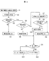
次に、本実施の形態による画面回転動作を図6、図7、図8を参照し、図9のフローチャートに従って説明する。図6は、ラップトップ状態の電子機器を示す斜視図、図7(a)は、画面回転前の斜視図、(b)は、画面回転後の斜視図、図8は、ラップトップ状態の一表示例を示す図である。以下の動作説明において、特に記述がないときはCPU10が行うものとして説明する。
(Screen rotation operation)
Next, the screen rotation operation according to the present embodiment will be described according to the flowchart of FIG. 9 with reference to FIGS. 6 is a perspective view showing an electronic device in a laptop state, FIG. 7A is a perspective view before the screen is rotated, FIG. 6B is a perspective view after the screen is rotated, and FIG. It is a figure which shows the example of a display. In the following description of the operation, the description will be made assuming that the
この電子機器1のユーザが図1(a)に示す見開き状態から図5に示すラップトップ状態に変更したとする。このときは、まだ、第1および第2の画面部4A,4Bに表示されている画面は図1(a)に示す縦向きのままであり、画面は回転されていないため、図6に示す状態において画面は横向きになっている。
It is assumed that the user of the electronic device 1 has changed from the spread state shown in FIG. 1A to the laptop state shown in FIG. At this time, the screens still displayed on the first and
方向センサ16は、常時、電子機器1の方向を検出している(S1)。方向変化検出部17が、所定のタイミング(例えば、5秒間隔)で方向センサ16により検出された方向に基づいて方向の変化を検出し、その結果を検出信号としてCPU10に送信する(S2)。CPU10は、方向変化検出部17からの検出信号に基づいて画面の回転が必要か否かを判断する(S3)。CPU10は、検出された方向変化とRAM12等に記憶されている基準方向変化との比較により画面の回転要・不要を判断する。回転が不要と判断したときは、画面を回転しない(S10)。
The
回転が必要と判断したときは、手動回転モードが設定されている否かを判断する(S5)。手動回転モードは、予め画面部4A,4Bに表示された設定画面でユーザが設定してもよく、カーソルスイッチ7等の操作によって設定してもよい。手動回転モードが設定されていない場合(No)は、CPU10は、ROM11に記憶された画面回転プログラム11aに基づいて図7(a)から図7(b)に示すように画面を90°回転させる(S6)。図7(b)は、画面が横向きから縦向きに90°回転した状態を示す。
When it is determined that the rotation is necessary, it is determined whether or not the manual rotation mode is set (S5). The manual rotation mode may be set by the user on the setting screen displayed in advance on the
ステップS5において、手動回転モードが設定されている場合(Yes)は、回転するか否かの確認画面を第1または第2の画面部4A,4Bに表示し(S7)、回転操作の入力を待つ(S8)。回転操作の入力は、例えば、電子ペン5を用いて行う。一定時間以内に回転操作が入力されない場合(No)は、画面を回転しない(S9)。一定時間以内に回転操作が入力されると(Yes)、図7(b)に示すように画面を90°回転させる(S10)。
In step S5, when the manual rotation mode is set (Yes), a confirmation screen as to whether or not to rotate is displayed on the first or
ステップS6およびS10において、画面を回転した後、キーボードを表示するか否かの判断を行う(S11)。この場合、見開き状態からラップトップ状態への変更であるので、図8に示すように、キーボードを第2の画面部4Bに表示する(S12)。
In steps S6 and S10, after rotating the screen, it is determined whether or not to display the keyboard (S11). In this case, since it is a change from the spread state to the laptop state, the keyboard is displayed on the
見開き状態からラップトップ状態に変更すると、図8に示すように、第1の画面部4Aに設けられた表示エリア100に書籍データ(コンテンツデータ)等が表示される。また、第2の画面部4Bに設けられたキー入力エリア101にキーボードが表示される。キーボードのうち所望のキーに電子ペン5を近づけると、キー入力を行うことができる。第2の画面図4Bには、その他に手書きノートエリア102および手書き文字入力変換エリア103が表示される。手書きノートエリア102は、電子ペン5により描かれた文字をそのまま入力することができるエリアである。手書き文字入力変換エリア103は、電子ペン5により文字を描くと、その文字が自動認識され、その結果が表示されるエリアである。
When the spread state is changed to the laptop state, as shown in FIG. 8, book data (content data) or the like is displayed in the display area 100 provided in the
なお、第1の画面部4Aや第2の画面部4BにWebブラウザによる閲覧画面を表示してもよい。また、筐体2A,2Bにテレビチューナを設け、画面部4A,4Bにテレビの動画等を表示してもよい。
In addition, you may display the browsing screen by a web browser on the
以上の動作説明では、見開き状態からラップトップ状態に変更する場合について説明したが、ラップトップ状態から見開き状態に変更する場合も前述したのと同様に動作するが、上記ステップS11において、画面を回転した後、キーボードを表示しない(S13)。すなわち、キーボードを表示している場合はキーボードを消去する。 In the above description of the operation, the case of changing from the spread state to the laptop state has been described. However, when changing from the laptop state to the spread state, the operation is the same as described above, but in step S11, the screen is rotated. After that, the keyboard is not displayed (S13). That is, when the keyboard is displayed, the keyboard is erased.
(第1の実施の形態の効果)
この第1の実施の形態の電子機器1によれば、以下の効果が得られる。
(イ)見開き状態からラップトップ状態に利用形態を変化させる機能を有しているので、ユーザの利用形態に合わせて多彩な使い勝手を提供することができる。例えば、本電子機器1のHDD15等に大学の教科書等を一式記録させておき、通学時は教科書の閲覧、あるいは趣味の書籍の閲覧を可能とし、授業中はラップトップ状態に利用形態を変化させ、教科書を第1の画面部4Aで見ながら、第2の画面部4B側でノートを取る、計算させる、などといった使い勝手を提供することができる。
(ロ)見開き状態からラップトップ状態に利用形態を変化させたとき、画面を回転させることができるので、利便性に優れた電子機器を提供することができる。
(ハ)設定により自動的に画面を回転させるか手動操作によって画面を回転させるかを選択できるので、寝そべった姿勢など機器1の方向が不安定な場合にも不用意に画面が回転しないため、使いやすい機器となる。
(ニ)見開き機器の特性上、機器の重心位置には制約があるが、本実施の形態のように重心位置構造、接地脚構造を採用することにより、見開き状態からラップトップ状態へと利用形態を容易に変化させることができる。
(ホ)無線により外部と通信が可能であるので、携帯情報端末(PDA:Personal Digital Assistant)としての機能も有することができ、従来の電子書籍、ノート型PC、PDAの3つの機能を1つの機器で実現することができる。
(ヘ)2画面を有するが、折り畳めるので、コンパクトとなり、優れた携帯性が得られる。
(ト)LCD40A,40Bの下にタブレット41A,41Bを配置し、座標入力構造として電磁誘導方式を採用したため、LCD40A,40Bからの表示光がタブレット41A,41Bによって吸収されないため、コントラストの高い画像を表示することができる。また、ペンをコードレスにすることができ、操作性が向上する。さらに、座標検出精度が他の方式と比較して高くなる。
(Effects of the first embodiment)
According to the electronic device 1 of the first embodiment, the following effects can be obtained.
(A) Since it has a function of changing the usage form from the spread state to the laptop state, it is possible to provide various usability according to the usage form of the user. For example, a set of university textbooks, etc., can be recorded on the
(B) Since the screen can be rotated when the usage mode is changed from the spread state to the laptop state, an electronic device with excellent convenience can be provided.
(C) Since it is possible to select whether to rotate the screen automatically or manually according to the setting, the screen will not rotate carelessly even when the orientation of the device 1 is unstable, such as lying down, Easy to use equipment.
(D) Although the center of gravity position of the device is limited due to the characteristics of the spread device, it can be used from the spread state to the laptop state by adopting the center of gravity position structure and the grounding leg structure as in this embodiment. Can be easily changed.
(E) Since it can communicate with the outside wirelessly, it can also have a function as a personal digital assistant (PDA), and it has three functions of a conventional electronic book, notebook PC, and PDA. It can be realized with equipment.
(F) Although it has two screens, it can be folded, resulting in a compact size and excellent portability.
(G) Since the
[第2の実施の形態]
図10は、第2の実施の形態に係る電子機器を示し、同図(a)は、斜視図、同図(b)は、要部断面図である。この第2の実施の形態は、第1の実施の形態の電子ペン5の代りにキートップシート9を用いたものである。このキートップシート9は、通常のキーボードと同様に配置された複数のキートップ90を柔軟な素材で形成されるキー間接続部92によって接続したものであり、全体が一枚のシート状に成型されている。このキートップシート9には、キー支え91が適宜配置されており、キートップ90を第2のLCD40Bから適切な距離を保つように構成されている。
[Second Embodiment]
FIG. 10 shows an electronic apparatus according to the second embodiment, in which FIG. 10A is a perspective view and FIG. In the second embodiment, a key
個々のキートップ90には、図5で説明したものと同様のLC共振回路51が内蔵されており、キートップ90を押すことにより、移動距離分だけLC共振回路51がLCD40Bに近づく。これにより図5で説明したものと同様の原理で、キートップ90の押し込みをタブレット制御部21が検出し、LCD40Bに対応したいずれの位置のキーが押されたかをCPU10に送信し、各種キー入力を可能とする。
Each key top 90 incorporates an LC resonance circuit 51 similar to that described with reference to FIG. 5. By pressing the key top 90, the LC resonance circuit 51 approaches the
キートップ90は、キートップシート9、キー間接続部82と同じ素材で成型されていても良いが、キートップ90の上面だけを硬成型材等で一体成型してもよい。これにより、指の感触などが通常のキーボードに近くなる。
The key top 90 may be formed of the same material as the key
個々のキートップ90に内蔵されているLC共振回路51は、同一の共振周波数のものでも良いが、異なる共振周波数のものを内蔵することにより、他のキーと区別することが容易となり、特定のキー機能を持たせることも可能となる。 The LC resonance circuits 51 incorporated in the individual key tops 90 may have the same resonance frequency, but by incorporating ones having different resonance frequencies, it becomes easy to distinguish from other keys. It is also possible to have a key function.
(第2の実施の形態の効果)
この第2の実施の形態によれば、通常のキーボードと同様にキー入力することができるので、第1の実施の形態の電子ペン5と比較してキー入力操作を容易にすることができる。また、キーボード像の表示を省略することもできる。
(Effect of the second embodiment)
According to the second embodiment, since key input can be performed in the same manner as a normal keyboard, key input operation can be facilitated as compared with the
[他の実施の形態]
なお、本発明は、上記各実施の形態に限定されず、その要旨を変更しない範囲内で種々な変形が可能である。例えば、方向センサを設けずに、ユーザの操作に基づいて画面を回転させてもよい。
[Other embodiments]
The present invention is not limited to the above-described embodiments, and various modifications can be made without departing from the scope of the invention. For example, the screen may be rotated based on the user's operation without providing the direction sensor.
また、方向センサとしては、メカニカルスイッチ,感圧ゴム等を用いてもよい。この場合、方向センサを接地脚に配置し、方向センサが接地を検出した時点で画面の表示方向を切り替えてもよい。 As the direction sensor, a mechanical switch, pressure sensitive rubber, or the like may be used. In this case, the direction sensor may be disposed on the grounding leg, and the display direction of the screen may be switched when the direction sensor detects the grounding.
1 電子機器
2A 第1の筐体
2B 第2の筐体
2a〜2d 接地脚
3 ヒンジ
4A 第1の画面部
4B 第2の画面部
5 電子ペン
6 電源スイッチ
7 カーソルスイッチ
8A 第1のページ送りスイッチ
8B 第2のページ送りスイッチ
9 キートップシート
10 CPU
11 ROM
11a 画面回転プログラム
12 RAM
13 メモリカード
14 カードドライブ
15 HDD
16 方向センサ
17 方向変化検出部
18 通信部
19 スイッチ信号入力部
20 LCD制御部
21 タブレット制御部
30 曲面部
40A 第1のLCD
40B 第2のLCD
41A 第1のタブレット
41B 第2のタブレット
42a 縦コイル
42b 横コイル
50 ペン筐体
51 LC共振回路
52 コイル
53 コンデンサ
80 スイッチ基板
81 スイッチ本体
82 スイッチノブ
82a 突起部
90 キートップ
91 キー支え
92 キー間接続部
100 表示エリア
101 キー入力エリア
102 手書きノートエリア
103 手書き文字入力変換エリア
E 視野角範囲
G1 第1の筐体の重心位置
G2 第2の筐体の重心位置
Lp 垂直線
L1 重心位置G1から垂直線Lpまでの距離
L2 重心位置G2から垂直線Lpまでの距離
W1 第1の筐体の重量
W2 第2の筐体の重量
DESCRIPTION OF SYMBOLS 1
11 ROM
11a
13 Memory card 14 Card drive 15 HDD
16
40B Second LCD
41A 1st tablet 41B 2nd tablet 42a Vertical coil 42b Horizontal coil 50 Pen case 51 LC resonance circuit 52 Coil 53 Capacitor 80 Switch board 81 Switch body 82 Switch knob 82a Protrusion 90 Key top 91
Claims (6)
前記第1および第2の表示部を開閉可能に支持する支持部とを備えたことを特徴とする電子機器。 First and second display units having substantially the same screen size and at least one of which has an input function;
An electronic apparatus comprising: a support portion that supports the first and second display portions so as to be openable and closable.
前記第1あるいは第2の筐体は、少なくとも一方の筐体の姿勢を検知する検知部と、前記姿勢に応じて前記第1および第2の表示部の画面を回転させる制御部とを備えた請求項1記載の電子機器。 The first and second display units are disposed on one surface of the first and second housings supported by the support unit,
The first or second casing includes a detection unit that detects an attitude of at least one of the casings, and a control unit that rotates the screens of the first and second display units according to the attitude. The electronic device according to claim 1.
前記第2の表示部は、前記所定の画像を表示させる命令およびデータを入力する入力部を備えた請求項1記載の電子機器。 The first display unit is a display unit that displays a predetermined image;
The electronic device according to claim 1, wherein the second display unit includes an input unit for inputting a command and data for displaying the predetermined image.
The electronic device according to claim 5, wherein the input unit is detachably provided on the second display unit, and includes a keyboard that incorporates an LC resonance circuit in each key and performs key input by an electromagnetic induction method.
Priority Applications (1)
| Application Number | Priority Date | Filing Date | Title |
|---|---|---|---|
| JP2004075164A JP2005266968A (en) | 2004-03-16 | 2004-03-16 | Electronic equipment |
Applications Claiming Priority (1)
| Application Number | Priority Date | Filing Date | Title |
|---|---|---|---|
| JP2004075164A JP2005266968A (en) | 2004-03-16 | 2004-03-16 | Electronic equipment |
Publications (2)
| Publication Number | Publication Date |
|---|---|
| JP2005266968A true JP2005266968A (en) | 2005-09-29 |
| JP2005266968A5 JP2005266968A5 (en) | 2007-05-10 |
Family
ID=35091486
Family Applications (1)
| Application Number | Title | Priority Date | Filing Date |
|---|---|---|---|
| JP2004075164A Pending JP2005266968A (en) | 2004-03-16 | 2004-03-16 | Electronic equipment |
Country Status (1)
| Country | Link |
|---|---|
| JP (1) | JP2005266968A (en) |
Cited By (19)
| Publication number | Priority date | Publication date | Assignee | Title |
|---|---|---|---|---|
| JP2009146136A (en) * | 2007-12-13 | 2009-07-02 | Kyocera Corp | Information processing device |
| GB2446302B (en) * | 2007-02-07 | 2010-01-06 | Plastic Logic Ltd | Electronic reading devices |
| JP2010066913A (en) * | 2008-09-09 | 2010-03-25 | Nec Personal Products Co Ltd | Information processing apparatus and cursor display control method |
| JP2010066910A (en) * | 2008-09-09 | 2010-03-25 | Nec Personal Products Co Ltd | Information processing apparatus and object display control method |
| JP2010176552A (en) * | 2009-01-30 | 2010-08-12 | Nec Corp | Key input device, small-sized electronic device, key top display method, key top display program and program recording medium |
| JP2010256963A (en) * | 2009-04-21 | 2010-11-11 | Takeshi Ito | Electronic book |
| JP2011014149A (en) * | 2009-07-03 | 2011-01-20 | Sony Corp | Electronic device having rotatable panel configured for display and adaptive interface |
| JP2012003622A (en) * | 2010-06-18 | 2012-01-05 | Toshiba Corp | Electronic apparatus |
| US8203546B2 (en) | 2007-02-07 | 2012-06-19 | Plastic Logic Limited | Electronic document reading devices |
| US8207947B2 (en) | 2007-02-07 | 2012-06-26 | Plastic Logic Limited | Electronic document readers and reading devices |
| US8228323B2 (en) | 2008-03-03 | 2012-07-24 | Plastic Logic Limited | Electronic document reader system |
| JP2012175062A (en) * | 2011-02-24 | 2012-09-10 | Toshiba Corp | Electronic device |
| JP2012190491A (en) * | 2012-07-04 | 2012-10-04 | Toshiba Corp | Electronic apparatus |
| US8539341B2 (en) | 2007-10-24 | 2013-09-17 | Plastic Logic Limited | Electronic document reader |
| JP2013540318A (en) * | 2010-10-01 | 2013-10-31 | ゼット124 | Keyboard that occupies one screen of a multi-screen device or spans multiple screens |
| US8614653B1 (en) * | 2007-10-04 | 2013-12-24 | Leah Salgado | Electronic display device for special events |
| JP2014068355A (en) * | 2010-09-08 | 2014-04-17 | Apple Inc | Camera-based orientation fix from portrait to landscape |
| JP2014071833A (en) * | 2012-10-01 | 2014-04-21 | Toshiba Corp | Electronic apparatus, display change method, display change program |
| JP2020140470A (en) * | 2019-02-28 | 2020-09-03 | レノボ・シンガポール・プライベート・リミテッド | Information processor, control method thereof, and program |
Citations (4)
| Publication number | Priority date | Publication date | Assignee | Title |
|---|---|---|---|---|
| JPH04205340A (en) * | 1990-11-30 | 1992-07-27 | Toshiba Corp | Information processor |
| JPH06215040A (en) * | 1992-11-30 | 1994-08-05 | Toshiba Corp | Information processing system and paging control method |
| JP2003140800A (en) * | 2001-10-29 | 2003-05-16 | Nec Yonezawa Ltd | Portable personal computer |
| JP2004005430A (en) * | 2002-04-11 | 2004-01-08 | Canon Inc | Information processor, its control method, and program |
-
2004
- 2004-03-16 JP JP2004075164A patent/JP2005266968A/en active Pending
Patent Citations (4)
| Publication number | Priority date | Publication date | Assignee | Title |
|---|---|---|---|---|
| JPH04205340A (en) * | 1990-11-30 | 1992-07-27 | Toshiba Corp | Information processor |
| JPH06215040A (en) * | 1992-11-30 | 1994-08-05 | Toshiba Corp | Information processing system and paging control method |
| JP2003140800A (en) * | 2001-10-29 | 2003-05-16 | Nec Yonezawa Ltd | Portable personal computer |
| JP2004005430A (en) * | 2002-04-11 | 2004-01-08 | Canon Inc | Information processor, its control method, and program |
Cited By (27)
| Publication number | Priority date | Publication date | Assignee | Title |
|---|---|---|---|---|
| US8203546B2 (en) | 2007-02-07 | 2012-06-19 | Plastic Logic Limited | Electronic document reading devices |
| GB2446302B (en) * | 2007-02-07 | 2010-01-06 | Plastic Logic Ltd | Electronic reading devices |
| US7920320B2 (en) | 2007-02-07 | 2011-04-05 | Plastic Logic Limited | Electronic reading devices |
| US8207947B2 (en) | 2007-02-07 | 2012-06-26 | Plastic Logic Limited | Electronic document readers and reading devices |
| US8614653B1 (en) * | 2007-10-04 | 2013-12-24 | Leah Salgado | Electronic display device for special events |
| US8836970B2 (en) | 2007-10-24 | 2014-09-16 | Plastic Logic Limited | Document printing techniques |
| US8711395B2 (en) | 2007-10-24 | 2014-04-29 | Plastic Logic Limited | Electronic document reading devices |
| US8539341B2 (en) | 2007-10-24 | 2013-09-17 | Plastic Logic Limited | Electronic document reader |
| JP2009146136A (en) * | 2007-12-13 | 2009-07-02 | Kyocera Corp | Information processing device |
| JP4712786B2 (en) * | 2007-12-13 | 2011-06-29 | 京セラ株式会社 | Information processing device |
| US8228323B2 (en) | 2008-03-03 | 2012-07-24 | Plastic Logic Limited | Electronic document reader system |
| JP2010066913A (en) * | 2008-09-09 | 2010-03-25 | Nec Personal Products Co Ltd | Information processing apparatus and cursor display control method |
| JP2010066910A (en) * | 2008-09-09 | 2010-03-25 | Nec Personal Products Co Ltd | Information processing apparatus and object display control method |
| JP2010176552A (en) * | 2009-01-30 | 2010-08-12 | Nec Corp | Key input device, small-sized electronic device, key top display method, key top display program and program recording medium |
| JP2010256963A (en) * | 2009-04-21 | 2010-11-11 | Takeshi Ito | Electronic book |
| JP2011014149A (en) * | 2009-07-03 | 2011-01-20 | Sony Corp | Electronic device having rotatable panel configured for display and adaptive interface |
| US8934229B2 (en) | 2009-07-03 | 2015-01-13 | Sony Corporation | Electronics device having rotatable panels configured for display and adaptive interface |
| JP2012003622A (en) * | 2010-06-18 | 2012-01-05 | Toshiba Corp | Electronic apparatus |
| JP2014068355A (en) * | 2010-09-08 | 2014-04-17 | Apple Inc | Camera-based orientation fix from portrait to landscape |
| US9565365B2 (en) | 2010-09-08 | 2017-02-07 | Apple Inc. | Camera-based orientation fix from portrait to landscape |
| JP2013540318A (en) * | 2010-10-01 | 2013-10-31 | ゼット124 | Keyboard that occupies one screen of a multi-screen device or spans multiple screens |
| US8405978B2 (en) | 2011-02-24 | 2013-03-26 | Kabushiki Kaisha Toshiba | Electronic device |
| US8755181B2 (en) | 2011-02-24 | 2014-06-17 | Kabushiki Kaisha Toshiba | Electronic device |
| JP2012175062A (en) * | 2011-02-24 | 2012-09-10 | Toshiba Corp | Electronic device |
| JP2012190491A (en) * | 2012-07-04 | 2012-10-04 | Toshiba Corp | Electronic apparatus |
| JP2014071833A (en) * | 2012-10-01 | 2014-04-21 | Toshiba Corp | Electronic apparatus, display change method, display change program |
| JP2020140470A (en) * | 2019-02-28 | 2020-09-03 | レノボ・シンガポール・プライベート・リミテッド | Information processor, control method thereof, and program |
Similar Documents
| Publication | Publication Date | Title |
|---|---|---|
| US11763068B2 (en) | Computing device and browser for same | |
| JP2005266968A (en) | Electronic equipment | |
| EP1886475B1 (en) | Display changing in a portable electronic device | |
| RU2494440C2 (en) | Electronic device with rotary panels arranged for display and adaptive interface | |
| US6788292B1 (en) | Display device | |
| US6930881B2 (en) | Portable computer having a split screen and a multi-purpose hinge | |
| CN101324821B (en) | Portable device | |
| US7170500B2 (en) | Flip-style user interface | |
| US7656661B2 (en) | Electronic apparatus with multiple data input modes | |
| US20070242421A1 (en) | Folding computer | |
| US8102646B2 (en) | Information processing apparatus having switch for inputting key data | |
| EP2039398B1 (en) | Imaging apparatus | |
| WO2007137111A2 (en) | Handheld electronic device with data entry and/or navigation controls on the reverse side of the display | |
| KR20150060278A (en) | Multistage folding display apparatus and function controlling method thereof | |
| EP0793163A2 (en) | Portable computer | |
| JPH07160363A (en) | Portable information processor | |
| JPH11212665A (en) | Thinned computer system | |
| JP2005141715A (en) | Portable terminal device | |
| JP2005275964A (en) | Electronic apparatus | |
| WO2001071518A1 (en) | Electronic briefcase | |
| JP4172035B2 (en) | Portable information device having a plurality of cases | |
| JPH05313786A (en) | Information processor | |
| JP2004185164A (en) | Portable electronic equipment | |
| US20140078659A1 (en) | Portable terminal | |
| JPWO2021054278A5 (en) |
Legal Events
| Date | Code | Title | Description |
|---|---|---|---|
| A521 | Written amendment |
Free format text: JAPANESE INTERMEDIATE CODE: A523 Effective date: 20070315 |
|
| A621 | Written request for application examination |
Free format text: JAPANESE INTERMEDIATE CODE: A621 Effective date: 20070315 |
|
| A977 | Report on retrieval |
Free format text: JAPANESE INTERMEDIATE CODE: A971007 Effective date: 20091022 |
|
| A131 | Notification of reasons for refusal |
Free format text: JAPANESE INTERMEDIATE CODE: A131 Effective date: 20091104 |
|
| A521 | Written amendment |
Free format text: JAPANESE INTERMEDIATE CODE: A523 Effective date: 20091225 |
|
| A02 | Decision of refusal |
Free format text: JAPANESE INTERMEDIATE CODE: A02 Effective date: 20100615 |