JP2005266344A - Zoom lens system - Google Patents
Zoom lens system Download PDFInfo
- Publication number
- JP2005266344A JP2005266344A JP2004079042A JP2004079042A JP2005266344A JP 2005266344 A JP2005266344 A JP 2005266344A JP 2004079042 A JP2004079042 A JP 2004079042A JP 2004079042 A JP2004079042 A JP 2004079042A JP 2005266344 A JP2005266344 A JP 2005266344A
- Authority
- JP
- Japan
- Prior art keywords
- focal length
- lens group
- lens
- lens system
- zoom lens
- Prior art date
- Legal status (The legal status is an assumption and is not a legal conclusion. Google has not performed a legal analysis and makes no representation as to the accuracy of the status listed.)
- Withdrawn
Links
Images


Classifications
-
- G—PHYSICS
- G02—OPTICS
- G02B—OPTICAL ELEMENTS, SYSTEMS OR APPARATUS
- G02B15/00—Optical objectives with means for varying the magnification
- G02B15/14—Optical objectives with means for varying the magnification by axial movement of one or more lenses or groups of lenses relative to the image plane for continuously varying the equivalent focal length of the objective
- G02B15/144—Optical objectives with means for varying the magnification by axial movement of one or more lenses or groups of lenses relative to the image plane for continuously varying the equivalent focal length of the objective having four groups only
- G02B15/1441—Optical objectives with means for varying the magnification by axial movement of one or more lenses or groups of lenses relative to the image plane for continuously varying the equivalent focal length of the objective having four groups only the first group being positive
- G02B15/144105—Optical objectives with means for varying the magnification by axial movement of one or more lenses or groups of lenses relative to the image plane for continuously varying the equivalent focal length of the objective having four groups only the first group being positive arranged +-+-
-
- G—PHYSICS
- G02—OPTICS
- G02B—OPTICAL ELEMENTS, SYSTEMS OR APPARATUS
- G02B15/00—Optical objectives with means for varying the magnification
- G02B15/14—Optical objectives with means for varying the magnification by axial movement of one or more lenses or groups of lenses relative to the image plane for continuously varying the equivalent focal length of the objective
- G02B15/143—Optical objectives with means for varying the magnification by axial movement of one or more lenses or groups of lenses relative to the image plane for continuously varying the equivalent focal length of the objective having three groups only
- G02B15/1431—Optical objectives with means for varying the magnification by axial movement of one or more lenses or groups of lenses relative to the image plane for continuously varying the equivalent focal length of the objective having three groups only the first group being positive
- G02B15/143103—Optical objectives with means for varying the magnification by axial movement of one or more lenses or groups of lenses relative to the image plane for continuously varying the equivalent focal length of the objective having three groups only the first group being positive arranged ++-
Landscapes
- Physics & Mathematics (AREA)
- General Physics & Mathematics (AREA)
- Optics & Photonics (AREA)
- Lenses (AREA)
Abstract
Description
本発明は、写真用カメラ、特に携帯時には撮影レンズをカメラボディ内に収納可能なレンズシャッター式カメラに用いられるズームレンズ系に関する。 The present invention, photographic cameras, and more particularly to a zoom lens system used a taking lens capable of accommodating the lens shutter type camera in the camera body to the portable during.
コンパクトカメラ用のズームレンズ系は、レンズ後方にミラーの配置スペースを要する一眼レフカメラ用のズームレンズ系と異なり、長いバックフォーカスを必要としない。このようなバックフォーカスの制約の少ないズームレンズ系としては、テレフォトタイプ(プラスリーディングレンズ、物体側から順に正負レンズが位置する)が一般的に用いられている。 A zoom lens system for a compact camera does not require a long back focus unlike a zoom lens system for a single-lens reflex camera that requires a mirror arrangement space behind the lens. As the less-restrictive zoom lens system of a back focus, the telephoto type (positive reading lens, negative lens is positioned in this order from the object side) is generally used.
このテレフォトタイプでは、ズーム比(変倍比)が比較的小さい(例えば3〜4倍程度)ときには、物体側から順に、正、正、負の3群タイプが用いられている。
近年では、コンパクトカメラ用のズームレンズ系においても更なる高変倍比化と小型化が望まれている。特許文献1ないし3においても小型でかつ高変倍比を有するズームレンズ系を得ることを目的としているが、いずれも主に、撮影時及び収納時の光軸方向の小型化を課題としており、光軸に垂直な方向、即ちレンズ径方向に小型化するという課題を解決しようとしているものは無かった。
In recent years, high zoom ratio further even in the zoom lens system for a compact camera and miniaturization is desired.
本発明の目的は、3群以上のコンパクトカメラ用のテレフォトタイプズームレンズ系において、一層の小型化、特にレンズ径方向の小型化と高変倍比化の両立を図ることにある。 An object of the present invention is to further reduce the size of a telephoto type zoom lens system for a compact camera of three or more groups, particularly to reduce both the size in the lens radial direction and the high zoom ratio.
従来のテレフォトタイプでは、短焦点距離端から長焦点距離端へのズーミングに際し、正の第1レンズ群から負の最終レンズ群迄の距離が一定か単調に増加していた。この場合、短焦点距離端から長焦点距離端すべての焦点距離領域で必要な周辺光量が確保できるように各レンズ径を定めると、第1レンズ群の最大径を規定するのは画角が最も広い短焦点距離端ではなく中間焦点距離状態であることが発明者の解析により分かった。そこで本発明は、正の第1レンズ群から負の最終レンズ群迄の距離(以下では単に「レンズ全長」又は「LD」という。)が中間焦点距離において最短になるように第1レンズ群を移動すれば、中間焦点距離での周辺光量が確保されることから第1レンズ群を小径化することができ、これによりレンズ径方向の小型化が可能であるとの着眼に基づいて完成されたものである。 In the conventional telephoto type, during the zooming from the short focal length end to the long focal length end, the distance from the positive first lens group to the negative final lens group is constant or monotonously increased. In this case, when each lens diameter is determined so that a necessary peripheral light amount can be secured in all focal length areas from the short focal length end to the long focal length end, the maximum angle of view of the first lens group is defined by the angle of view. The inventor's analysis revealed that the state was an intermediate focal length state rather than a wide short focal length end. Therefore, the present invention sets the first lens group so that the distance from the positive first lens group to the negative final lens group (hereinafter simply referred to as “lens full length” or “LD”) is the shortest at the intermediate focal length. If the lens is moved, the amount of peripheral light at the intermediate focal length is secured, so that the first lens group can be made smaller in diameter, and this has been completed based on the viewpoint that the lens can be reduced in the diameter direction. it is intended.
すなわち、本発明は、ズーミング時に移動するn個(n≧3)のレンズ群を備え、その最も物体側の第1レンズ群が正の屈折力を有し、最も像側の最終レンズ群が負の屈折力を有するズームレンズ系において、第1レンズ群の最も物体側の面から最終レンズ群の最も像側の面迄の距離が、最短焦点距離と最長焦点距離の間の中間焦点距離において最短となることを特徴としている。 That is, the present invention includes n (n ≧ 3) lens groups that move during zooming, the first lens group closest to the object side has positive refractive power, and the final lens group closest to the image side is negative. In the zoom lens system having the refracting power, the distance from the most object side surface of the first lens unit to the most image side surface of the final lens unit is the shortest at the intermediate focal length between the shortest focal length and the longest focal length. It is characterized in that a.
ズームレンズ系は、次の条件式(1)を満足することが好ましい。
(1)1.0<fM/fW<3.0
但し、
fM:第1レンズ群の最も物体側の面から最終レンズ群の最も像側の面迄の距離が最小となる中間焦点距離、
fW:全系の短焦点距離端における焦点距離。
The zoom lens system preferably satisfies the following conditional expression (1).
(1) 1.0 <f M / f W <3.0
However,
f M : an intermediate focal length at which the distance from the most object-side surface of the first lens unit to the most image-side surface of the final lens unit is minimized;
f W : focal length at the short focal length end of the entire system.
またズームレンズ系は、次の条件式(2)を満足することが好ましい。
(2)0.3<(LDW−LDM)/(fT/fW)<1.0
但し、
LDW:短焦点距離端における第1レンズ群の最も物体側の面から最終レンズ群の最も像側の面迄の距離、
LDM:中間焦点距離fMにおける第1レンズ群の最も物体側の面から最終レンズ群の最も像側の面迄の距離、
fT:全系の長焦点距離端における焦点距離。
The zoom lens system preferably satisfies the following conditional expression (2).
(2) 0.3 <(LD W −LD M ) / (f T / f W ) <1.0
However,
LD W : Distance from the most object side surface of the first lens unit to the most image side surface of the final lens unit at the short focal length end,
LD M : Distance from the most object side surface of the first lens unit to the most image side surface of the last lens unit at the intermediate focal length f M
f T : focal length at the long focal length end of the entire system.
条件式(1)、(2)を満足することにより、第1レンズ群の小径化を達成することができる。 Condition (1), by satisfying the expression (2), it is possible to achieve a small diameter of the first lens group.
またズームレンズ系は、高ズーム比(変倍比)を確保しつつ収差補正を良好に行えるように、次の条件式(3)又は/及び(4)を満足することが好ましい。
(3)0<LDT−LDW
(4)0.3<(LDT−LDW)/(fT/fW)<0.9
但し、
LDT:長焦点距離端における第1レンズ群の最も物体側の面から最終レンズ群の最も像側の面迄の距離。
Further, it is preferable that the zoom lens system satisfies the following conditional expression (3) or / and (4) so that aberration correction can be favorably performed while ensuring a high zoom ratio (magnification ratio).
(3) 0 <LD T -LD W
(4) 0.3 <(LD T −LD W ) / (f T / f W ) <0.9
However,
LD T : Distance from the most object side surface of the first lens unit to the most image side surface of the last lens unit at the long focal length end.
さらにズームレンズ系は、次の条件式(5)を満足することが好ましい。
(5)3<fT/fW
この条件式(5)を満足することで高変倍比化を達成することができる。
Furthermore, it is preferable that the zoom lens system satisfies the following conditional expression (5).
(5) 3 <f T / f W
A high zoom ratio can be achieved by satisfying this conditional expression (5).
上記ズームレンズ系が3群構成(n=3)である場合は、物体側から順に、正の屈折力を有する第1レンズ群、正の屈折力を有する第2レンズ群、及び負の屈折力を有する第3レンズ群となる。また上記ズームレンズ系が4群構成(n=4)である場合には、物体側から順に、正の屈折力を有する第1レンズ群、負の屈折力を有する第2レンズ群、正の屈折力を有する第3レンズ群及び負の屈折力を有する第4レンズ群となる。 When the zoom lens system has a three-group configuration (n = 3), in order from the object side, a first lens group having a positive refractive power, a second lens group having a positive refractive power, and a negative refractive power a third lens group having a. When the zoom lens system has a four-group configuration (n = 4), in order from the object side, a first lens group having a positive refractive power, a second lens group having a negative refractive power, and a positive refraction. A third lens group having power and a fourth lens group having negative refractive power are obtained.
4群構成のズームレンズ系は、次の条件式(6)を満足することが好ましい。
(6)1.2<fM/fW<3.0
It is preferable that the zoom lens system having a four-group configuration satisfies the following conditional expression (6).
(6) 1.2 <f M / f W <3.0
また4群構成のズームレンズ系は、次の条件式(7)を満足することが好ましい。
(7)0.3<(LDT−LDW)/(fT/fW)<0.7
In addition, it is preferable that the zoom lens system having a four-group configuration satisfies the following conditional expression (7).
(7) 0.3 <(LD T −LD W ) / (f T / f W ) <0.7
さらに4群構成ズームレンズ系は、次の条件式(8)を満足することが好ましい。
(8)0.3<(d23W−d23T)/(fT/fW)<1.5
但し、
d23W:短焦点距離端での第2レンズ群と第3レンズ群の軸上空気間隔、
d23T:長焦点距離端での第2レンズ群と第3レンズ群の軸上空気間隔。
条件式(8)を満足することにより、レンズ全長の増大を防ぎながら高ズーム比が得られる。
Furthermore, it is preferable that the four-group zoom lens system satisfies the following conditional expression (8).
(8) 0.3 <(d 23W −d 23T ) / (f T / f W ) <1.5
However,
d23W : axial air space between the second lens unit and the third lens unit at the short focal length end,
d 23T : On-axis air space between the second lens group and the third lens group at the long focal length end.
By satisfying conditional expression (8), a high zoom ratio can be obtained while preventing an increase in the total lens length.
4群構成のズームレンズ系は、第2レンズ群の移動量を抑えることによりコンパクト化(撮影時及び収納時の光軸方向の小型化)を図ることができる。第2レンズ群の移動量を抑えるためには、次の条件式(9)を満足することが好ましい。
(9)−12<fT/f2G<−9
但し、
f2G:第2レンズ群の焦点距離。
The zoom lens system having a four-group configuration can be made compact (downsizing in the optical axis direction during shooting and storage) by suppressing the amount of movement of the second lens group. In order to suppress the movement amount of the second lens group, it is preferable that the following conditional expression (9) is satisfied.
(9) -12 <f T / f 2G <-9
However,
f 2G: focal length of the second lens group.
また4群構成のズームレンズ系は、次の条件式(10)を満足することが好ましい。
(10)1.05<h3G/h1<1.30
但し、
h3G:第3レンズ群の最終面に入射する近軸光線の高さh、
h1:第1レンズ群の第1面に入射する近軸光線の高さh。
この条件を満たすことで半画角35゜以上の広角化を達成し、短焦点距離端(W)でのバックフォーカスを確保することができる。
In addition, it is preferable that the zoom lens system having a four-group configuration satisfies the following conditional expression (10).
(10) 1.05 <h 3G / h 1 <1.30
However,
h 3G : the height h of the paraxial ray incident on the final surface of the third lens group,
h 1 : The height h of the paraxial ray incident on the first surface of the first lens group.
By satisfying this condition, a wide angle of a half angle of view of 35 ° or more can be achieved, and a back focus at the short focal length end (W) can be secured.
また4群構成のズームレンズ系は、高変倍比化を達成するため、次の条件式(11)を満足することが好ましい。
(11)4.5<fT/fW
The zoom lens system having a four-group configuration preferably satisfies the following conditional expression (11) in order to achieve a high zoom ratio.
(11) 4.5 <f T / f W
4群構成のズームレンズ系において、第2レンズ群は、次の条件式(12)を満足する非球面を少なくとも一面有するレンズを含むことが好ましい。
(12)3<ΔI(2G)asp<9
但し、
ΔI(2G)asp:短焦点距離端の焦点距離を1.0に換算したときの非球面による球面収差係数の変化量。
この条件を満たすことにより、レンズ移動量を抑えるために第2レンズ群のパワーを大きくしたときにも、レンズ枚数を増やさずに群収差の補正を行うことができる。
In the zoom lens system having a four-group structure, it is preferable that the second lens group includes a lens having at least one aspherical surface that satisfies the following conditional expression (12).
(12) 3 <ΔI (2G) asp <9
However,
ΔI (2G) asp: The amount of change in the spherical aberration coefficient due to the aspherical surface when the focal length at the short focal length end is converted to 1.0.
By satisfying this condition, it is possible to correct the group aberration without increasing the number of lenses even when the power of the second lens group is increased in order to suppress the lens movement amount.
4群構成のズームレンズ系において、第3レンズ群は、次の条件式(13)を満足する非球面を少なくとも一面有するレンズを含むことが好ましい。
(13)−40<ΔI(3G)asp<−10
但し、
ΔI(3G)asp:短焦点距離端の焦点距離を1.0に換算したときの非球面による球面収差係数の変化量。
この条件を満たすことで第3レンズ群のレンズ枚数が減少し、特に球面収差を良好に補正することができる。
In the zoom lens system having a four-group configuration, it is preferable that the third lens group includes a lens having at least one aspherical surface that satisfies the following conditional expression (13).
(13) −40 <ΔI (3G) asp <−10
However,
ΔI (3G) asp: The amount of change in spherical aberration coefficient due to the aspherical surface when the focal length at the short focal length end is converted to 1.0.
By satisfying this condition, the number of lenses in the third lens group is reduced, and in particular, spherical aberration can be corrected well.
3群以上のズームレンズ系において、負の屈折力を有する最終レンズ群は、次の条件式(14)を満足する非球面を少なくとも一面有するレンズを含むことが好ましい。
(14)0<ΔVasp<3
但し、
ΔVasp:短焦点距離端の焦点距離を1.0に換算したときの非球面による球面収差係数の変化量。
この条件を満たすことにより、最終レンズ群のレンズ枚数が減少し、特に短焦点距離端での歪曲収差を良好に補正することができる。
In the zoom lens system including three or more groups, it is preferable that the final lens group having negative refractive power includes a lens having at least one aspherical surface that satisfies the following conditional expression (14).
(14) 0 <ΔVasp <3
However,
ΔVasp: A change amount of the spherical aberration coefficient due to the aspherical surface when the focal length at the short focal length end is converted to 1.0.
By satisfying this condition, the number of lenses in the final lens group can be reduced, and distortion at the short focal length end can be corrected well.
本発明によれば、3群以上のプラスリーディングのテレフォトタイプのズームレンズ系において、一層の小径化、特にレンズ径方向の小型化と高変倍比化の両立を図ることができる。 According to the present invention, in a plus-reading telephoto type zoom lens system of three or more groups, it is possible to achieve further reduction in diameter, particularly reduction in size in the lens radial direction and high zoom ratio.
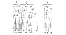
図1は、本発明を適用した3群タイプのテレフォトタイプズームレンズ系の簡易移動図である。すなわち、3群タイプは、物体側から順に、正のパワーの第1レンズ群10、絞りS、正のパワーの第2レンズ群20及び負のパワーの第3レンズ群30からなっている。Iは像面を示す。短焦点距離端(W)から長焦点距離端(T)へのズーミングに際し、正の第1レンズ群10は図1に破線で示す第3レンズ群の移動軌跡と平行な移動軌跡(ズーミングに際してLDが一定となる移動軌跡)よりも一旦像側に移動してから物体側に移動し、正の第2レンズ群20及び負の第3レンズ群30は単調に物体側へ移動する。このとき、第1レンズ群10と第2レンズ群20の間隔は一旦縮まって再び増加し、第2レンズ群20と第3レンズ群30の間隔は減少する。絞りSは第2レンズ群20と一緒に移動する。この結果、第1レンズ群10の最も物体側の面(第1面)から第3レンズ群(最終レンズ群)30の最も像側の面(最終面)までの距離は、短焦点距離端(W)において最短にならず、短焦点距離端(W)から長焦点距離端(T)の間の中間焦点距離fMにおいて最短になる。
FIG. 1 is a simple movement diagram of a three-group telephoto type zoom lens system to which the present invention is applied. That is, 3-group type is composed of, in order from the object side, a
図2は、本発明を適用した4群タイプのテレフォトタイプズームレンズ系の簡易移動図である。すなわち、4群タイプは、物体側から順に、正のパワーの第1レンズ群40、負のパワーの第2レンズ群50、正のパワーの第3レンズ群60、絞りS及び負のパワーの第4レンズ群70からなっている。Iは像面を示す。短焦点距離端(W)から長焦点距離端(T)へのズーミングに際し、正の第1レンズ群40は図2に破線で示す第4レンズ群の移動軌跡と平行な移動軌跡(ズーミングに際してLDが一定となる移動軌跡)よりも一旦像側に移動してから物体側に移動し、負の第2レンズ群50、正の第3レンズ群60及び負の第4レンズ群70は単調に物体側に移動する。このとき、第1レンズ群40と第2レンズ群50の間隔は一旦縮まって再び増加し、第2レンズ群50と第3レンズ群60の間隔は単調に減少し、第3レンズ群60と第4レンズ群70の間隔は単調に減少する。絞りSは第3レンズ群60と一緒に移動する。この結果、第1レンズ群40の最も物体側の面(第1面)から第4レンズ群(最終レンズ群)70の最も像側の面(最終面)までの距離は、短焦点距離端(W)において最短にならず、短焦点距離端(W)から長焦点距離端(T)の間の中間焦点距離fMにおいて最短になる。
FIG. 2 is a simplified movement diagram of a four-group telephoto type zoom lens system to which the present invention is applied. That is, 4-group type is composed of, in order from the object side, a positive first
図3は、本発明を適用した4群タイプのテレフォトタイプズームレンズ系の簡易移動図であって、切替移動のある移動軌跡の例である。この4群タイプは、物体側から順に、正のパワーの第1レンズ群80、負のパワーの第2レンズ群90、正のパワーの第3レンズ群100、絞りS及び負のパワーの第4レンズ群110からなっている。Iは像面を示す。短焦点距離端(W)から長焦点距離端(T)へのズーミングに際し、第1レンズ群80は短焦点距離端(W)から焦点距離fm1までの焦点距離域ZWの途中の中間焦点距離fMで図3に破線で示す第4レンズ群と平行な移動軌跡(ズーミングに際してLDが一定となる移動軌跡)よりも一旦像側に移動してから物体側に移動し、第2レンズ群90、第3レンズ群100及び第4レンズ群110は短焦点距離端(W)から焦点距離fm1までの焦点距離域ZWで共に物体側に移動する。そして第1レンズ群80、第2レンズ群90、第3レンズ群100及び第4レンズ群110は、焦点距離fm1において所定の距離だけ像側に移動して切替後焦点距離fm2となり、さらに切替後焦点距離fm2から長焦点距離端(T)までの焦点距離域ZTで共に物体側に移動する。また、第2レンズ群90と第3レンズ群100は、焦点距離域ZWでその間隔を一定(d1)に保持し、焦点距離fm1においてその間隔を狭め(d2)、さらに焦点距離域ZTでその狭めた間隔(d2)を保持する。焦点距離fm1は焦点距離域ZWに属し、切替後焦点距離fm2は焦点距離fm1において第1レンズ群80と第4レンズ群110が像側へ移動し、かつ第2レンズ群90と第3レンズ群100が間隔を狭めたときの焦点距離である。絞りSは、第3レンズ群100と第4レンズ群110の間に位置し、ズーミングに際し第3レンズ群100とともに移動する。この結果、第1レンズ群80の最も物体側の面(第1面)から第4レンズ群(最終レンズ群)110の最も像側の面(最終面)までの距離は、短焦点距離端(W)において最短にならず、短焦点距離端(W)から長焦点距離端(T)の間の中間焦点距離fMにおいて最短になる。
FIG. 3 is a simple movement diagram of a telephoto type zoom lens system of the four-group type to which the present invention is applied, and is an example of a movement locus with switching movement. The 4-group type is composed of, in order from the object side, a
このように、第1レンズ群の第1面から最終レンズ群の最終面までの距離LDが短焦点距離端(W)で最短にならず、中間焦点距離fMにおいて最短になるようにズーミング基礎軌跡を定めると、中間焦点距離fMにおける最周辺光束(最大像高に向かう光束)の第1レンズ群通過高さが下がるので短焦点距離fWにおいて第1レンズ群に最も高い光線が通過することとなり、第1レンズ群の径、ひいては全系の径を縮小することができる。これにより、レンズ径方向の小型化を図れる。さらに、全系の径を縮小することでレンズ厚も小さくでき、レンズ群が薄くなりひいては収納長の短縮(カメラの薄型化)も図ることができる。 Thus, the distance LD from the first surface of the first lens group to the last surface of the last lens unit is not the shortest at the short focal length end (W), zooming basis as the shortest in the intermediate focal length f M When defining the locus, the highest light on the first lens group in the intermediate focal length f since the first lens group passes the height of the outermost peripheral light (light beam proceeding to the maximum image height) decreases in M short focal length f W passes In other words, the diameter of the first lens group, and thus the diameter of the entire system can be reduced. Thereby, size reduction in the lens radial direction can be achieved. Further, by reducing the diameter of the entire system, the lens thickness can also be reduced, and the lens group can be thinned and the storage length can be shortened (thinner camera can be made thinner).
図29ないし図31は、レンズ全長(LD=TL-FB)を、短焦点距離端(W)で最短とする場合と、中間焦点距離fMで最短とする場合とを比較して描いた図である。図29は本願実施例1(詳しくは後述)によるズームレンズ系の短焦点距離端(W)f=39.000におけるレンズ構成図、図30は図29のズームレンズ系を、短焦点距離端(W)でレンズ全長が最短となる従来の移動軌跡で焦点距離f=50.000にズーミングした時のレンズ構成図、図31は図29のズームレンズ系を、短焦点距離端(W)と長焦点距離端(T)との間の中間焦点距離fMでレンズ全長が最短となる本願発明の移動軌跡で焦点距離f=50.000にズーミングした時のレンズ構成図である。いずれの図においても、FNOで決まる軸上光束と最大像高(y=21.64)の光束が描かれている。また図30及び図31では、各最大像高における周辺光量が同じになるように上光線と下光線を決定している。図30と図31を見ると、最大像高の光束が第1レンズ群の最も物体側の面を通過する時の光軸からの高さaは、本願実施例の移動軌跡でズーミングさせた場合(図31)のほうが、従来の移動軌跡でズーミングさせた場合(図30)よりも明らかに低いことが分かる。また、最大像高の光束が第1レンズ群の最も物体側の面を通過する時の光軸からの高さaは、従来の移動軌跡でズーミングさせた場合は短焦点距離端(W)よりも焦点距離50.000で高くなるのに対し、本願実施例の移動軌跡でズーミングさせた場合は短焦点距離端(W)よりも焦点距離50.000で低くなっている。従って、本願実施例のようにレンズ全長(LD)が中間焦点距離fMで最短となるようにズーミング移動軌跡を設定すれば、第1レンズ群を通過する最周辺光束の高さは最も画角の広い短焦点距離端で最大となり、長焦点距離端に向かうにつれて第1レンズ群の最も物体側の面に入射する光束の高さaをより低くなるため、周辺光量を確保しつつ第1レンズ群の径を従来よりも小さくすることができる。第1レンズ群を小径化すれば、全系の径を縮小することで、レンズ径方向の小型化を図れると共にレンズ厚を小さくして薄型化(光軸方向の小型化)も図ることができる。 FIGS. 29 to 31 are diagrams comparing the case where the total lens length (LD = TL-FB) is the shortest at the short focal length end (W) with the case where the total focal length f M is the shortest. it is. FIG. 29 is a lens configuration diagram at the short focal length end (W) f = 39.000 of the zoom lens system according to Embodiment 1 (details will be described later), and FIG. 30 shows the zoom lens system of FIG. 29 at the short focal length end (W). in lens arrangement when the zooming the focal length f = 50.000 in the conventional moving track the total lens length is shortest, FIG. 31 the zoom lens system of FIG. 29, the short focal length end (W) and the long focal length end ( FIG. 6 is a lens configuration diagram when zooming to a focal length f = 50.000 on the movement locus of the present invention in which the total lens length is the shortest at an intermediate focal length f M between T and T). In either figure, the light flux of the axial light flux and the maximum image height determined by F NO (y = 21.64) is depicted. In FIGS. 30 and 31, the upper ray and the lower ray are determined so that the peripheral light amount at each maximum image height is the same. Turning to FIGS. 30 and 31, when the light beam of the maximum image height is the height a from the optical axis as it passes through the surface closest to the object side in the first lens group, which was zooming locus of movement of the present embodiment It can be seen that (FIG. 31) is clearly lower than the case of zooming with the conventional movement locus (FIG. 30). Further, the height a from the optical axis when the light beam having the maximum image height passes through the most object-side surface of the first lens group is shorter than the short focal length end (W) when zooming is performed with the conventional movement locus. Is higher at a focal length of 50.000, whereas when zooming is performed with the movement trajectory of the present embodiment, the focal length is lower than the short focal length end (W) at a focal length of 50.000. Therefore, by setting the zooming movement trajectory so that the lens total length (LD) is the shortest in the intermediate focal length f M as in the present embodiment, the height of the outermost peripheral light flux passing through the first lens group and most angle maximum at wide short focal length end, to become lower the height a of the light beam incident on the most object side surface of the first lens group toward the long focal length end, the first lens while securing the peripheral light amount it is possible to reduce the diameter of the group than before. If the diameter of the first lens group is reduced, by reducing the diameter of the entire system, it is possible to reduce the size in the lens radial direction and to reduce the lens thickness and to reduce the thickness (to reduce the optical axis direction). .
条件式(1)〜(5)及び(14)は、レンズ構成が3群以上である場合の条件である。 Condition (1) to (5) and (14) is a condition when the lens structure is not less than 3 group.
条件式(1)は、第1レンズ群の径を小さくするために最適な、レンズ全長LDを最短とする中間焦点距離fMを定めている。
条件式(1)の上限を超えると、レンズ全長LDを最短とする中間焦点距離fMが短焦点距離端(W)に近づき過ぎ、条件式(1)の下限を超えると中間焦点距離fMが長焦点距離端(T)に近づき過ぎてしまう。いずれの場合にも、第1レンズ群の小径化の効果が期待できない。
Condition (1) is optimal, and the total lens length LD defines the intermediate focal length f M of the shortest in order to reduce the diameter of the first lens group.
If the upper limit of conditional expression (1) is exceeded, the intermediate focal length f M that makes the lens total length LD the shortest is too close to the short focal length end (W), and if the lower limit of conditional expression (1) is exceeded, the intermediate focal length f M is exceeded. Becomes too close to the long focal length end (T). In either case, the effect of reducing the diameter of the first lens group cannot be expected.
条件式(2)は、中間焦点距離fMでレンズ全長LDを最短とする効果的な条件を定めている。
条件式(2)の上限を超えると、中間焦点距離fMにおいてレンズ全長LDが短くなりすぎ、収差補正が困難になる。条件式(2)の下限を超えると、中間焦点距離fMと短焦点距離端(W)でのレンズ全長の差が小さくなり、第1レンズ群の小径化の効果が減少する。
Condition (2) defines the conditions effective for the total lens length LD shortest in the intermediate focal length f M.
If the upper limit of conditional expression (2) is exceeded, the total lens length LD becomes too short at the intermediate focal length f M , and aberration correction becomes difficult. When the lower limit of conditional expression (2) is exceeded, the difference between the total lens length at the intermediate focal length f M and the short focal length end (W) becomes small, and the effect of reducing the diameter of the first lens group decreases.
条件式(3)は、短焦点距離端(W)及び長焦点距離端(T)でのレンズ全長LDに関するもので、ズーム比(変倍比)を大きくしつつ、収差補正を良好に行なうための条件である。
条件式(3)の下限を超えると、すなわち長焦点距離端でのレンズ全長が短焦点距離端でのレンズ全長以下になると、各レンズ群の移動量に制約ができるため、高変倍比化できなくなる。低変倍比の光学系に本願を適用することは勿論可能であるが、適用意義がほとんど無い。
Condition (3) relates to the total lens length LD at the short focal length end (W) and the long focal length end (T), while increasing the zoom ratio (variable power ratio), to perform the aberration correction better it is a condition.
If the lower limit of conditional expression (3) is exceeded, that is, if the total lens length at the long focal length end is less than or equal to the total lens length at the short focal length end, the amount of movement of each lens group can be constrained. become unable. Of course, the present application can be applied to an optical system having a low zoom ratio, but there is almost no application significance.
条件式(4)は、短焦点距離端(W)から長焦点距離端(T)までのレンズ全長LDの変化量に関するもので、ズーム比(変倍比)を大きくしつつ、収差補正を良好に行なうための条件である。
条件式(4)の上限を超えると、各レンズ群の移動量が大きくなり、光学的には高変倍比化と収差補正に有利であるが長焦点距離端(T)側のレンズ全長LDが長くなりすぎ、メカ構成が困難となる。条件式(4)の下限を超えると、各レンズ群の移動量を十分確保することが困難となり、無理に高変倍比化しようとすれば各群のパワーが強くなり、特に長焦点距離端(T)側の収差補正が困難になる。非球面等で光学的には補正できたとしても、各レンズ群が高い組立誤差感度を有するので、実用的とは言えない。
Condition (4) relates to the amount of change in total lens length LD from the short focal length end (W) to the long focal length end (T), while increasing the zoom ratio (variable power ratio), good aberration correction It is a condition for performing.
If the upper limit of condition (4), the moving amount of each lens group becomes large, the optical high zoom ratio and aberration preference is but long focal length end to a correction (T) side of the lens length LD is too long, mechanical structure becomes difficult. If the lower limit of conditional expression (4) is exceeded, it will be difficult to secure a sufficient amount of movement for each lens group, and the power of each group will become stronger if an attempt is made to increase the zoom ratio forcibly. It becomes difficult to correct the aberration on the (T) side. Even if it can be optically corrected with an aspherical surface or the like, each lens group has a high assembly error sensitivity, which is not practical.
条件式(5)は、ズームレンズ系の全系の変倍比を定めている。
条件式(5)の下限を下回るような低変倍比の光学系に対して本願構成を採ることは不可能ではないが、適用意義はほとんど無い。
Conditional expression (5) defines the zoom ratio of the entire zoom lens system.
Although it is not impossible to adopt the configuration of the present application for an optical system with a low zoom ratio that falls below the lower limit of conditional expression (5), there is almost no application significance.
条件式(6)〜(13)は、レンズ構成が4群構成(つまり、物体側から順に正負正負)である場合の条件である。 Condition (6) - (13), the lens arrangement 4-group configuration (i.e., positive and negative polarity in order from the object side) is a condition where it is.
条件式(6)は、第1レンズ群の径を小さくするために最適な、レンズ全長を最短とする中間焦点距離fMを定めている。
条件式(6)の上限又は下限を超えると、中間焦点距離fMが短焦点距離端(W)又は長焦点距離端(T)に近づき過ぎ、第1レンズ群の小径化による効果が期待できない。条件式(1)に比べて下限側が狭くなっているのは、4群構成の場合、より高変倍比化が容易となるが、その場合にはfMを3群構成の場合よりやや長焦点距離端側に設定した方が第1レンズ群の小径化に有利だからである。
Conditional expression (6) defines an intermediate focal length f M that is optimal for reducing the diameter of the first lens group and that minimizes the total lens length.
When the upper limit or lower limit of conditional expression (6) is exceeded, the intermediate focal length f M becomes too close to the short focal length end (W) or the long focal length end (T), and the effect of reducing the diameter of the first lens group cannot be expected. . The lower limit side is narrower than that in the conditional expression (1). In the case of the four-group configuration, it becomes easier to achieve a higher zoom ratio. In that case, however, fM is slightly longer in focus than in the case of the three-group configuration. This is because setting to the distance end side is advantageous for reducing the diameter of the first lens group.
条件式(7)は、短焦点距離端(W)から長焦点距離端(T)までのレンズ全長LDの変化量に関するもので、ズーム比(変倍比)を大きくしつつ、収差補正を良好に行なうための条件である。
条件式(7)の上限を超えると、各レンズ群の移動量が大きくなり、光学的には高変倍比化と収差補正に有利であるが長焦点距離端(T)側のレンズ全長LDが長くなりすぎ、メカ構成が困難となる。条件式(7)の下限を超えると、各レンズ群の移動量を十分確保することが困難となり、特に長焦点距離端(T)側の収差補正が困難になる。非球面等で光学的には補正できたとしても、各レンズ群が高い組立誤差感度を有するので、実用的とは言えない。条件式(4)に比べて上限側が狭くなっているのは、4群構成の場合、ズーミングの為に移動できるレンズ群が多いので、レンズ全長の変化が少なくても効果が得られるからである。
Condition (7) relates to the amount of change in total lens length LD from the short focal length end (W) to the long focal length end (T), while increasing the zoom ratio (variable power ratio), good aberration correction It is a condition for performing.
If the upper limit of condition (7), the moving amount of each lens group becomes large, the optical high zoom ratio and aberration preference is but long focal length end to a correction (T) side of the lens length LD Becomes too long and the mechanical structure becomes difficult. If the lower limit of conditional expression (7) is exceeded, it will be difficult to ensure a sufficient amount of movement for each lens group, and it will be particularly difficult to correct aberrations on the long focal length end (T) side. Even if it can be optically corrected with an aspherical surface or the like, each lens group has a high assembly error sensitivity, which is not practical. The reason why the upper limit side is narrower than the conditional expression (4) is that, in the case of the four-group configuration, since there are many lens groups that can be moved for zooming, the effect can be obtained even if there is little change in the total lens length. .
条件式(8)は、第2レンズ群と第3レンズ群の群間隔変化量に関するもので、レンズ全長の増大を防ぎながら、変倍比(ズーム比)を大きくするための条件である。
条件式(8)の上限を超えると、第2レンズ群と第3レンズ群の群間隔変化量が大きくなり、収差補正と高変倍比化には有利であるがレンズ全長が長くなって好ましくない。条件式(8)の下限を超えると、第2レンズ群、第3レンズ群の群間隔変化量が小さく、第2、第3レンズ群による変倍効果が弱くなり、4群構成としての十分な変倍効果が得られない。
Condition (8) relates to the group spacing variation of the second lens group and the third lens group, while preventing an increase in the total lens length is a condition for increasing the zoom ratio (zoom ratio).
When the upper limit of conditional expression (8) is exceeded, the amount of change in the group interval between the second lens group and the third lens group becomes large, which is advantageous for aberration correction and high zoom ratio, but the total lens length is preferably long. Absent. When the lower limit of conditional expression (8) is exceeded, the amount of change in the group interval between the second lens group and the third lens group is small, and the zooming effect by the second and third lens groups is weakened, which is sufficient as a four-group configuration. The zoom effect cannot be obtained.
条件式(9)は、第2レンズ群の焦点距離に関する条件である。この条件を満たすことにより、第2レンズ群に最適なパワーを配置することができ、高変倍比化した時にも第2レンズ群の移動量を抑え、コンパクト化を図ることができる。
条件式(9)の下限を超えると、第2レンズ群のパワーが強くなりすぎ、該第2レンズ群の持つ収差が大きくなって変倍による収差変動を補正することが困難になる。条件式(9)の上限を超えると、第2レンズ群のパワーが小さくなりすぎ、高変倍比化すると第2レンズ群の移動量が大きくなってコンパクト化が図れない。
Conditional expression (9) is a condition relating to the focal length of the second lens group. By satisfying this condition, it is possible to arrange the optimum power for the second lens group, and it is possible to reduce the amount of movement of the second lens group even when the zoom ratio is increased and to achieve a compact size.
When the lower limit of the conditional expression (9), too strong a power of the second lens group, it becomes difficult to correct the aberration variation due to zooming aberration possessed by the second lens group becomes large. If the upper limit of conditional expression (9) is exceeded, the power of the second lens group will be too small, and if the zoom ratio is increased, the amount of movement of the second lens group will be large and compactness cannot be achieved.
条件式(10)は、第3レンズ群の最終面の近軸h(近軸光束の最周辺光が通過する点の光軸からの高さ)と第1レンズ群の第1面の近軸hの比に関する条件で、この条件を満たすことで短焦点距離端において半画角35゜以上の広角化(短焦点距離化)をしながら、短焦点距離端(W)でのバックフォーカスを確保することができる。条件式(10)の上限を超えると、第1レンズ群から第3レンズ群までの収差補正が困難になり、収差補正を良好に行なうためにはレンズ枚数が増えて大型化する。条件式(10)の下限を超えると、半画角35°以上とした時バックフォーカスを確保することが困難になる。バックフォーカスが短くなりすぎると第4レンズ群のレンズ径が大きくなり過ぎ、本願発明による第1レンズ群のレンズ径を小さくする効果の意味が薄れてしまうと共に、最も像面側のレンズ面に付着した異物等の影が像面に達してしまうという問題が発生する。 Conditional expression (10) is that the paraxial h of the final surface of the third lens group (the height from the optical axis of the point where the most peripheral light of the paraxial light beam passes) and the paraxial of the first surface of the first lens group. By satisfying this condition with respect to the ratio of h, the back focal length at the short focal length end (W) is secured while widening (short focal length) with a half field angle of 35 ° or more at the short focal length end. can do. If the upper limit of conditional expression (10) is exceeded, it will be difficult to correct aberrations from the first lens group to the third lens group, and the number of lenses will increase and the size will increase in order to perform aberration correction satisfactorily. When the lower limit of the conditional expression (10), it becomes difficult to ensure the back focus when the half angle of 35 ° or more. If the back focus becomes too short, the lens diameter of the fourth lens group becomes too large, and the meaning of the effect of reducing the lens diameter of the first lens group according to the present invention is diminished, and it adheres to the lens surface closest to the image plane. There arises a problem that the shadow of the foreign matter or the like that has reached the image plane.
条件式(11)は、ズームレンズ系の全系の変倍比を定めている。条件式(11)の下限を下回るような光学系に対しても本願構成を採ることは可能であるが、その意義はほとんど無い。 Conditional expression (11) defines the zoom ratio of the entire zoom lens system. It is possible to take the present configuration even for an optical system such as a lower limit of conditional expression (11), its significance is little.
条件式(12)は、レンズ移動量を抑えるために第2レンズ群のパワーを大きくしたときレンズ枚数を増やさずに群収差の補正を行えるように、第2レンズ群中に少なくとも一面の非球面を用いる場合の非球面量に関する条件である。この条件を満たすことで、特に球面収差を良好に補正することができる。
条件式(12)の上限を超えると、非球面量が大きくなり、製造困難である。条件式(12)の下限を超えると、非球面による球面収差補正効果が十分に得られない。
Condition (12), to allow the correction of the groups aberration without increasing the number of lenses when large power of the second lens group in order to suppress the amount of lens movement, at least one aspheric surface in the second lens group which is a condition relating to aspherical amount when used. By satisfying this condition, particularly spherical aberration can be corrected satisfactorily.
If the upper limit of conditional expression (12) is exceeded, the amount of aspherical surface becomes large and it is difficult to manufacture. If the lower limit of conditional expression (12) is exceeded, the effect of correcting spherical aberration by an aspherical surface cannot be obtained sufficiently.
条件式(13)は、球面収差を補正するために、第3レンズ群中に少なくとも一面の非球面を用いる場合の非球面量に関する条件である。
条件式(13)の上限を超えると、非球面による球面収差補正効果が十分に得られない。条件式(13)の下限を超えると、非球面量が大きくなり、製造困難となる。
Conditional expression (13) is a condition relating to the amount of aspheric surface when at least one aspheric surface is used in the third lens group in order to correct spherical aberration.
If the upper limit of conditional expression (13) is exceeded, the effect of correcting spherical aberration by an aspherical surface cannot be obtained sufficiently. If the lower limit of conditional expression (13) is exceeded, the amount of aspheric surfaces will increase, making manufacturing difficult.
条件式(14)は、群収差を補正するため、最終レンズ群中に少なくとも一面の非球面を用いる場合の非球面量に関する条件である。この条件を満たすことにより、最終レンズ群のレンズ枚数が減少し、特に短焦点距離端(W)での歪曲収差を良好に補正することができる。
条件式(14)の上限を超えると、非球面量が大きくなり、製造困難となる。条件式(14)の下限を超えると、非球面による歪曲収差補正効果が十分に得られない。
Conditional expression (14) is a condition relating to the amount of aspheric surface when at least one aspheric surface is used in the final lens group in order to correct group aberration. By satisfying this condition, the number of lenses in the final lens group is reduced, and in particular, distortion at the short focal length end (W) can be corrected well.
When the upper limit of conditional expression (14) is exceeded, the amount of aspherical surface becomes large, which makes manufacturing difficult. If the lower limit of conditional expression (14) is exceeded, the distortion correction effect due to the aspherical surface cannot be sufficiently obtained.
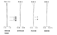
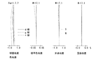
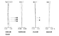
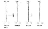
次に具体的な実施例を示す。諸収差図中、球面収差で表される色収差(軸上色収差)図及び倍率色収差図中のd線、g線、c線はそれぞれの波長に対する収差であり、Sはサジタル、Mはメリディオナルである。表中のFNOはFナンバー、fは全系の焦点距離、Wは半画角(゜)、fB はバックフォーカス、rは曲率半径、dはレンズ厚またはレンズ間隔、Nd はd線に対する屈折率、νはアッベ数を示す。
回転対称非球面は次式で定義される。
x=cy2/[1+[1-(1+K)c2y2]1/2]+A4y4+A6y6+A8y8 +A10y10+A12y12・・・
(但し、cは曲率(1/r)、yは光軸からの高さ、Kは円錐係数、A4、A6、A8、・・・・・は各次数の非球面係数)
Next, specific examples will be described. In the various aberration diagrams, the d-line, g-line, and c-line in the chromatic aberration (axial chromatic aberration) diagram and the lateral chromatic aberration diagram represented by spherical aberration are aberrations for the respective wavelengths, S is sagittal, and M is meridional. . F NO is the F-number in the table, f is the focal length of the entire system, W is the half angle (°), f B is the back focus, r is the radius of curvature, d designates the lens-element thickness or distance between lens, N d is the d-line Is the refractive index, and ν is the Abbe number.
A rotationally symmetric aspherical surface is defined by the following equation.
x = cy 2 / [1+ [1- (1 + K) c 2 y 2 ] 1/2 ] + A4y 4 + A6y 6 + A8y 8 + A10y 10 + A12y 12 ...
(Where c is the curvature (1 / r), y is the height from the optical axis, K is the conic coefficient, A4, A6, A8,... Are the aspheric coefficients of each order)
また、非球面係数と収差係数との間には、次の関係がある。
1.非球面形状を次式で定義する。
x=cy2/[1+[1-(1+K)c2y2]1/2]+A4y4+A6y6+A8y8 +A10y10+・・・
(但し、x:非球面形状、c:曲率、y:光軸からの高さ、K:円錐係数)
2.この式において、収差係数を求めるため、K=0 に変換する(K=0 のときは、Bi=Ai)ため、
B4=A4+Kc3/8 ,
B6=A6+(K2+2K)c5/16,
B8=A8+5(K3+3K2+3K)c7/128
B10=A10+7(K4+4K3+6K2+4K)c9/256
とすると、
x=cy2/[1+[1-c2y2]1/2]+B4y4+B6y6+B8y8 +B10y10+・・・
となる。
3.さらに、f=1.0 に変換するため、
X=x/f, Y=y/f, C=f・c,
α4=f3B4, α6=f5B6, α8=f7B8, α10=f9B10
とすると、
X=CY2/[1+[1-C2Y2]1/2]+α4Y4+α6Y6+α8Y8+α10Y10+・・・
となる。
4.Φ=8(N'-N)α4 で定義し、3次の収差係数を、
I : 球面収差係数、
II: コマ収差係数、
III:非点収差係数、
IV: 球欠像面湾曲係数、
V:歪曲収差係数、
とすると、各収差係数の4次の非球面係数(α4)の影響は、
ΔI=h4Φ
ΔII=h3kΦ
ΔIII=h2k2Φ
ΔIV=h2k2 Φ
ΔV=hk3 Φ
(但し、h:近軸軸上光線の通る高さ、k:瞳の中心を通る近軸軸外光線の高さN':非球面の後側の屈折率、N:非球面の前側の屈折率)で与えられる。
In addition, the following relationship exists between the aspheric coefficient and the aberration coefficient.
1. The aspheric shape is defined by the following equation.
x = cy 2 / [1+ [1- (1 + K) c 2 y 2 ] 1/2 ] + A4y 4 + A6y 6 + A8y 8 + A10y 10 + ...
(Where x: aspherical shape, c: curvature, y: height from the optical axis, K: cone coefficient)
2. In this equation, K = 0 is converted to obtain the aberration coefficient (Bi = Ai when K = 0).
B4 = A4 + Kc 3/8 ,
B6 = A6 + (K 2 + 2K)
B8 = A8 + 5 (K 3 +
B10 = A10 + 7 (K 4 + 4K 3 +
Then,
x = cy 2 / [1+ [1-c 2 y 2 ] 1/2 ] + B4y 4 + B6y 6 + B8y 8 + B10y 10 + ...
It becomes.
3. Furthermore, to convert to f = 1.0,
X = x / f, Y = y / f, C = f ・ c,
α4 = f 3 B4, α6 = f 5 B6, α8 = f 7 B8, α10 = f 9 B10
Then,
X = CY 2 / [1+ [1-C 2 Y 2 ] 1/2 ] + α4Y 4 + α6Y 6 + α8Y 8 + α10Y 10 + ...
It becomes.
4). Φ = 8 (N'-N) α4 and the third-order aberration coefficient is
I: spherical aberration coefficient,
II: Comatic aberration coefficient,
III: Astigmatism coefficient,
IV: Tamaketsuzo curvature factor,
V: Distortion coefficient,
Then, the influence of the fourth-order aspheric coefficient (α4) of each aberration coefficient is
ΔI = h 4 Φ
ΔII = h 3 kΦ
ΔIII = h 2 k 2 Φ
ΔIV = h 2 k 2 Φ
ΔV = hk 3 Φ
(However, h: height through which a paraxial ray, k: paraxial light rays passing through the center of the pupil height N ': refractive index of the rear side of the aspherical surface, N: a refractive front aspheric Rate).
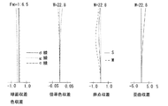
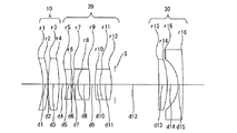
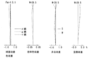
図4ないし図7は本発明のズームレンズ系の第1実施例を示している。この実施例は、図1の移動軌跡を有する3群タイプのテレフォトタイプズームレンズ系に適用したものである。図4はレンズ構成図を示し、図5、図6及び図7はそれぞれ短焦点距離(fw)、中間焦点距離(fm)及び長焦点距離(ft)における諸収差図を示している。表1はその数値データである。FNO、W、fBの値と第4面及び第12面のdの値は、fw‐fm‐ftの順に示している。絞りSは第1レンズ群10(第12面)の後方1.00の位置にある。第1レンズ群10は、物体側から順に、物体側に凹の負メニスカスレンズと、正単レンズからなり、第2レンズ群20は両凹負レンズと、物体側に凸の負メニスカスレンズと正レンズの接合レンズと、物体側に凸の負メニスカスレンズと正レンズの接合レンズからなり、第3レンズ群30は正単レンズと負単レンズからなっている。
4 to 7 show a first embodiment of the zoom lens system of the present invention. This embodiment is applied to a three-group type telephoto type zoom lens system having the movement locus shown in FIG. Figure 4 shows a lens arrangement shown in FIG. 5, shows various aberration diagrams in FIGS. 6 and 7 the short focal length, respectively (fw), the intermediate focal length (fm) and the long focal length (ft). Table 1 shows the numerical data. The values of F NO , W, and f B and the values of d on the fourth surface and the twelfth surface are shown in the order of fw−fm−ft. The stop S is at a position 1.00 behind the first lens group 10 (the twelfth surface). The
(表1)
FNO = 1:5.1 ‐ 6.5 ‐ 13.2
f = 39.00 ‐50.00 ‐136.00
W = 28.4 ‐22.8 ‐ 8.9
fB = 9.98 ‐18.24 ‐ 67.56
面 No. r d Nd ν
1 -24.896 1.50 1.84666 23.8
2 -33.600 0.10 - -
3 42.300 3.40 1.48749 70.2
4 -42.300 1.58-2.40-16.29 - -
5 -22.785 1.50 1.88300 40.8
6 35.571 0.36 - -
7 23.707 1.50 1.83400 37.2
8 14.791 3.12 1.76182 26.5
9 224.000 3.06 - -
10 17.239 1.50 1.84666 23.8
11 11.785 3.84 1.58547 29.9
12* -22.805 15.39-12.34-3.55 - -
13* -76.811 2.60 1.58547 29.9
14 -27.979 3.55 - -
15 -10.447 1.50 1.69680 55.5
16 -365.980 - - -
*は回転対称非球面。
非球面データ(表示していない非球面係数は0.00である。):
面No. K A4 A6 A8
12 0.00 0.67142×10⁻⁴ -0.63070×10⁻⁷ ‐
13 0.00 0.84681×10⁻⁴ -0.23961×10⁻⁶ 0.71242×10⁻⁸
(Table 1)
F NO = 1: 5.1 - 6.5 - 13.2
f = 39.00 -50.00 -136.00
W = 28.4 -22.8 -8.9
f B = 9.98-18.24-67.56
Surface No. r d N d ν
1 -24.896 1.50 1.84666 23.8
2 -33.600 0.10--
3 42.300 3.40 1.48749 70.2
4 -42.300 1.58-2.40-16.29--
5 -22.785 1.50 1.88300 40.8
6 35.571 0.36--
7 23.707 1.50 1.83400 37.2
8 14.791 3.12 1.76182 26.5
9 224.000 3.06--
10 17.239 1.50 1.84666 23.8
11 11.785 3.84 1.58547 29.9
12 * -22.805 15.39-12.34-3.55--
13 * -76.811 2.60 1.58547 29.9
14 -27.979 3.55--
15 -10.447 1.50 1.69680 55.5
16 -365.980---
* Is a rotationally symmetric aspherical surface.
Aspheric data (Aspheric coefficient not shown is 0.00):
Surface No. K A4 A6 A8
12 0.00 0.67142 × 10 -4 -0.63070 × 10 -7 -
13 0.00 0.84681 × 10 -4 -0.23961 × 10 -6 0.71242 × 10 -8
図8ないし図11は本発明のズームレンズ系の第2実施例を示している。この実施例は、実施例1と同じく、図1の移動軌跡を有する3群タイプのテレフォトズームレンズ系に適用したもので、図8はレンズ構成図を示し、図9、図10及び図11はそれぞれ短焦点距離(fw)、中間焦点距離(fm)及び長焦点距離(ft)における諸収差図を示している。表2はその数値データである。FNO、W、fBの値と第4面及び第12面のdの値は、fw‐fm‐ftの順に示している。絞りSは第1レンズ群10(第12面)の後方1.00の位置にある。 8 to 11 show a second embodiment of the zoom lens system of the present invention. This embodiment is applied to the three-group type telephoto zoom lens system having the movement locus shown in FIG. 1, as in the first embodiment. FIG. 8 shows a lens configuration diagram, and FIGS. 9, 10 and 11 are used. Are diagrams showing various aberrations at a short focal length (fw), an intermediate focal length (fm), and a long focal length (ft), respectively. Table 2 shows the numerical data. The values of F NO , W, and f B and the values of d on the fourth surface and the twelfth surface are shown in the order of fw−fm−ft. The stop S is at a position 1.00 behind the first lens group 10 (the twelfth surface).
(表2)
FNO = 1:5.1 ‐ 7.4 ‐ 13.0
f = 39.00 ‐60.00 ‐136.00
W = 28.5 ‐19.4 ‐ 8.9
fB = 10.26 ‐25.03 ‐ 68.08
面 No. r d Nd ν
1 -24.388 1.50 1.84666 23.8
2 -32.252 0.10 - -
3 42.354 3.40 1.48749 70.2
4 -42.354 2.38-5.50-16.72 - -
5 -18.643 1.50 1.88300 40.8
6 48.203 0.20 - -
7 22.643 1.50 1.83400 37.2
8 9.000 3.87 1.68893 31.1
9 -32.623 1.96 - -
10 37.243 1.50 1.84666 23.8
11 15.608 3.47 1.66625 0.0
12* -22.364 14.70-9.90-3.25 - -
13* -58.545 2.60 1.58547 29.9
14 -25.257 3.43 - -
15 -9.989 1.50 1.69680 55.5
16 -160.197 - - -
*は回転対称非球面。
非球面データ(表示していない非球面係数は0.00である。):
面No. K A4 A6 A8
12 0.00 0.76811×10⁻⁵ -0.28541×10⁻⁶ ‐
13 0.00 0.91234×10⁻⁴ -0.12119×10⁻⁶ 0.80186×10⁻⁸
(Table 2)
F NO = 1: 5.1-7.4-13.0
f = 39.00 ‐60.00 ‐136.00
W = 28.5-19.4-8.9
f B = 10.26-25.03-68.08
Surface No. r d N d ν
1 -24.388 1.50 1.84666 23.8
2 -32.252 0.10--
3 42.354 3.40 1.48749 70.2
4 -42.354 2.38-5.50-16.72--
5 -18.643 1.50 1.88300 40.8
6 48.203 0.20--
7 22.643 1.50 1.83400 37.2
8 9.000 3.87 1.68893 31.1
9 -32.623 1.96--
10 37.243 1.50 1.84666 23.8
11 15.608 3.47 1.66625 0.0
12 * -22.364 14.70-9.90-3.25--
13 * -58.545 2.60 1.58547 29.9
14 -25.257 3.43--
15 -9.989 1.50 1.69680 55.5
16 -160.197---
* Is a rotationally symmetric aspherical surface.
Aspheric data (Aspheric coefficient not shown is 0.00):
Surface No. K A4 A6 A8
12 0.00 0.76811 × 10 -5 -0.28541 × 10 -6 -
13 0.00 0.91234 × 10 -4 -0.12119 × 10 -6 0.80186 × 10 -8
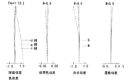
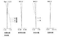
図12ないし図15は本発明のズームレンズ系の第3実施例を示している。この実施例は、実施例1及び2と同じく、図1の移動軌跡を有する3群タイプのテレフォトズームレンズ系に適用したもので、図12はレンズ構成図を示し、図13、図14及び図15はそれぞれ短焦点距離(fw)、中間焦点距離(fm)及び長焦点距離(ft)における諸収差図を示している。表3はその数値データである。FNO、W、fBの値と第4面及び第12面のdの値は、fw‐fm‐ftの順に示している。絞りSは第1レンズ群10(第12面)の後方1.00の位置にある。 12 to 15 show a third embodiment of the zoom lens system of the present invention. This embodiment is applied to the three-group type telephoto zoom lens system having the movement locus shown in FIG. 1 as in the first and second embodiments. FIG. 12 shows a lens configuration diagram, and FIGS. FIG. 15 shows various aberration diagrams at a short focal length (fw), an intermediate focal length (fm), and a long focal length (ft), respectively. Table 3 shows the numerical data. The values of F NO , W, and f B and the values of d on the fourth surface and the twelfth surface are shown in the order of fw−fm−ft. The stop S is at a position 1.00 behind the first lens group 10 (the twelfth surface).
(表3)
FNO = 1:5.1 ‐ 8.5 ‐ 13.0
f = 39.00 ‐70.00 ‐136.00
W = 28.5 ‐16.9 ‐ 8.9
fB = 10.24 ‐32.26 ‐ 68.14
面 No. r d Nd ν
1 -24.470 1.50 1.84666 23.8
2 -32.300 0.10 - -
3 42.600 3.40 1.48749 70.2
4 -42.600 2.34-6.00-16.71 - -
5 -19.380 1.50 1.88300 40.8
6 66.339 0.53 - -
7 24.330 1.50 1.83400 37.2
8 9.000 3.75 1.69865 30.1
9 -50.460 1.63 - -
10 34.600 1.54 1.84666 23.8
11 14.677 3.55 1.66625 0.0
12* -21.443 14.74-8.59-3.26 - -
13* -60.407 2.60 1.58547 29.9
14 -25.594 3.41 - -
15 -10.014 1.50 1.69680 55.5
16 -161.880 - - -
*は回転対称非球面。
非球面データ(表示していない非球面係数は0.00である。):
面No. K A4 A6 A8
12 0.00 0.12240×10⁻⁴ -0.26469×10⁻⁶ ‐
13 0.00 0.91483×10⁻⁴ -0.11147×10⁻⁶ 0.78421×10⁻⁸
(Table 3)
F NO = 1: 5.1-8.5-13.0
f = 39.00 -70.00 -136.00
W = 28.5-16.9-8.9
f B = 10.24 -32.26-68.14
Surface No. r d N d ν
1 -24.470 1.50 1.84666 23.8
2 -32.300 0.10--
3 42.600 3.40 1.48749 70.2
4 -42.600 2.34-6.00-16.71--
5 -19.380 1.50 1.88300 40.8
6 66.339 0.53--
7 24.330 1.50 1.83400 37.2
8 9.000 3.75 1.69865 30.1
9 -50.460 1.63--
10 34.600 1.54 1.84666 23.8
11 14.677 3.55 1.66625 0.0
12 * -21.443 14.74-8.59-3.26--
13 * -60.407 2.60 1.58547 29.9
14 -25.594 3.41--
15 -10.014 1.50 1.69680 55.5
16 -161.880---
* Is a rotationally symmetric aspherical surface.
Aspheric data (Aspheric coefficient not shown is 0.00):
Surface No. K A4 A6 A8
12 0.00 0.12240 × 10 -4 -0.26469 × 10 -6 -
13 0.00 0.91483 × 10 -4 -0.11147 × 10 -6 0.78421 × 10 -8
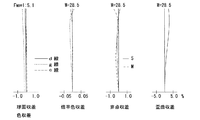
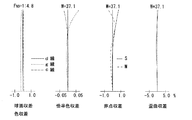
図16ないし図19は本発明のズームレンズ系の第4実施例を示している。この実施例は、図2の移動軌跡を有する4群タイプのテレフォトズームレンズ系に適用したもので、図16はレンズ構成図を示し、図17、図18及び図19はそれぞれ短焦点距離端(fw)、中間焦点距離(fm)及び長焦点距離端(ft)における諸収差図を示している。表4はその数値データである。FNO、W、fBの値と第4面、第7面及び第12面のdの値は、fw‐fm‐ftの順に示している。絞りSは第3レンズ群60(第12面)の後方0.70の位置にある。第1レンズ群40は、物体側から順に、物体側に凹の負メニスカスレンズと正単レンズからなり、第2レンズ群50は両凹負レンズと正レンズの接合レンズからなり、第3レンズ群60は、物体側から順に、物体側に凸の負メニスカスレンズと正レンズの接合レンズと正単レンズからなり、第4レンズ群は、物体側から順に、正単レンズと負単レンズとからなっている。
FIGS. 16 to 19 show a fourth embodiment of the zoom lens system of the present invention. This embodiment is obtained by applying to the telephoto zoom lens system of the four-group type having a moving locus of Figure 2, Figure 16 shows the lens arrangement shown in FIGS. 17, 18 and 19 the short focal length end, respectively The aberration diagrams at (fw), the intermediate focal length (fm), and the long focal length end (ft) are shown. Table 4 shows the numerical data. The values of F NO , W, and f B and the values of d on the fourth surface, the seventh surface, and the twelfth surface are shown in the order of fw−fm−ft. The stop S is at a position 0.70 behind the third lens group 60 (the twelfth surface). The
(表4)
FNO = 1:4.8 ‐ 7.7 ‐ 12.0
f = 28.50 ‐70.00 ‐138.00
W = 37.1 ‐17.2 ‐ 8.8
fB = 8.00 ‐38.95 ‐ 65.00
面 No. r d Nd ν
1 -28.382 1.00 1.84666 23.8
2 -51.190 0.10 - -
3 34.000 3.00 1.60311 60.7
4 -50.661 1.80-9.02-14.70 - -
5* -16.815 1.00 1.77250 49.6
6 10.426 2.86 1.80518 25.4
7 28.589 3.10-2.80-0.30 - -
8 10.888 1.00 1.80518 25.4
9 7.502 3.70 1.58913 61.2
10* -108.815 0.20 - -
11 43.460 2.40 1.51633 64.1
12 -21.272 11.63-3.57-3.48 - -
13* -113.135 2.80 1.58547 29.9
14* -23.031 3.16 - -
15 -9.678 1.30 1.72916 54.7
16 768.406 - - -
*は回転対称非球面。
非球面データ(表示していない非球面係数は0.00である。):
面No. K A4 A6 A8
5 0.00 0.33220×10⁻⁴ 0.39879×10⁻⁶ -0.35918×10⁻⁸
10 0.00 0.16388×10⁻³ 0.10725×10⁻⁵ -0.10973×10⁻⁷
13 0.00 0.57420×10⁻⁴ 0.61735×10⁻⁶ 0.10702×10⁻⁷
14 0.00 -0.46592×10⁻⁴ 0.10334×10⁻⁵ 0.60275×10⁻⁸
(Table 4)
F NO = 1: 4.8-7.7-12.0
f = 28.50 -70.00 -138.00
W = 37.1-17.2-8.8
f B = 8.00 ‐38.95 ‐ 65.00
Surface No. r d N d ν
1 -28.382 1.00 1.84666 23.8
2 -51.190 0.10--
3 34.000 3.00 1.60311 60.7
4 -50.661 1.80-9.02-14.70--
5 * -16.815 1.00 1.77250 49.6
6 10.426 2.86 1.80518 25.4
7 28.589 3.10-2.80-0.30--
8 10.888 1.00 1.80518 25.4
9 7.502 3.70 1.58913 61.2
10 * -108.815 0.20--
11 43.460 2.40 1.51633 64.1
12 -21.272 11.63-3.57-3.48--
13 * -113.135 2.80 1.58547 29.9
14 * -23.031 3.16--
15 -9.678 1.30 1.72916 54.7
16 768.406---
* Is a rotationally symmetric aspherical surface.
Aspheric data (Aspheric coefficient not shown is 0.00):
Surface No. K A4 A6 A8
5 0.00 0.33220 × 10 -4 0.39879 × 10 -6 -0.35918 × 10 -8
10 0.00 0.16388 × 10 -3 0.10725 × 10 -5 -0.10973 × 10 -7
13 0.00 0.57420 × 10 -4 0.61735 × 10 -6 0.10702 × 10 -7
14 0.00 -0.46592 × 10 -4 0.10334 × 10 -5 0.60275 × 10 -8
図20ないし図23は本発明のズームレンズ系の第4実施例を示している。この実施例は、第4実施例と同じく、図2の移動軌跡を有する4群タイプのテレフォトズームレンズ系に適用したもので、図20はレンズ構成図を示し、図21、図22及び図23はそれぞれ短焦点距離(fw)、中間焦点距離(fm)及び長焦点距離(ft)における諸収差図を示している。表5はその数値データである。FNO、W、fBの値と第4面、第7面及び第12面のdの値は、fw‐fm‐ftの順に示している。絞りSは第3レンズ群60(第12面)の後方0.70の位置にある 20 to 23 show a fourth embodiment of the zoom lens system of the present invention. Like the fourth embodiment, this embodiment is applied to a four-group type telephoto zoom lens system having the movement locus shown in FIG. 2, and FIG. 20 shows a lens configuration diagram, and FIGS. 21, 22, and FIG. 23 shows various aberration diagrams at a short focal length (fw), an intermediate focal length (fm), and a long focal length (ft), respectively. Table 5 shows the numerical data. The values of F NO , W, and f B and the values of d on the fourth surface, the seventh surface, and the twelfth surface are shown in the order of fw−fm−ft. The stop S is at a position 0.70 behind the third lens group 60 (the twelfth surface).
(表5)
FNO = 1:5.3 ‐ 7.7 ‐ 12.0
f = 28.50 ‐70.00 ‐138.00
W = 36.6 ‐17.1 ‐ 8.7
fB = 8.30 ‐39.74 ‐ 65.85
面 No. r d Nd ν
1 -32.696 1.10 1.84666 23.8
2 -56.953 0.10 - -
3 36.288 2.90 1.58913 61.2
4 -57.074 1.80-9.99-15.80 - -
5* -16.922 1.00 1.80400 46.6
6 10.343 2.98 1.78472 25.7
7 40.454 3.30-3.00-0.30 - -
8 10.875 1.00 1.84666 23.8
9 7.647 3.70 1.58913 61.2
10* -101.328 0.20 - -
11 51.984 2.36 1.51633 64.1
12 -21.403 11.75-3.44-3.48 - -
13* -96.239 2.71 1.60585 27.0
14* -22.327 3.22 - -
15 -9.690 1.30 1.72916 54.7
16 8650.450 - - -
*は回転対称非球面。
非球面データ(表示していない非球面係数は0.00である。):
面No. K A4 A6 A8
5 0.00 0.33464×10⁻⁴ 0.42469×10⁻⁶ -0.50410×10⁻⁸
10 0.00 0.15477×10⁻³ 0.98126×10⁻⁶ -0.10973×10⁻⁷
13 0.00 0.62569×10⁻⁴ 0.97610×10⁻⁶ 0.81060×10⁻⁸
14 0.00 -0.19172×10⁻⁴ 0.12386×10⁻⁵ 0.60275×10⁻⁸
(Table 5)
F NO = 1: 5.3-7.7-12.0
f = 28.50 -70.00 -138.00
W = 36.6 ‐17.1 ‐ 8.7
f B = 8.30 -39.74-65.85
Surface No. r d N d ν
1 -32.696 1.10 1.84666 23.8
2 -56.953 0.10--
3 36.288 2.90 1.58913 61.2
4 -57.074 1.80-9.99-15.80--
5 * -16.922 1.00 1.80 400 46.6
6 10.343 2.98 1.78472 25.7
7 40.454 3.30-3.00-0.30--
8 10.875 1.00 1.84666 23.8
9 7.647 3.70 1.58913 61.2
10 * -101.328 0.20 - -
11 51.984 2.36 1.51633 64.1
12 -21.403 11.75-3.44-3.48--
13 * -96.239 2.71 1.60585 27.0
14 * -22.327 3.22--
15 -9.690 1.30 1.72916 54.7
16 8650.450---
* Is a rotationally symmetric aspherical surface.
Aspheric data (Aspheric coefficient not shown is 0.00):
Surface No. K A4 A6 A8
5 0.00 0.33464 × 10 -4 0.42469 × 10 -6 -0.50410 × 10 -8
10 0.00 0.15477 × 10 -3 0.98 126 × 10 -6 -0.10973 × 10 -7
13 0.00 0.62569 × 10 -4 0.97610 × 10 -6 0.81060 × 10 -8
14 0.00 -0.19172 × 10 -4 0.12386 × 10 -5 0.60275 × 10 -8
図24ないし図28は本発明のズームレンズ系の第6実施例を示している。この実施例は、図3に移動軌跡を有する4群タイプのテレフォトズームレンズ系に適用したもので、図24はレンズ構成図を示し、図25、図26、図27及び図28はそれぞれ短焦点距離(fw)、焦点距離域ZW中における焦点距離(fm1)、切替後、焦点距離域ZT中における焦点距離(fm2)及び長焦点距離(ft)における諸収差図を示している。表6はその数値データである。FNO、W、fBの値と第4面、第7面及び第12面のdの値は、fw‐fm1‐fm2−ftの順に示している。第2レンズ群90と第3レンズ群100は、焦点距離域ZWでは第一の間隔d1(=3.60)を維持し、焦点距離域ZTでは第二の間隔d2(=0.30)を維持する。絞りSは第3レンズ群60(第12面)の後方0.70の位置にある。第1レンズ群40は、物体側から順に、物体側に凹の負メニスカスレンズと正単レンズからなり、第2レンズ群50は両凹負レンズと正レンズの接合レンズからなり、第3レンズ群60は、物体側から順に、物体側に凸の負メニスカスレンズと正レンズの接合レンズと正単レンズからなり、第4レンズ群は、物体側から順に、正単レンズと負単レンズとからなっている。
24 to 28 show a sixth embodiment of the zoom lens system of the present invention. This embodiment is applied to a four-group type telephoto zoom lens system having the movement locus shown in FIG. 3. FIG. 24 shows a lens configuration diagram, and FIGS. 25, 26, 27 and 28 are short diagrams. The graphs of various aberrations in the focal length (fw), the focal length (fm1) in the focal length range ZW, the focal length (fm2) in the focal length range ZT and the long focal length (ft) after switching are shown. Table 6 shows the numerical data. The values of F NO , W, and f B and the values of d on the fourth surface, the seventh surface, and the twelfth surface are shown in the order of fw−fm1−fm2−ft. The
(表6)
FNO = 1:5.3 ‐ 9.6 ‐ 9.8 - 12.5
f = 28.50 ‐70.00 ‐ 90.00 - 138.00
W = 36.5 ‐17.2 ‐ 12.9 - 8.7
fB = 8.30 ‐43.01 ‐ 37.46 - 67.82
面 No. r d Nd ν
1 -32.378 1.20 1.84666 23.8
2 -58.898 0.10 - -
3 40.369 2.80 1.61800 63.4
4 -53.821 1.88-9.44-15.10-15.59 - -
5* -17.750 1.20 1.80400 46.6
6 10.593 2.99 1.78472 25.7
7 42.692 3.60-3.60-0.30-0.30 - -
8 10.938 1.20 1.84666 23.8
9 7.588 3.80 1.60970 57.8
10* -246.158 0.20 - -
11 55.976 2.27 1.51633 64.1
12 -22.315 12.06-2.85-6.21-3.48 - -
13* -72.551 2.60 1.68893 31.1
14* -21.066 3.05 - -
15 -9.828 1.40 1.72916 54.7
16 477.075 - - -
*は回転対称非球面。
非球面データ(表示していない非球面係数は0.00である。):
面No. K A4 A6 A8
5 0.00 0.30189×10⁻⁴ 0.36711×10⁻⁶ -0.42456×10⁻⁸
10 0.00 0.15502×10⁻³ 0.10025×10⁻⁵ -0.10973×10⁻⁷
13 0.00 0.51569×10⁻⁴ 0.94227×10⁻⁶ 0.76974×10⁻⁸
14 0.00 -0.19688×10⁻⁴ 0.11413×10⁻⁵ 0.60275×10⁻⁸
(Table 6)
F NO = 1: 5.3-9.6-9.8-12.5
f = 28.50 -70.00 -90.00-138.00
W = 36.5 -17.2 -12.9-8.7
f B = 8.30 ‐43.01 ‐ 37.46-67.82
Surface No. r d N d ν
1 -32.378 1.20 1.84666 23.8
2 -58.898 0.10--
3 40.369 2.80 1.61800 63.4
4 -53.821 1.88-9.44-15.10-15.59--
5 * -17.750 1.20 1.80 400 46.6
6 10.593 2.99 1.78472 25.7
7 42.692 3.60-3.60-0.30-0.30--
8 10.938 1.20 1.84666 23.8
9 7.588 3.80 1.60970 57.8
10 * -246.158 0.20 - -
11 55.976 2.27 1.51633 64.1
12 -22.315 12.06-2.85-6.21-3.48--
13 * -72.551 2.60 1.68893 31.1
14 * -21.066 3.05--
15 -9.828 1.40 1.72916 54.7
16 477.075---
* Is a rotationally symmetric aspherical surface.
Aspheric data (Aspheric coefficient not shown is 0.00):
Surface No. K A4 A6 A8
5 0.00 0.30189 × 10 -4 0.36711 × 10 -6 -0.42456 × 10 -8
10 0.00 0.15502 × 10 -3 0.10025 × 10 -5 -0.10973 × 10 -7
13 0.00 0.51569 × 10 -4 0.94227 × 10 -6 0.76974 × 10 -8
14 0.00 -0.19688 × 10 -4 0.11413 × 10 -5 0.60275 × 10 -8
各実施例の各条件式に対する値を表7に示す。
(表7)
実施例1 実施例2 実施例3 実施例4 実施例5 実施例6
条件式(1) 1.28 1.54 1.79 1.85 1.75 1.82
条件式(2) 0.64 0.48 0.71 0.52 0.67 0.74
条件式(3) 2.88 2.89 2.90 1.94 2.73 1.82
条件式(4) 0.83 0.83 0.83 0.40 0.56 0.38
条件式(5) 3.49 3.49 3.49 4.84 4.84 4.84
条件式(6) - - - 1.85 1.75 1.82
条件式(7) - - - 0.40 0.56 0.38
条件式(8) - - - 0.58 0.62 0.68
条件式(9) - - - -10.15 -9.79 -9.32
条件式(10) - - - 1.14 1.16 1.15
条件式(11) - - - 4.84 4.84 4.84
条件式(12) - - - 4.34 4.54 4.17
条件式(13) - - - -34.43 -34.19 -34.38
条件式(14) 0.51 0.50 0.50 0.31 0.24 0.26
Table 7 shows values for each conditional expression in each example.
(Table 7)
Example 1 Example 2 Example 3 Example 4 Example 5 Example 6
Conditional expression (1) 1.28 1.54 1.79 1.85 1.75 1.82
Conditional expression (2) 0.64 0.48 0.71 0.52 0.67 0.74
Conditional expression (3) 2.88 2.89 2.90 1.94 2.73 1.82
Conditional expression (4) 0.83 0.83 0.83 0.40 0.56 0.38
Conditional expression (5) 3.49 3.49 3.49 4.84 4.84 4.84
Conditional expression (6)---1.85 1.75 1.82
Conditional expression (7)---0.40 0.56 0.38
Conditional expression (8)---0.58 0.62 0.68
Conditional expression (9)----10.15 -9.79 -9.32
Conditional expression (10)---1.14 1.16 1.15
Conditional expression (11)---4.84 4.84 4.84
Conditional expression (12)---4.34 4.54 4.17
Conditional expression (13)----34.43 -34.19 -34.38
Conditional expression (14) 0.51 0.50 0.50 0.31 0.24 0.26
表7からも明らかなように、実施例1ないし実施例6の数値は、条件式(1)ないし(14)を満足しており、かつ収差図に示すように各焦点距離での諸収差もよく補正されている。 As is apparent from Table 7, the numerical values of Examples 1 to 6 satisfy the conditional expressions (1) to (14), and various aberrations at each focal length are also shown in the aberration diagrams. well it has been corrected.
10 40 80 第1レンズ群
20 50 90 第2レンズ群
30 60 100 第3レンズ群
110 第4レンズ群
S 絞り
10 40 80
Claims (17)
第1レンズ群の最も物体側の面から最終レンズ群の最も像側の面迄の距離が、最短焦点距離と最長焦点距離の間の中間焦点距離において最短となることを特徴とするズームレンズ系。 Comprising a lens group of n to move during zooming (n ≧ 3), a first lens group of the most object side positive refractive power, zooming last lens group closest to the image side has a negative refractive power in the lens system,
A zoom lens system characterized in that the distance from the most object side surface of the first lens group to the most image side surface of the last lens group is the shortest at an intermediate focal length between the shortest focal length and the longest focal length. .
(1)1.0<fM/fW<3.0
但し、
fM:第1レンズ群の最も物体側の面から最終レンズ群の最も像側の面迄の距離が最小となる中間焦点距離、
fW:全系の短焦点距離端における焦点距離。 The zoom lens system according to claim 1, wherein the zoom lens system satisfies the following conditional expression (1).
(1) 1.0 <f M / f W <3.0
However,
f M : an intermediate focal length at which the distance from the most object-side surface of the first lens unit to the most image-side surface of the final lens unit is minimized;
f W : focal length at the short focal length end of the entire system.
(2)0.3<(LDW−LDM)/(fT/fW)<1.0
但し、
LDW:短焦点距離端における第1レンズ群の最も物体側の面から最終レンズ群の最も像側の面迄の距離
LDM:中間焦点距離fMにおける第1レンズ群の最も物体側の面から最終レンズ群の最も像側の面迄の距離
fT:全系の長焦点距離端における焦点距離。 The zoom lens system according to claim 1 or 2, wherein the zoom lens system satisfies the following conditional expression (2).
(2) 0.3 <(LD W −LD M ) / (f T / f W ) <1.0
However,
LD W: the most distance to the surface on the image side LD M final lens group from the most object side surface of the first lens group at the short focal length end: a most object side surface of the first lens group in the intermediate focal length f M To the most image side surface of the last lens group f T : focal length at the long focal length end of the entire system.
(3)0<LDT−LDW
但し、
LDT:長焦点距離端における第1レンズ群の最も物体側の面から最終レンズ群の最も像側の面迄の距離。 The zoom lens system according to any one of claims 1 to 3, wherein the zoom lens system satisfies the following conditional expression (3).
(3) 0 <LD T −LD W
However,
LD T : Distance from the most object side surface of the first lens unit to the most image side surface of the last lens unit at the long focal length end.
(4)0.3<(LDT−LDW)/(fT/fW)<0.9 The zoom lens system according to any one of claims 1 to 4, wherein the zoom lens system satisfies the following conditional expression (4).
(4) 0.3 <(LD T −LD W ) / (f T / f W ) <0.9
(5)3<fT/fW The zoom lens system according to any one of claims 1 to 5, wherein the zoom lens system satisfies the following conditional expression (5).
(5) 3 <f T / f W
(6)1.2<fM/fW<3.0 9. The zoom lens system according to claim 8, wherein the zoom lens system satisfies the following conditional expression (6).
(6) 1.2 <f M / f W <3.0
(7)0.3<(LDT−LDW)/(fT/fW)<0.7 The zoom lens system according to claim 8 or 9, wherein the zoom lens system satisfies the following conditional expression (7).
(7) 0.3 <(LD T −LD W ) / (f T / f W ) <0.7
(8)0.3<(d23W−d23T)/(fT/fW)<1.5
但し、
d23W:短焦点距離端での第2レンズ群と第3レンズ群の軸上空気間隔、
d23T:長焦点距離端での第2レンズ群と第3レンズ群の軸上空気間隔。 11. The zoom lens system according to claim 8, wherein the zoom lens system satisfies the following conditional expression (8).
(8) 0.3 <(d 23W −d 23T ) / (f T / f W ) <1.5
However,
d23W : axial air space between the second lens unit and the third lens unit at the short focal length end,
d 23T : On-axis air space between the second lens group and the third lens group at the long focal length end.
(9)−12<fT/f2G<−9
但し、
f2G:第2レンズ群の焦点距離。 The zoom lens system according to any one of claims 8 to 11, wherein the zoom lens system satisfies the following conditional expression (9).
(9) -12 <f T / f 2G <-9
However,
f 2G : Focal length of the second lens group.
(10)1.05<h3G/h1<1.30
但し、
h3G:第3レンズ群の最終面に入射する近軸光線の高さh、
h1:第1レンズ群の第1面に入射する近軸光線の高さh。 The zoom lens system according to any one of claims 8 to 12, wherein the zoom lens system satisfies the following conditional expression (10).
(10) 1.05 <h 3G / h 1 <1.30
However,
h 3G : the height h of the paraxial ray incident on the final surface of the third lens group,
h 1 : The height h of the paraxial ray incident on the first surface of the first lens group.
(11)4.5<fT/fW 14. The zoom lens system according to claim 8, further comprising a lens that satisfies the following conditional expression (11).
(11) 4.5 <f T / f W
(12)3<ΔI(2G)asp<9
但し、
ΔI(2G)asp:短焦点距離端の焦点距離を1.0に換算したときの非球面による球面収差係数の変化量。 The zoom lens system according to any one of claims 8 to 14, wherein the second lens group includes a lens having at least one aspherical surface that satisfies the following conditional expression (12).
(12) 3 <ΔI (2G) asp <9
However,
ΔI (2G) asp: The amount of change in the spherical aberration coefficient due to the aspherical surface when the focal length at the short focal length end is converted to 1.0.
(13)−40<ΔI(3G)asp<−10
但し、
ΔI(3G)asp:短焦点距離端の焦点距離を1.0に換算したときの非球面による球面収差係数の変化量。 16. The zoom lens system according to claim 8, wherein the third lens group includes a lens having at least one aspherical surface that satisfies the following conditional expression (13).
(13) −40 <ΔI (3G) asp <−10
However,
ΔI (3G) asp: The amount of change in spherical aberration coefficient due to the aspherical surface when the focal length at the short focal length end is converted to 1.0.
(14)0<ΔVasp<3
但し、
ΔVasp:短焦点距離端の焦点距離を1.0に換算したときの非球面による球面収差係数の変化量。 17. The zoom lens system according to claim 1, wherein the final lens group having negative refractive power includes a lens having at least one aspherical surface that satisfies the following conditional expression (14). .
(14) 0 <ΔVasp <3
However,
ΔVasp: A change amount of the spherical aberration coefficient due to the aspherical surface when the focal length at the short focal length end is converted to 1.0.
Priority Applications (2)
| Application Number | Priority Date | Filing Date | Title |
|---|---|---|---|
| JP2004079042A JP2005266344A (en) | 2004-03-18 | 2004-03-18 | Zoom lens system |
| US11/081,497 US7164540B2 (en) | 2004-03-18 | 2005-03-17 | Zoom lens system |
Applications Claiming Priority (1)
| Application Number | Priority Date | Filing Date | Title |
|---|---|---|---|
| JP2004079042A JP2005266344A (en) | 2004-03-18 | 2004-03-18 | Zoom lens system |
Publications (2)
| Publication Number | Publication Date |
|---|---|
| JP2005266344A true JP2005266344A (en) | 2005-09-29 |
| JP2005266344A5 JP2005266344A5 (en) | 2007-04-19 |
Family
ID=34985969
Family Applications (1)
| Application Number | Title | Priority Date | Filing Date |
|---|---|---|---|
| JP2004079042A Withdrawn JP2005266344A (en) | 2004-03-18 | 2004-03-18 | Zoom lens system |
Country Status (2)
| Country | Link |
|---|---|
| US (1) | US7164540B2 (en) |
| JP (1) | JP2005266344A (en) |
Cited By (1)
| Publication number | Priority date | Publication date | Assignee | Title |
|---|---|---|---|---|
| JP2011232624A (en) * | 2010-04-28 | 2011-11-17 | Olympus Imaging Corp | Imaging device |
Families Citing this family (1)
| Publication number | Priority date | Publication date | Assignee | Title |
|---|---|---|---|---|
| CN114397747A (en) * | 2022-01-27 | 2022-04-26 | 玉晶光电(厦门)有限公司 | Optical imaging lens |
Citations (5)
| Publication number | Priority date | Publication date | Assignee | Title |
|---|---|---|---|---|
| JP2000305019A (en) * | 1999-04-20 | 2000-11-02 | Nikon Corp | Variable focal distance lens system |
| JP2001004921A (en) * | 1999-04-23 | 2001-01-12 | Nikon Corp | Variable focal distance lens system |
| JP2001330778A (en) * | 2000-03-13 | 2001-11-30 | Nikon Corp | Variable focal distance lens system |
| JP2002228928A (en) * | 2001-01-31 | 2002-08-14 | Nikon Corp | Variable focal distance lens system |
| JP2002365553A (en) * | 2001-06-11 | 2002-12-18 | Canon Inc | Zoom lens and optical equipment having the same |
Family Cites Families (12)
| Publication number | Priority date | Publication date | Assignee | Title |
|---|---|---|---|---|
| JP3380009B2 (en) | 1992-10-15 | 2003-02-24 | ペンタックス株式会社 | Zoom lens system |
| US5793533A (en) | 1992-10-15 | 1998-08-11 | Asahi Kogaku Kogyo Kabushiki Kaisha | Zoom lens system |
| JP3328001B2 (en) * | 1993-06-15 | 2002-09-24 | オリンパス光学工業株式会社 | Zoom lens |
| JP3294911B2 (en) | 1993-07-27 | 2002-06-24 | 旭光学工業株式会社 | Zoom lens system |
| JP3836525B2 (en) | 1995-10-25 | 2006-10-25 | ペンタックス株式会社 | High zoom ratio zoom lens |
| JPH10268191A (en) | 1997-03-21 | 1998-10-09 | Asahi Optical Co Ltd | Zoom lens system |
| JP3752097B2 (en) | 1999-03-24 | 2006-03-08 | ペンタックス株式会社 | Zoom lens system |
| KR100472748B1 (en) | 2000-01-28 | 2005-03-07 | 펜탁스 가부시키가이샤 | A zoom lens system |
| JP2004020898A (en) | 2002-06-17 | 2004-01-22 | Pentax Corp | Zoom lens system |
| JP2004184525A (en) | 2002-11-29 | 2004-07-02 | Pentax Corp | Zoom lens system |
| JP2004184526A (en) | 2002-11-29 | 2004-07-02 | Pentax Corp | Zoom lens system |
| JP2005128191A (en) | 2003-10-23 | 2005-05-19 | Pentax Corp | Zoom lens system |
-
2004
- 2004-03-18 JP JP2004079042A patent/JP2005266344A/en not_active Withdrawn
-
2005
- 2005-03-17 US US11/081,497 patent/US7164540B2/en not_active Expired - Fee Related
Patent Citations (5)
| Publication number | Priority date | Publication date | Assignee | Title |
|---|---|---|---|---|
| JP2000305019A (en) * | 1999-04-20 | 2000-11-02 | Nikon Corp | Variable focal distance lens system |
| JP2001004921A (en) * | 1999-04-23 | 2001-01-12 | Nikon Corp | Variable focal distance lens system |
| JP2001330778A (en) * | 2000-03-13 | 2001-11-30 | Nikon Corp | Variable focal distance lens system |
| JP2002228928A (en) * | 2001-01-31 | 2002-08-14 | Nikon Corp | Variable focal distance lens system |
| JP2002365553A (en) * | 2001-06-11 | 2002-12-18 | Canon Inc | Zoom lens and optical equipment having the same |
Cited By (1)
| Publication number | Priority date | Publication date | Assignee | Title |
|---|---|---|---|---|
| JP2011232624A (en) * | 2010-04-28 | 2011-11-17 | Olympus Imaging Corp | Imaging device |
Also Published As
| Publication number | Publication date |
|---|---|
| US20050207025A1 (en) | 2005-09-22 |
| US7164540B2 (en) | 2007-01-16 |
Similar Documents
| Publication | Publication Date | Title |
|---|---|---|
| JP2816436B2 (en) | High-magnification large-aperture zoom optical system | |
| JP3155884B2 (en) | Zoom lens | |
| US10095012B2 (en) | Zoom lens system, optical apparatus and method for manufacturing zoom lens system | |
| JP2008089991A (en) | Zoom lens and imaging apparatus | |
| JP4356040B2 (en) | Long zoom lens with anti-vibration function | |
| JP2008145967A (en) | Zoom lens and imaging apparatus | |
| JP2011248049A (en) | Zoom lens system | |
| JP2003140041A (en) | Zoom lens system | |
| JP2009037125A (en) | Three-group zoom lens system and image pickup apparatus using the same | |
| JP2009282465A (en) | Zoom lens and imaging apparatus | |
| JP2003177314A (en) | Zoom lens | |
| JP2000137163A (en) | Zoom lens system | |
| JP2000193885A (en) | Zoom lens system | |
| JP2003057546A (en) | Zoom lens system | |
| JP4115746B2 (en) | Telephoto zoom lens | |
| JP6268792B2 (en) | Zoom lens, optical device, and zoom lens manufacturing method | |
| JP2000275525A (en) | Variable focal length lens system | |
| JP2015203736A (en) | Super wide angle zoom lens | |
| JPH1090600A (en) | Variable magnification optical system | |
| JP2003075721A (en) | Zoom lens system | |
| JP4890006B2 (en) | Zoom lens | |
| JPH11305129A (en) | Rear focus type zoom lens | |
| JP5987543B2 (en) | Zoom lens, optical device | |
| JPH11211984A (en) | Miniaturized zoom lens | |
| JP2005266344A (en) | Zoom lens system |
Legal Events
| Date | Code | Title | Description |
|---|---|---|---|
| A521 | Written amendment |
Free format text: JAPANESE INTERMEDIATE CODE: A523 Effective date: 20070307 |
|
| A621 | Written request for application examination |
Free format text: JAPANESE INTERMEDIATE CODE: A621 Effective date: 20070307 |
|
| RD04 | Notification of resignation of power of attorney |
Free format text: JAPANESE INTERMEDIATE CODE: A7424 Effective date: 20070621 |
|
| A711 | Notification of change in applicant |
Free format text: JAPANESE INTERMEDIATE CODE: A712 Effective date: 20080501 |
|
| A977 | Report on retrieval |
Free format text: JAPANESE INTERMEDIATE CODE: A971007 Effective date: 20100421 |
|
| A131 | Notification of reasons for refusal |
Free format text: JAPANESE INTERMEDIATE CODE: A131 Effective date: 20100427 |
|
| A761 | Written withdrawal of application |
Free format text: JAPANESE INTERMEDIATE CODE: A761 Effective date: 20100528 |