JP2005264802A - Vane rotary vacuum pump - Google Patents
Vane rotary vacuum pump Download PDFInfo
- Publication number
- JP2005264802A JP2005264802A JP2004077463A JP2004077463A JP2005264802A JP 2005264802 A JP2005264802 A JP 2005264802A JP 2004077463 A JP2004077463 A JP 2004077463A JP 2004077463 A JP2004077463 A JP 2004077463A JP 2005264802 A JP2005264802 A JP 2005264802A
- Authority
- JP
- Japan
- Prior art keywords
- motor case
- motor
- pump
- stator
- ring
- Prior art date
- Legal status (The legal status is an assumption and is not a legal conclusion. Google has not performed a legal analysis and makes no representation as to the accuracy of the status listed.)
- Pending
Links
Images


Abstract
Description
本発明は真空ポンプに関し、特に圧縮機構部およびそれを駆動するモータとを一体に構成した真空ポンプに関するものである。 The present invention relates to a vacuum pump, and more particularly to a vacuum pump in which a compression mechanism and a motor for driving the compression mechanism are integrally formed.
従来、この種のポンプや圧縮機は、電動機の固定子を圧縮機の容器や電動機のケーシングの内周に焼き嵌めしたり、嵌め付けて溶接したり、あるいはボルト止めしたりして固定している。これによって、容器やケーシング内に支持される回転子と所定のエアギャップを保って、効率よく安定して動作させるようにしている(例えば、特許文献1参照)。 Conventionally, this type of pump or compressor is fixed by shrinking the stator of the electric motor to the inner periphery of the compressor container or the casing of the electric motor, fitting and welding, or bolting. Yes. As a result, a predetermined air gap is maintained between the rotor supported in the container or the casing, and the operation is performed efficiently and stably (see, for example, Patent Document 1).
従来のベーンポンプを図7及び図8により説明する。このベーンポンプはポンプ部とモータ部などの駆動部の2つで構成されており、ポンプ部はシリンダ1内に偏心したロータ2が収納され、このロータ2にはシリンダ1の内周面3に摺動する複数個のベーン4が半径方向に摺動自在に設けられ、シリンダ1とロータ2とベーン4とエンドプレート5によって囲まれたポンプ室6の気体を、モータなどの駆動部から回転軸7を介してロータ2が回転することにより吸入口から吸入し、吐出口へ吐出される。回転軸7は軸受け8と軸受け9により支持されている。軸受け8はエンドプレート5に、軸受け9はモータプレート10に取りつけられている。エンドプレート5とモータプレート10はモータの固定子が取りつけられているモータケース11の両端に配置されている。固定子12はモータケース11に焼き嵌めやネジ止めで固定されている。
しかしながら、従来の構成では、軽量化を図るためにモータケースの材質をアルミニウム合金で構成した場合、固定子のコアの材質は鉄であるため、ポンプを運転してモータが発熱してくるとアルミニウム合金と鉄の熱膨張係数の違いから固定子の径方向への熱による伸びよりモータケースの径方向への伸びが大きくなり、固定子とモータケースの間に隙間が生じ、固定子をモータケースに固定することが出来なくなって、ガタツキや振動が発生するという課題を有していた。 However, in the conventional configuration, when the material of the motor case is made of aluminum alloy in order to reduce the weight, the material of the stator core is iron. Due to the difference in thermal expansion coefficient between the alloy and iron, the expansion of the motor case in the radial direction is larger than the expansion of the stator in the radial direction, creating a gap between the stator and the motor case. It has become a problem that rattling and vibration are generated.
本発明は、前記課題を解決するもので、ガタツキや振動の発生を防止して信頼性の高いベーンロータリ型真空ポンプを提供することを目的とする。 The present invention solves the above-described problems, and an object of the present invention is to provide a highly reliable vane rotary vacuum pump that prevents backlash and vibration.
前記課題を解決するために、本発明のベーンロータリ小型真空ポンプは、ポンプ機構部と、このポンプ機構部を駆動する駆動モータ部とを有し、円筒状内面を有するシリンダと、このシリンダ内にその中心軸から偏心させた状態で円筒状のロータが配置され、前記ロータにはその中心軸方向に複数のベーン溝を有し、前記ロータと一体的に回転する回転軸と、前記複数のベーン溝に摺動自在に挿入され自己潤滑性を有する材質よりなる板状のベーンと、前記ロータと前記ベーンを挟み込むように前記シリンダの前記駆動モータ側の端面に取り付けられたエンドプレートと前記駆動モータ側とは反対の端面に取りつけられたフロントプレートとにより前記ポンプ機構部を構成して、このポンプ機構部に複数のポンプ空間を形成し、前記回転軸は前記エンドプレートに取りつけられた転がり軸受けと、前記エンドプレートに対して前記駆動モータをはさんで反対側に設けられたモータプレートに取りつけられた転がり軸受けにより支持され、前記駆動モータの固定子は前記エンドプレートと前記モータプレートをつなぐ円筒状のモータケースの内側に配設され、前記回転
軸を前記駆動モータで駆動することにより前記ポンプ空間の容積を変化させるようにしたベーンロータリ型真空ポンプであって、前記モータケースの外周より小さい内周を持つ鉄製のリングをモータケースの外周部に取りつけることにより、前記モータケースの径方向の変形を抑制したもので、モータケースの材質が、熱膨張係数が大きいアルミニウム合金でもモータの発熱によるモータケースの径の外方向への伸びを抑制することが出来、固定子をモータケースに保持できなくなることを防ぐ。
In order to solve the above-mentioned problems, a vane rotary small vacuum pump according to the present invention includes a pump mechanism section, a drive motor section for driving the pump mechanism section, a cylinder having a cylindrical inner surface, A cylindrical rotor is arranged in an eccentric state from the central axis, the rotor has a plurality of vane grooves in the direction of the central axis, a rotating shaft that rotates integrally with the rotor, and the plurality of vanes A plate-shaped vane made of a material having a self-lubricating property inserted slidably into the groove, an end plate attached to an end surface of the cylinder on the drive motor side so as to sandwich the rotor and the vane, and the drive motor The pump mechanism portion is constituted by a front plate attached to the end surface opposite to the side, and a plurality of pump spaces are formed in the pump mechanism portion, and the rotating shaft is Supported by a rolling bearing attached to the end plate and a rolling bearing attached to a motor plate provided on the opposite side of the drive motor with respect to the end plate, and the stator of the drive motor is The vane rotary vacuum pump is disposed inside a cylindrical motor case connecting the end plate and the motor plate, and the volume of the pump space is changed by driving the rotary shaft with the drive motor. By attaching an iron ring having an inner periphery smaller than the outer periphery of the motor case to the outer periphery of the motor case, the motor case is prevented from being deformed in the radial direction. Even when the aluminum alloy has a large diameter, the motor case diameter is extended outwardly due to the heat generated by the motor. It can be suppressed, prevented from becoming impossible retain stator to the motor case.
本発明のベーンロータリ型真空ポンプは、モータケースの材質が、熱膨張係数が大きいアルミニウム合金でもモータの発熱によるモータケースの周方向への伸びを抑制して、固定子をモータケースに固定できなくなることを防ぐことが出来、ガタツキや振動が発生することを防ぐことが出来る。 In the vane rotary type vacuum pump of the present invention, even if the motor case material is an aluminum alloy having a large thermal expansion coefficient, it is impossible to fix the stator to the motor case by suppressing the extension of the motor case in the circumferential direction due to the heat generated by the motor. This can prevent the occurrence of rattling and vibration.
第1の発明は、ポンプ機構部と、このポンプ機構部を駆動する駆動モータ部とを有し、前記ポンプ機構部は、円筒状内面を有するシリンダと、このシリンダ内にその中心軸から偏心させた状態で円筒状のロータと、このロータと一体的に回転する回転軸と、前記ロータと前記シリンダとを挟み込むように配設された、前記シリンダの前記駆動モータ側のエンドプレートと前記駆動モータとは反対側のフロントプレートとにより構成され、前記ロータにはその中心軸方向に形成された複数のベーン溝のそれぞれに摺動自在に挿入され自己潤滑性を有する材質よりなる板状のベーンを配設して前記シリンダとの間に複数のポンプ空間が形成され、前記回転軸は、前記エンドプレートに取りつけられた転がり軸受けと、前記エンドプレートに対して前記駆動モータをはさんで反対側に設けられたモータプレートに取りつけられた転がり軸受けとにより支持され、前記駆動モータの固定子は前記エンドプレートと前記モータプレートとをつなぐ円筒状のモータケースの内側に配設され、前記回転軸を前記駆動モータで駆動することにより前記ポンプ空間の容積を変化させるようにしたベーンロータリ型真空ポンプであって、前記モータケースの外周より小さい内周を持つ鉄製のリングをモータケースの外側に取りつけて、前記モータケースの径方向の変形を抑制したもので、モータケースの材質が、熱膨張係数が大きいアルミニウム合金でもモータの発熱によるモータケースの径の外方向への伸びを抑制することが出来、固定子をモータケースに保持できなくなることを防ぐことができる。 The first invention has a pump mechanism section and a drive motor section for driving the pump mechanism section. The pump mechanism section is decentered from a central axis in the cylinder and a cylinder having a cylindrical inner surface. A cylindrical rotor, a rotating shaft that rotates integrally with the rotor, an end plate on the drive motor side of the cylinder, and the drive motor disposed so as to sandwich the rotor and the cylinder The rotor is provided with a plate-like vane made of a self-lubricating material that is slidably inserted into each of a plurality of vane grooves formed in the central axis direction of the rotor. A plurality of pump spaces are formed between the cylinder and the cylinder, and the rotating shaft is connected to a rolling bearing attached to the end plate and the end plate. The stator of the drive motor is supported inside a cylindrical motor case that connects the end plate and the motor plate, and is supported by a rolling bearing mounted on a motor plate provided on the opposite side across the drive motor. Is a vane rotary vacuum pump that changes the volume of the pump space by driving the rotary shaft with the drive motor, and is made of iron having an inner circumference smaller than the outer circumference of the motor case A ring is attached to the outside of the motor case to suppress radial deformation of the motor case. Even when the motor case is made of an aluminum alloy having a large coefficient of thermal expansion, the motor case heats out of the diameter of the motor case. It is possible to prevent the stator from being unable to be held in the motor case.
第2の発明は、特に、第1の発明のモータケースに軸方向の切り欠きを設けたもので、リングによるモータケースの径の中心方向への変形を容易にすることが出来ると共に、モータの冷却を容易にすることが出来る。 In the second invention, in particular, the motor case of the first invention is provided with a notch in the axial direction. The ring can easily deform the diameter of the motor case in the center direction, and the motor Cooling can be facilitated.
第3の発明は、特に、第1又は第2の発明のリングの外周面に表面積を拡大する形状を形成したもので、リングの外周面の面積が広くなり放熱効果を高めることが出来、モータの昇温を抑制することが出来る。 In the third invention, in particular, the outer peripheral surface of the ring according to the first or second invention is formed with a shape that enlarges the surface area, and the area of the outer peripheral surface of the ring can be increased to enhance the heat dissipation effect. Can be suppressed.
第4の発明は、特に第1〜第3のいずれか一つの発明において、モータの固定子のポンプ機構部側端部近傍に位置する前記モータケースの外径を段付きで大きくしたもので、リングをポンプケースに挿入する際の位置決めとなり組み立てを容易にすることが出来る。 In a fourth aspect of the invention, in particular, in any one of the first to third aspects of the invention, the outer diameter of the motor case located near the pump mechanism side end portion of the stator of the motor is increased stepwise. Positioning when inserting the ring into the pump case makes it easy to assemble.
第5の発明は、特に第1〜第4のいずれか一つの発明において、リングの周の一部を切り欠き、この切り欠きをはさんで両端にリングの径を自在に調節する締付け具を設けたもので、これによりリングの内径を調節することが出来、モータケースの外径とリングの内径の精度を緩和出来る。 According to a fifth aspect of the invention, in particular, in any one of the first to fourth aspects of the invention, there is provided a fastening tool that cuts out a part of the circumference of the ring and freely adjusts the diameter of the ring at both ends with the notch interposed therebetween. With this, the inner diameter of the ring can be adjusted, and the accuracy of the outer diameter of the motor case and the inner diameter of the ring can be relaxed.
以下、本発明の実施の形態について、図面を参照しながら説明する。なお、この実施の
形態によって本発明が限定されるものではない。
Hereinafter, embodiments of the present invention will be described with reference to the drawings. Note that the present invention is not limited to the embodiments.
(実施の形態1)
図1は、本発明の実施の形態1におけるベーンロータリ型真空ポンプの側断面図で、図2は同上のポンプ機構部の正面断面図である。
(Embodiment 1)
FIG. 1 is a side sectional view of a vane rotary type vacuum pump according to Embodiment 1 of the present invention, and FIG. 2 is a front sectional view of the same pump mechanism section.
図1及び図2において、本発明のベーンロータリ型真空ポンプ90は、ポンプ機構部100と、モータ部200と、冷却回路部300とにより構成されている。
1 and 2, the vane rotary
ポンプ機構部100は、筒状内壁を有するシリンダ111と、円筒形状のロータ121と、自己潤滑性材質よりなるベーン131と、これらを挟み込んで複数のポンプ空間161を形成させるフロントプレート141とエンドプレート151から構成されている。ロータ121はシリンダ111の中心軸から偏心した状態で配置され、このロータ121の中心軸方向に設けられた複数の溝122に、ベーン131が摺動可能な状態で嵌合されている。そしてこれらの両側には、フロントプレート141とエンドプレート151が隣接配置され、ポンプ空間161を形成している。
The
またロータ121の中心軸にはメカシャフト123が備えられており、このメカシャフトが回転することで、ロータ121も一体となって回転し、それに伴ってベーン121が溝122の内部で移動する。運転中はベーン121の先端がシリンダ111の内壁と接触回転することにより、ポンプ空間161が仕切られ、吸入・圧縮・吐出を繰り返し、ポンプ機能を果たしている。
In addition, a
モータ部200は、固定子211と回転子221とモータケース231等から構成されている。モータケース231は軽量化とモータの放熱性向上のためにアルミニウム合金で出来ている。固定子211はモータケース231の内側に焼き嵌めにより固定され、モータケースはエンドプレート151とモータプレート232で両側から挟み込まれている。モータロータ221の中心軸にはモータシャフト222が備えられており、その両端は転がり軸受152及び233により支持されている。またモータシャフト222とメカシャフト123は一体型となっており、モータロータ221の回転が直接ロータ121の回転となるため、動力の伝達ロスは発生しない。
The
冷却回路部300は、冷却ファン311とエアーガイド321とから構成されている。モータシャフト222の反ポンプ機構側端部に冷却ファン311を取り付け、その周りをエアーガイド321で囲い、風の分散を防いでいる。またモータケース231の軸方向端面には複数の貫通穴が設けられており、風回路を形成することでモータ部200の冷却を行っている。
The
ここでモータケース231の固定子211が位置する外周部にはリング411が配置されている。リング411の材質は鉄である。リング411の内径はモータケース231の外径より小さく出来ている。このリング411をモータケース231の固定子211が位置する外周部に焼き嵌め等の方法で挿入することにより、モータケース231は中心部へ向かって押し付けられ、固定子211とより強固に固定される。以上のようにリング411によりモータケース231は固定子211に押し付けられているので運転によりモータが発熱しアルミニウム合金製のモータケース231が熱により外周方向へ膨張しようとしても鉄製のリング411が規制して、その熱膨張分しか伸びることがなく、モータケース231は固定子211を固定し続けることが出来る。
Here, a
(実施の形態2)
図3は、本発明の実施の形態2のベーンロータリ型真空ポンプの側面図である。
(Embodiment 2)
FIG. 3 is a side view of the vane rotary type vacuum pump according to the second embodiment of the present invention.
ここでモータケース231には、固定子211が位置する部分を含んで、軸方向に切り欠き234が複数個形成されている。これによりリング411がモータケース231を内側に変形しやすくなり、さらに強固にモータケース231と固定子211を固定することが出来る。また熱によるモータケース231の径方向への伸びも抑制することができる。また切り欠きによりモータの放熱も容易になる。
Here, the
(実施の形態3)
図4は本発明の実施の形態3のリングの正面図である。
(Embodiment 3)
FIG. 4 is a front view of the ring according to the third embodiment of the present invention.
ここでリング412の外周面には突起413を形成して、リング412の外周面の面積を拡大している。これによりリング412の放熱効果が高まり、固定子211の熱がモータケース231を介してリング412により放熱され、固定子211の温度を抑制することが出来る。
Here,
(実施の形態4)
図5は本発明の実施の形態4のベーンロータリ型真空ポンプの側断面図である。モータケース231の外周の一部をリング411の内径より大きくした段付き235を構成してある。これによりリング411を焼き嵌めによりモータケース231に挿入する場合、リングは段付き235で位置決めすることが出来、リング411がずれて挿入されることがなく、組立性が向上する。
(Embodiment 4)
FIG. 5 is a side sectional view of the vane rotary type vacuum pump according to the fourth embodiment of the present invention. A stepped
(実施の形態5)
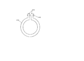
図6は本発明の実施の形態5のリングの正面図である。リング414の周の一部を切り欠いてあり、切り欠きの両端に、ほぼ放射状でリングの外側に向けて、リングと同じ巾の板415を取付けてある。2枚の板415の距離はネジ416により自在に調節することが出来るもので、これによりリング414の内径を調節が出来、モータケース231の外径とリング414の内径の精度を緩和出来るとともにリング414のモータケース231への締め付け具合を調整できる。
(Embodiment 5)
FIG. 6 is a front view of a ring according to the fifth embodiment of the present invention. A part of the circumference of the
以上のように、本発明にかかるベーンロータリ型真空ポンプは、真空ポンプ以外のポンプ等の用途にも適用できる。 As described above, the vane rotary type vacuum pump according to the present invention can be applied to uses such as pumps other than the vacuum pump.
90 ベーンロータリ型真空ポンプ
100 ポンプ機構部
111 シリンダ
121 ロータ
122 溝
123 メカシャフト
131 ベーン
141 フロントプレート
151 エンドプレート
152 転がり軸受け
161 ポンプ空間
200 モータ部
211 固定子
221 モータロータ
222 モータシャフト
231 モータケース
232 モータプレート
233 転がり軸受け
234 切り欠き
235 段付き
300 冷却回路部
311 冷却ファン
321 エアーガイド
411 リング
412 リング
413 リング
414 板
415 板
416 ねじ
90 Vane rotary
Claims (5)
5. The fastener according to claim 1, wherein a part of the circumference of the ring is cut out, and a fastener for freely adjusting the diameter of the ring is provided at both ends with the notch interposed therebetween. The vane rotary vacuum pump described in 1.
Priority Applications (1)
| Application Number | Priority Date | Filing Date | Title |
|---|---|---|---|
| JP2004077463A JP2005264802A (en) | 2004-03-18 | 2004-03-18 | Vane rotary vacuum pump |
Applications Claiming Priority (1)
| Application Number | Priority Date | Filing Date | Title |
|---|---|---|---|
| JP2004077463A JP2005264802A (en) | 2004-03-18 | 2004-03-18 | Vane rotary vacuum pump |
Publications (1)
| Publication Number | Publication Date |
|---|---|
| JP2005264802A true JP2005264802A (en) | 2005-09-29 |
Family
ID=35089623
Family Applications (1)
| Application Number | Title | Priority Date | Filing Date |
|---|---|---|---|
| JP2004077463A Pending JP2005264802A (en) | 2004-03-18 | 2004-03-18 | Vane rotary vacuum pump |
Country Status (1)
| Country | Link |
|---|---|
| JP (1) | JP2005264802A (en) |
Cited By (1)
| Publication number | Priority date | Publication date | Assignee | Title |
|---|---|---|---|---|
| JP7480604B2 (en) | 2020-06-26 | 2024-05-10 | 株式会社島津製作所 | Vacuum pump |
-
2004
- 2004-03-18 JP JP2004077463A patent/JP2005264802A/en active Pending
Cited By (1)
| Publication number | Priority date | Publication date | Assignee | Title |
|---|---|---|---|---|
| JP7480604B2 (en) | 2020-06-26 | 2024-05-10 | 株式会社島津製作所 | Vacuum pump |
Similar Documents
| Publication | Publication Date | Title |
|---|---|---|
| US10393116B2 (en) | Scroll type fluid machine | |
| JP4857910B2 (en) | Electric motor and electric compressor | |
| EP3401549B1 (en) | Turbo compressor | |
| JP2004112988A (en) | Electrically operated motor and electrically_operated compressor | |
| US20150267717A1 (en) | Turbo type fluid machine | |
| JP4804927B2 (en) | Screw compressor | |
| KR101732393B1 (en) | Scroll-type fluid machine | |
| JP6170320B2 (en) | Fixed scroll body and scroll type fluid machine | |
| JP2008106611A (en) | Centrifugal fan | |
| JP2010084592A (en) | Scroll fluid machine | |
| WO2018011970A1 (en) | Motor-integrated fluid machine | |
| WO2016199884A1 (en) | Electric compressor | |
| JP2005264802A (en) | Vane rotary vacuum pump | |
| WO2019026410A1 (en) | Oldham's ring and scroll compressor | |
| JP2008163849A (en) | Scroll type fluid machine | |
| CN110319011B (en) | Electric compressor | |
| JP4891416B2 (en) | Scroll type fluid machine | |
| CN108700068B (en) | Scroll fluid machine | |
| JP2003021065A (en) | Compressor | |
| JP2004353625A (en) | Scroll type compressor | |
| JP5455676B2 (en) | Scroll type fluid machine | |
| JP2003003979A (en) | Fluid machine | |
| JP2006017013A (en) | Scroll type fluid machine | |
| JP4410089B2 (en) | Scroll type fluid machine | |
| JP2023153688A (en) | Rotary electric machine |