JP2005258155A - Light diffusing member for transmission type screen - Google Patents
Light diffusing member for transmission type screen Download PDFInfo
- Publication number
- JP2005258155A JP2005258155A JP2004070696A JP2004070696A JP2005258155A JP 2005258155 A JP2005258155 A JP 2005258155A JP 2004070696 A JP2004070696 A JP 2004070696A JP 2004070696 A JP2004070696 A JP 2004070696A JP 2005258155 A JP2005258155 A JP 2005258155A
- Authority
- JP
- Japan
- Prior art keywords
- light
- coat layer
- light diffusing
- hard coat
- screen
- Prior art date
- Legal status (The legal status is an assumption and is not a legal conclusion. Google has not performed a legal analysis and makes no representation as to the accuracy of the status listed.)
- Pending
Links
Images


Classifications
-
- G—PHYSICS
- G02—OPTICS
- G02B—OPTICAL ELEMENTS, SYSTEMS OR APPARATUS
- G02B5/00—Optical elements other than lenses
- G02B5/02—Diffusing elements; Afocal elements
- G02B5/0205—Diffusing elements; Afocal elements characterised by the diffusing properties
- G02B5/021—Diffusing elements; Afocal elements characterised by the diffusing properties the diffusion taking place at the element's surface, e.g. by means of surface roughening or microprismatic structures
- G02B5/0226—Diffusing elements; Afocal elements characterised by the diffusing properties the diffusion taking place at the element's surface, e.g. by means of surface roughening or microprismatic structures having particles on the surface
-
- G—PHYSICS
- G02—OPTICS
- G02B—OPTICAL ELEMENTS, SYSTEMS OR APPARATUS
- G02B5/00—Optical elements other than lenses
- G02B5/02—Diffusing elements; Afocal elements
- G02B5/0205—Diffusing elements; Afocal elements characterised by the diffusing properties
- G02B5/0236—Diffusing elements; Afocal elements characterised by the diffusing properties the diffusion taking place within the volume of the element
- G02B5/0242—Diffusing elements; Afocal elements characterised by the diffusing properties the diffusion taking place within the volume of the element by means of dispersed particles
-
- G—PHYSICS
- G02—OPTICS
- G02B—OPTICAL ELEMENTS, SYSTEMS OR APPARATUS
- G02B5/00—Optical elements other than lenses
- G02B5/02—Diffusing elements; Afocal elements
- G02B5/0273—Diffusing elements; Afocal elements characterized by the use
- G02B5/0278—Diffusing elements; Afocal elements characterized by the use used in transmission
-
- G—PHYSICS
- G02—OPTICS
- G02B—OPTICAL ELEMENTS, SYSTEMS OR APPARATUS
- G02B5/00—Optical elements other than lenses
- G02B5/02—Diffusing elements; Afocal elements
- G02B5/0273—Diffusing elements; Afocal elements characterized by the use
- G02B5/0294—Diffusing elements; Afocal elements characterized by the use adapted to provide an additional optical effect, e.g. anti-reflection or filter
-
- G—PHYSICS
- G03—PHOTOGRAPHY; CINEMATOGRAPHY; ANALOGOUS TECHNIQUES USING WAVES OTHER THAN OPTICAL WAVES; ELECTROGRAPHY; HOLOGRAPHY
- G03B—APPARATUS OR ARRANGEMENTS FOR TAKING PHOTOGRAPHS OR FOR PROJECTING OR VIEWING THEM; APPARATUS OR ARRANGEMENTS EMPLOYING ANALOGOUS TECHNIQUES USING WAVES OTHER THAN OPTICAL WAVES; ACCESSORIES THEREFOR
- G03B21/00—Projectors or projection-type viewers; Accessories therefor
- G03B21/54—Accessories
- G03B21/56—Projection screens
- G03B21/60—Projection screens characterised by the nature of the surface
- G03B21/62—Translucent screens
- G03B21/625—Lenticular translucent screens
Abstract
Description
本発明は、透過型プロジェクションテレビ等に使用する透過型スクリーンに用いられる光拡散部材、ならびにその光拡散部材を用いた光学部材および透過型スクリーンに関する。 The present invention relates to a light diffusing member used for a transmissive screen used in a transmissive projection television and the like, an optical member using the light diffusing member, and a transmissive screen.
透過型プロジェクションテレビは、CRT、液晶プロジェクター、DLP等の光源からの画像を透過型スクリーン上に拡大投影する表示装置である。このような表示装置において、スクリーンを目視した際の眩しさを低減するために、出射光を拡散させるための光拡散板等がスクリーン表面に設けられている。また、外光のスクリーン表面への映り込みによる投影画像の視認性悪化を低減するため、スクリーン表面には反射防止膜が設けられることもある。このような光拡散板や反射防止膜は、例えば、特開平11−295818号公報(特許文献1)や特開平7−28169号公報(特許文献2)に開示されているように、これら光拡散板等を構成する樹脂中に有機フィラー等の透明性微粒子を含有させることにより作製されている。また、透明性微粒子を樹脂表面に突出させることにより光拡散板の表面を凹凸状に形成することにより、反射防止効果も併せ持つものが開発されている。 A transmissive projection television is a display device that enlarges and projects an image from a light source such as a CRT, a liquid crystal projector, or a DLP onto a transmissive screen. In such a display device, a light diffusing plate or the like for diffusing outgoing light is provided on the screen surface in order to reduce glare when the screen is viewed. In addition, an antireflection film may be provided on the screen surface in order to reduce the deterioration of the visibility of the projected image due to the reflection of external light on the screen surface. Such a light diffusing plate and antireflection film are, for example, disclosed in Japanese Patent Application Laid-Open No. 11-295818 (Patent Document 1) and Japanese Patent Application Laid-Open No. 7-28169 (Patent Document 2). It is produced by including transparent fine particles such as an organic filler in a resin constituting a plate or the like. Moreover, what has an anti-reflective effect is also developed by forming the surface of a light-diffusion plate in uneven | corrugated shape by making transparent fine particles protrude on the resin surface.
しかしながら、スクリーン表面を保護するために、上記の光拡散板の表面に保護層(ハードコート層ともいう)を設けると、光拡散板表面の凹凸形状がなくなってしまい、反射防止効果が得られないといった問題があった。 However, if a protective layer (also referred to as a hard coat layer) is provided on the surface of the light diffusing plate in order to protect the screen surface, the irregular shape on the surface of the light diffusing plate is lost, and an antireflection effect cannot be obtained. There was a problem.
一方、反射防止効果を奏する程度に保護層を設けようとすると、光拡散板表面の凹凸程度、すなわち、透明微粒子の粒子径よりも保護層の厚みを薄くしなければならず、十分な表面保護効果が得られないといった問題があった。
本発明者らは今般、光拡散板にハードコート層を設ける際に、基材中に含まれる微粒子の粒径および含有量と、ハードコート層を形成する樹脂の厚みとを調整することにより、ハードコート層の表面硬度および表面光沢度を制御でき、反射防止効果を維持しながら十分な表面保護効果を有する光拡散部材が実現できる、との知見を得た。本発明は、かかる知見に基づくものである。 In general, when the present inventors provide a hard coat layer on the light diffusing plate, by adjusting the particle size and content of fine particles contained in the substrate and the thickness of the resin forming the hard coat layer, It was found that the surface hardness and surface glossiness of the hard coat layer can be controlled, and a light diffusing member having a sufficient surface protection effect while maintaining the antireflection effect can be realized. The present invention is based on such knowledge.
従って、本発明は、反射防止効果を維持しながら優れた表面保護効果も併せ持つ、透過型スクリーンに用いられる光拡散部材を提供することにある。 Accordingly, it is an object of the present invention to provide a light diffusing member for use in a transmissive screen that has an excellent surface protection effect while maintaining an antireflection effect.
そして、本発明による透過型スクリーン用光拡散部材は、少なくとも一層以上からなる基材表面に、ハードコート層が設けられてなる透過型スクリーン用光拡散部材であって、前記基材に微粒子が含まれてなり、前記ハードコート層の表面光沢度が、入射角60°/反射角60°の測定条件にて、光沢標準板の表面光沢度を100とした場合に、60〜80であるものである。また、好ましい態様としては、前記ハードコート層の表面硬度が、JIS K5600-5-4に準拠した鉛筆硬度試験において3H以上である。上記のような表面硬度を有するハードコート層を観察者側(最表面)に設けることにより、反射防止効果を維持しつつ、十分な表面保護効果を実現できる。 The light diffusing member for a transmissive screen according to the present invention is a light diffusing member for a transmissive screen in which a hard coat layer is provided on the surface of a substrate composed of at least one layer, and the substrate contains fine particles. The surface glossiness of the hard coat layer is 60 to 80 when the glossiness standard plate surface glossiness is 100 under the measurement conditions of an incident angle of 60 ° / reflection angle of 60 °. is there. In a preferred embodiment, the hard coat layer has a surface hardness of 3H or more in a pencil hardness test in accordance with JIS K5600-5-4. By providing the hard coat layer having the surface hardness as described above on the viewer side (outermost surface), a sufficient surface protection effect can be realized while maintaining the antireflection effect.
以下、本発明による光拡散部材について説明する。 Hereinafter, the light diffusing member according to the present invention will be described.
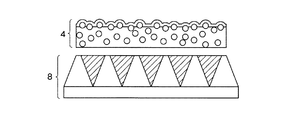
本発明による光拡散部材は、図1に示すように微粒子2を含有した基材1の表面にハードコート層3が設けられた構造を有し、ハードコート層が観察者側の最前面に設けられている。ここで、観察者側の最前面とは、当該光拡散部材を透過型スクリーンに組み込んだ場合の、透過光を観察する側の最表面に位置していることを意味するものである。
The light diffusing member according to the present invention has a structure in which a
本発明による光拡散部材は、基材上に設けたハードコート層の表面光沢度が、入射角60°/反射角60°の測定条件にて、60〜80である。ここで、表面光沢度とは、JIS K5600-4-7に準拠した屈折率1.567のガラス板を標準光沢板として、標準光沢板の表面光沢度を100とした場合の相対的な値を意味するものである。本発明の光拡散部材を構成するハードコート層の表面光沢度が60〜80であれば、透過型スクリーン用途として優れた反射防止効果が得られる。表面光沢度が60未満であると、ハードコート層表面での光拡散が顕著になるためヘイズ値が上昇し、スクリーンとしての光線透過率が低下する。一方、80を超えると、ハードコート層表面での光の正反射が支配的になるため、スクリーンの外光の映り込みが発生してしまう。なお、表面光沢度は、一般的な光沢度計(例えば、ハンディー光沢計:GLOSS CHECKER IG-330、三和研磨製)を用いて測定することができる。ハードコート層が、上記のような表面硬度と表面光沢度を備えるためには、基材中に含まれる微粒子の粒径および含有量と、ハードコート層を形成する樹脂の厚みとが、下記に説明するような範囲でなければならない。 In the light diffusing member according to the present invention, the surface glossiness of the hard coat layer provided on the substrate is 60 to 80 under the measurement conditions of an incident angle of 60 ° and a reflection angle of 60 °. Here, the surface glossiness is a relative value when a glass plate having a refractive index of 1.567 in accordance with JIS K5600-4-7 is a standard glossy plate and the surface glossiness of the standard glossy plate is 100. That means. If the surface glossiness of the hard coat layer constituting the light diffusing member of the present invention is 60 to 80, an excellent antireflection effect can be obtained as a transmissive screen application. When the surface glossiness is less than 60, light diffusion on the surface of the hard coat layer becomes remarkable, so that the haze value increases and the light transmittance as a screen decreases. On the other hand, if it exceeds 80, regular reflection of light on the surface of the hard coat layer becomes dominant, and reflection of outside light on the screen occurs. The surface glossiness can be measured using a general glossiness meter (for example, handy gloss meter: GLOSS CHECKER IG-330, manufactured by Sanwa Abrasive). In order for the hard coat layer to have surface hardness and surface gloss as described above, the particle size and content of the fine particles contained in the substrate and the thickness of the resin forming the hard coat layer are as follows: It must be in the range described.
ハードコート層3は、その厚みが、3〜15μmであることが好ましい。ハードコート層の厚みがこの程度であれば、基材の材質に寄らず、ハードコート層の表面硬度をJIS K5600-5-4に準拠した鉛筆硬度試験において3H以上とすることができる。ハードコート層の厚みが、3μm未満であると下面の基材の材質の硬さに影響を受け、十分な表面硬度を実現できず、スクリーンの傷つき防止効果が得られない。一方、15μmを超えると、ハードコート層の厚みが厚くなりすぎ、基材表面の微粒子により形成された凹凸形状が、ハードコート層表面にトレースされなくなり、結果として反射防止効果が期待できなくなる。ハードコート層の厚みは、5〜10μmであることがより好ましい。
The
また、基材1に含有される微粒子2は、その平均粒径が、5〜15μmであることが好ましい。5μm未満であると、ハードコート層を設けた場合に、ハードコート層表面が平滑になりすぎるため、反射防止効果が得られなくなる。一方、微粒子の平均粒径が15μmを超えると、ハードコート層表面が粗くなり反射防止効果が低減してしまう。
Moreover, it is preferable that the average particle diameter of the microparticles | fine-
さらに、前記微粒子は、基材に対して10〜20重量%含まれていることが好ましい。20重量%を超えると、微粒子による光拡散効果が大きすぎるため透過型スクリーンとしてのヘイズ値が増加し、十分な透過率が得られなくなる。一方、10重量%未満であると、光拡散効果が十分に得られず、またハードコート層の表面光沢度が80を超えてしまう。 Further, the fine particles are preferably contained in an amount of 10 to 20% by weight based on the base material. If it exceeds 20% by weight, the light diffusing effect by the fine particles is too great, so that the haze value as a transmission screen increases and sufficient transmittance cannot be obtained. On the other hand, if it is less than 10% by weight, the light diffusion effect cannot be sufficiently obtained, and the surface glossiness of the hard coat layer exceeds 80.
本発明に用いられる基材としては、透明樹脂フィルム、透明樹脂板、透明樹脂シートや透明ガラスを用いることができる。透明樹脂フィルムとしては、トリアセテートセルロース(TAC)フィルム、ポリエチレンテレフタレート(PET)フィルム、ジアセチルセルロースフィルム、アセテートブチレートセルロースフィルム、ポリエーテルサルホンフィルム、ポリアクリル系樹脂フィルム、ポリウレタン系樹脂フィルム、ポリエステルフィルム、ポリカーボネートフィルム、ポリスルホンフィルム、ポリエーテルフィルム、ポリメチルペンテンフィルム、ポリエーテルケトンフィルム、(メタ)アクリルロニトリルフィルム等を好適に使用できる。基材の厚さは通常0.025mm〜2mm程度である。 As a base material used for this invention, a transparent resin film, a transparent resin board, a transparent resin sheet, and transparent glass can be used. As transparent resin film, triacetate cellulose (TAC) film, polyethylene terephthalate (PET) film, diacetyl cellulose film, acetate butyrate cellulose film, polyether sulfone film, polyacrylic resin film, polyurethane resin film, polyester film, A polycarbonate film, a polysulfone film, a polyether film, a polymethylpentene film, a polyether ketone film, a (meth) acrylonitrile film, or the like can be suitably used. The thickness of the substrate is usually about 0.025 mm to 2 mm.
本発明に用いられる基材1に含有させる微粒子2としては、プラスチックビーズ等の有機フィラーが好適であり、特に透明度が高く、後述のハードコート層との屈折率差が0.05程度であるものが好ましい。
As the
プラスチックビーズとしては、メラミンビーズ(屈折率1.57)、アクリルビーズ(屈折率1.49)、ポリカーボネートビーズ、ポリエチレンビーズ、ポリスチレンビーズ(1.60)、塩ビビーズ等や、アクリル−スチレンビーズ等の共重合体樹脂からなるビーズを好適に使用できる。これら共重合体樹脂からなるビーズは、各モノマーの含有率により、屈折率を変えることができる。これらの中でもアクリルビーズ、またはメタクリル−スチレン共重合体(MS)ビーズが好ましい。プラスチックビーズの粒径は、前述のように5〜15μmのものを用いる。 Plastic beads include melamine beads (refractive index 1.57), acrylic beads (refractive index 1.49), polycarbonate beads, polyethylene beads, polystyrene beads (1.60), polyvinyl chloride beads, acrylic-styrene beads, etc. Beads made of a copolymer resin can be suitably used. The refractive index of the beads made of these copolymer resins can be changed depending on the content of each monomer. Among these, acrylic beads or methacryl-styrene copolymer (MS) beads are preferable. The particle diameter of the plastic beads is 5 to 15 μm as described above.
本発明においては、図1に示すように基材1を一層としてハードコート層3を設けてもよいが、図2に示すように、基材1aと基材1bとの二層の構成としても良い。基材1aに含まれる微粒子の含有量は、上記で説明した範囲とする必要があるが、基材1bに含まれる微粒子の含有量は、基材1a中の微粒子含有量よりも少なくすることが好ましい。基材1b中の微粒子含有量を少なくすることにより、後述する水平方向視野角拡大部材等の光学部材を組み合わせた際に、その接合面が平滑になるため、光拡散部材4と光学部材との密着性が高まる。
In the present invention, the
本発明による光拡散部材を構成するハードコート層は、紫外線・電子線によって硬化する樹脂、即ち、電離放射線硬化型樹脂、電離放射線硬化型樹脂に熱可塑性樹脂と溶剤を混合したもの、および熱硬化型樹脂を用いることができるが、これらの中でも電離放射線硬化型樹脂が特に好ましい。 The hard coat layer constituting the light diffusing member according to the present invention is a resin curable by ultraviolet rays or electron beams, that is, an ionizing radiation curable resin, a mixture of an ionizing radiation curable resin and a thermoplastic resin and a solvent, and thermosetting. Of these, ionizing radiation curable resins are particularly preferred.
電離放射線硬化型樹脂組成物の被膜形成成分は、好ましくは、アクリレート系の官能基を有するもの、例えば比較的低分子量のポリエステル樹脂、ポリエーテル樹脂、アクリル樹脂、エポキシ樹脂、ウレタン樹脂、アルキッド樹脂、スピロアセタール樹脂、ポリブタジェン樹脂、ポリチオールポリエン樹脂、多価アルコール等の多官能化合物の(メタ)アルリレート等のオリゴマー又はプレポリマー及び反応性希釈剤としてエチル(メタ)アクリレート、エチルヘキシル(メタ)アクリレート、スチレン、メチルスチレン、N−ビニルピロリドン等の単官能モノマー並びに多官能モノマー、例えば、ポリメチロールプロパントリ(メタ)アクリレート、ヘキサンジオール(メタ)アクリレート、トリプロピレングリコールジ(メタ)アクリレート、ジエチレングリコールジ(メタ)アクリレート、ペンタエリスリトールトリ(メタ)アクリレート、ジペンタエリスリトールヘキサ(メタ)アクリレート、1,6−ヘキサンジオールジ(メタ)アクリレート、ネオペンチルグリコールジ(メタ)アクリレート等を比較的多量に含有するものが使用できる。 The film forming component of the ionizing radiation curable resin composition is preferably one having an acrylate functional group, such as a relatively low molecular weight polyester resin, polyether resin, acrylic resin, epoxy resin, urethane resin, alkyd resin, Spiroacetal resin, polybutadiene resin, polythiol polyene resin, oligomers or prepolymers of polyfunctional compounds such as polyhydric alcohols such as (meth) allylates and reactive diluents such as ethyl (meth) acrylate, ethylhexyl (meth) acrylate, styrene, Monofunctional monomers such as methylstyrene and N-vinylpyrrolidone as well as polyfunctional monomers such as polymethylolpropane tri (meth) acrylate, hexanediol (meth) acrylate, tripropylene glycol di (meth) acrylate Diethylene glycol di (meth) acrylate, pentaerythritol tri (meth) acrylate, dipentaerythritol hexa (meth) acrylate, 1,6-hexanediol di (meth) acrylate, neopentyl glycol di (meth) acrylate, etc. A large amount can be used.
上記電離放射線硬化型樹脂組成物を紫外線硬化型樹脂組成物とするには、この中に光重合開始剤としてアセトフェノン類、ベンゾフェノン類、ミヒラーベンゾイルベンゾエート、α−アミロキシムエステル、テトラメチルチュウラムモノサルファイド、チオキサントン類や、光増感剤としてn−ブチルアミン、トリエチルアミン、ポリ−n−ブチルホソフィン等を混合して用いることができる。特に本発明では、オリゴマーとしてウレタンアクリレート、モノマーとしてジペンタエリスリトールヘキサ(メタ)アクリレート等を混合するのが好ましい。 In order to make the ionizing radiation curable resin composition into an ultraviolet curable resin composition, acetophenones, benzophenones, Michler benzoyl benzoate, α-amyloxime ester, tetramethylchuram mono are used as photopolymerization initiators. A mixture of sulfides, thioxanthones, n-butylamine, triethylamine, poly-n-butylphosphine, or the like as a photosensitizer can be used. In particular, in the present invention, it is preferable to mix urethane acrylate as an oligomer and dipentaerythritol hexa (meth) acrylate as a monomer.
電離放射線硬化型樹脂組成物の硬化方法としては、前記電離放射線硬化型樹脂組成物の硬化方法は通常の硬化方法、即ち、電子線又は紫外線の照射によって硬化することができる。 As a curing method of the ionizing radiation curable resin composition, the curing method of the ionizing radiation curable resin composition can be cured by a normal curing method, that is, irradiation with an electron beam or ultraviolet rays.
例えば、電子線硬化の場合には、コックロフトワルトン型、バンデグラフ型、共振変圧型、絶縁コア変圧器型、直線型、ダイナミトロン型、高周波型等の各種電子線加速機から放出される50〜1000KeV、好ましくは100〜300KeVのエネルギーを有する電子線等が使用され、紫外線硬化の場合には超高圧水銀灯、高圧水銀灯、低圧水銀灯、カーボンアーク、キセノンアーク、メタルハライドランプ等の光線から発する紫外線等が利用できる。 For example, in the case of electron beam curing, 50 to 50 emitted from various electron beam accelerators such as a Cockloft Walton type, a bandegraph type, a resonant transformation type, an insulating core transformer type, a linear type, a dynamitron type, and a high frequency type An electron beam having an energy of 1000 KeV, preferably 100 to 300 KeV is used, and in the case of ultraviolet curing, ultraviolet rays emitted from rays such as an ultrahigh pressure mercury lamp, a high pressure mercury lamp, a low pressure mercury lamp, a carbon arc, a xenon arc, a metal halide lamp, etc. Available.
本発明による光拡散部材を構成するハードコート層は、基材上に上記電離放射(紫外線)線硬化型樹脂組成物の塗工液をスピンコート、ダイコート、ディップコート、バーコート、フローコート、ロールコート、グラビアコート等の方法で、基材の表面に塗布し、上記のような手段で塗工液を硬化させることにより形成することができる。 The hard coat layer constituting the light diffusing member according to the present invention is a spin coat, die coat, dip coat, bar coat, flow coat, roll of the above ionizing radiation (ultraviolet) ray curable resin composition coating solution on a substrate. It can be formed by applying to the surface of the substrate by a method such as coating or gravure coating and curing the coating solution by the means described above.
次に、本発明による光拡散部材を用いた透過型スクリーンについて説明する。 Next, a transmissive screen using the light diffusing member according to the present invention will be described.
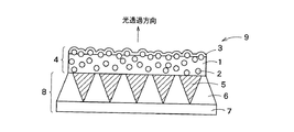
本発明による光拡散部材4は、図3に示されるように水平方向視野角拡大部材8と組み合わせて用いることができる。本発明にあっては、光拡散部材が光透過方向の最前面に配置されている。図3の光学部材9は、光透過方向の最前面に光拡散部材4が設けられてなるものである。水平方向視野角拡大部材8は、通常レンズ基材7上にレンズ6を設けた構造を有する。本発明においては、図3に示すように、透明樹脂部6と光吸収部(遮光部)5との境界面が反射面となったものとを組み合わせてレンズ機能を発現させ、このような透明樹脂部と光吸収部とをレンズ基材7上に設けて、水平方向視野角拡大部材8として良い。本発明にあっては、このように水平方向視野角拡大部材8と光拡散部材4とを組み合わせることにより、スクリーンへの外光の映り込みが無く視認性に優れ、コントラストが良好でシャープ感のある画像を実現することができる。
The
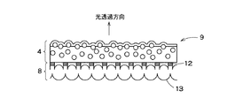
また、本発明においては、光拡散部材を図4に示すようにシリンドリカルレンズ部材11と組み合わせて光学部材を構成しても良い。シリンドリカルレンズ部材11は、レンズ基材10の一方の面に設けられており、他方の面には光吸収部(遮光部)12が設けられた構造を有している。シリンドリカルレンズ部材と光吸収部とを組み合わせた水平方向視野角拡大部材としては、図5に示すように、レンチキュラーレンズ部材13を用いても良い。
In the present invention, the light diffusing member may be combined with the
さらに、上記の光拡散部材を用いた光学部材は、粘着層(図示せず)を介して光拡散部材とレンズ部材とが接着されていてもよく、また、図6〜8に示すように、光拡散部材と、水平方向視野角拡大部材またはレンズ部材とが、接着されてない状態で組み合わされてもよい。 Furthermore, in the optical member using the above light diffusing member, the light diffusing member and the lens member may be bonded via an adhesive layer (not shown), and as shown in FIGS. The light diffusing member and the horizontal viewing angle enlarging member or the lens member may be combined in a state where they are not adhered.
本発明による透過型スクリーンは、図9〜11に示すように、上記光学部材とフレネルレンズ部材14とを組み合わせた構造を有するものである。本発明にあっては、表面硬度3H以上のハードコート層を設けた光拡散部材4が、透過型スクリーンの最表面(観察者側)に配置されていることにより、外光等がスクリーンに映り込むことがなく、かつ、スクリーン表面に傷が付きにくい、透過型スクリーンを実現することができる。
As shown in FIGS. 9 to 11, the transmission screen according to the present invention has a structure in which the optical member and the
以下、実施例により本発明を更に詳細に説明するが、これら実施例に本発明が限定されるものではない。 EXAMPLES Hereinafter, although an Example demonstrates this invention further in detail, this invention is not limited to these Examples.
光拡散部材の基材に用いる樹脂としてMS(メタクリル−スチレン共重合体)樹脂(屈折率1.53)を用いた。基材中に添加する微粒子としてMSビーズ(屈折率1.49、平均粒径10μm)を用い、基材に対する微粒子添加量が15重量%となるように加えた。これら混合物を溶融押出機により押出成形を行い、光拡散部材の基材を作製した。 MS (methacryl-styrene copolymer) resin (refractive index 1.53) was used as the resin used for the base material of the light diffusing member. MS beads (refractive index: 1.49, average particle size: 10 μm) were used as fine particles to be added to the substrate, and the addition amount of fine particles to the substrate was 15% by weight. These mixtures were extruded using a melt extruder to produce a base material for a light diffusing member.
次に、この基材の表面に、ウレタンアクリレートを主成分とする紫外線硬化性樹脂組成物をディップコート法により塗布し、紫外線を照射して樹脂組成物を硬化させて基材上にハードコート層を形成し、光拡散部材を得た。ハードコート層の厚みは、ハードコート層をディップコート法により形成する際に、コート液層から基材を引き上げる速度を調節することにより調整を行った。同様の方法にて、ハードコート層の厚みを変えた光拡散部材を作製した。ハードコート層の各膜厚は表1に示される通りであった。 Next, an ultraviolet curable resin composition containing urethane acrylate as a main component is applied to the surface of the substrate by a dip coating method, and the resin composition is cured by irradiating ultraviolet rays to form a hard coat layer on the substrate. And a light diffusing member was obtained. The thickness of the hard coat layer was adjusted by adjusting the speed at which the substrate was pulled up from the coating liquid layer when the hard coat layer was formed by the dip coating method. In the same manner, light diffusing members having different hard coat layer thicknesses were produced. Each film thickness of the hard coat layer was as shown in Table 1.
次に、得られた光拡散部材について、表面光沢度計(ハンディー光沢計GLOSS CHECKER IG-330:三和研磨製)を用いて、入射角60°/反射角60°の測定条件にて、ハードコート層が設けられた側の面の表面光沢度を測定した。 Next, with respect to the obtained light diffusing member, using a surface gloss meter (GLOSS CHECKER IG-330, manufactured by Sanwa Abrasive Co., Ltd.) The surface glossiness of the surface on which the coat layer was provided was measured.
また、光拡散部材のハードコート層が設けられた側の面について、鉛筆引っかき試験を、JIS K5600-5-4に準拠した方法により行った。 Further, a pencil scratch test was performed on the surface of the light diffusing member on which the hard coat layer was provided by a method based on JIS K5600-5-4.
さらに、レンチキュラーレンズシートとフレネルレンズシートとを組み合わせ、該レンチキュラーレンズ側に、得られた光拡散部材を組み込み、透過型スクリーンを作製した。作製したスクリーンの画質についての官能評価を行った。また、得られた透過型スクリーンに画像を投影した状態で、スクリーン表面(光拡散部材側)に外光を当て、スクリーン表面への外光の映り込みについて評価を行った。 Further, a lenticular lens sheet and a Fresnel lens sheet were combined, and the obtained light diffusion member was incorporated on the lenticular lens side to produce a transmission type screen. Sensory evaluation was performed on the image quality of the produced screen. Moreover, in the state which projected the image on the obtained transmission type screen, external light was applied to the screen surface (light-diffusion member side), and the reflection of external light on the screen surface was evaluated.
評価基準は以下の通りとした。 The evaluation criteria were as follows.
1.画質評価
○:スクリーンの画面が明るく、画像の輪郭がくっきりしていたもの
△:スクリーンの画面がやや白く、画像の輪郭がややぼやけていたもの
×:スクリーンの画面が白っぽく、画像の輪郭がぼやけていたもの
2.スクリーン表面への外光映り込み評価
○:映り込みが弱く、画像の視認性が良好であったもの
△:映り込みがあるが、画像の視認性が普通であったもの
×:映り込みが非常に強く、画像の視認性が悪かったもの
測定結果および評価結果は表1に示される通りであった。

1、1a、1b 基材
2 微粒子
3 ハードコート層
4 光拡散部材
5 光吸収部
6 レンズ部
7 レンズ基材
8 水平方向視野角拡大部材
9 光学部材
10 レンズ基材
11 シリンドリカルレンズ部材
12 光吸収部
13 レンチキュラーレンズ部材
14 フレネルレンズ部材
DESCRIPTION OF
Claims (12)
Priority Applications (5)
| Application Number | Priority Date | Filing Date | Title |
|---|---|---|---|
| JP2004070696A JP2005258155A (en) | 2004-03-12 | 2004-03-12 | Light diffusing member for transmission type screen |
| TW094107542A TWI270692B (en) | 2004-03-12 | 2005-03-11 | Transmitting screen-use light diffusing member |
| US10/591,721 US20070273974A1 (en) | 2004-03-12 | 2005-03-11 | Light Diffusing Member For Transmission Screen |
| PCT/JP2005/004287 WO2005088356A1 (en) | 2004-03-12 | 2005-03-11 | Transmitting screen-use light diffusing member |
| CNB2005800076442A CN100434942C (en) | 2004-03-12 | 2005-03-11 | Transmitting screen-use light diffusing member |
Applications Claiming Priority (1)
| Application Number | Priority Date | Filing Date | Title |
|---|---|---|---|
| JP2004070696A JP2005258155A (en) | 2004-03-12 | 2004-03-12 | Light diffusing member for transmission type screen |
Publications (1)
| Publication Number | Publication Date |
|---|---|
| JP2005258155A true JP2005258155A (en) | 2005-09-22 |
Family
ID=34975723
Family Applications (1)
| Application Number | Title | Priority Date | Filing Date |
|---|---|---|---|
| JP2004070696A Pending JP2005258155A (en) | 2004-03-12 | 2004-03-12 | Light diffusing member for transmission type screen |
Country Status (5)
| Country | Link |
|---|---|
| US (1) | US20070273974A1 (en) |
| JP (1) | JP2005258155A (en) |
| CN (1) | CN100434942C (en) |
| TW (1) | TWI270692B (en) |
| WO (1) | WO2005088356A1 (en) |
Cited By (3)
| Publication number | Priority date | Publication date | Assignee | Title |
|---|---|---|---|---|
| JP2007133209A (en) * | 2005-11-11 | 2007-05-31 | Dainippon Printing Co Ltd | Surface protection sheet and transmission type screen |
| WO2009107536A1 (en) * | 2008-02-27 | 2009-09-03 | 住友化学株式会社 | Anti-glare film, anti-glare polarizing plate, and image display device |
| JP2012145748A (en) * | 2011-01-12 | 2012-08-02 | Dainippon Printing Co Ltd | Antireflection film and method of manufacturing the same |
Families Citing this family (6)
| Publication number | Priority date | Publication date | Assignee | Title |
|---|---|---|---|---|
| KR100920371B1 (en) * | 2006-11-10 | 2009-10-07 | 도레이새한 주식회사 | Light-diffusing film for direct back light unit of lcd |
| CN101910877B (en) * | 2008-10-21 | 2014-10-01 | 大日本印刷株式会社 | Optical sheet |
| US20110043542A1 (en) * | 2009-07-06 | 2011-02-24 | Tsuyoshi Kashiwagi | Display device |
| WO2013129290A1 (en) * | 2012-03-02 | 2013-09-06 | 三菱製紙株式会社 | Transmissive type screen |
| CN108627898A (en) * | 2017-03-24 | 2018-10-09 | 张家港康得新光电材料有限公司 | A kind of anti-sticking brightness enhancement film of high briliancy and backlight module |
| JPWO2021039182A1 (en) * | 2019-08-27 | 2021-03-04 |
Family Cites Families (20)
| Publication number | Priority date | Publication date | Assignee | Title |
|---|---|---|---|---|
| JPS5618032B2 (en) * | 1973-07-05 | 1981-04-25 | ||
| ES2111585T3 (en) * | 1991-06-21 | 1998-03-16 | Hoechst Ag | COMPOSITION OF POLY (OXYMETHYLENE) AND ITS USE. |
| US5481385A (en) * | 1993-07-01 | 1996-01-02 | Alliedsignal Inc. | Direct view display device with array of tapered waveguide on viewer side |
| JP2790032B2 (en) * | 1994-03-11 | 1998-08-27 | 松下電器産業株式会社 | Transmission screen and manufacturing method thereof |
| US5745288A (en) * | 1994-05-02 | 1998-04-28 | Dai Nippon Printing Co., Ltd. | Transmission type projection screen |
| JPH10325901A (en) * | 1997-05-26 | 1998-12-08 | Toppan Printing Co Ltd | Antidazzle hard coating film or sheet and its production |
| JP4075147B2 (en) * | 1998-08-04 | 2008-04-16 | 凸版印刷株式会社 | Hard coat film or sheet, and hard coat film or sheet with functional inorganic thin film |
| JP2000056104A (en) * | 1998-08-04 | 2000-02-25 | Nitto Denko Corp | Light diffusing layer, optical device and liquid crystal display device |
| KR20010099829A (en) * | 1998-12-18 | 2001-11-09 | 추후제출 | Transmission screen |
| US6307675B1 (en) * | 1998-12-24 | 2001-10-23 | Toppan Printing Co. Ltd. | Rear-projection screen for use with a liquid crystal panel as a video source |
| KR100737229B1 (en) * | 1999-02-05 | 2007-07-09 | 후지필름 홀딩스 가부시끼가이샤 | Matlike high-transmittance film, polarization plate and liquid crystal display device using the same |
| JP2001305314A (en) * | 2000-04-19 | 2001-10-31 | Nitto Denko Corp | Antiglare layer, antiglare film and optical device |
| JP2002056104A (en) * | 2000-08-07 | 2002-02-20 | Saitetsu Cho | System for registration, retrieval, and management of medical database using on-line system |
| JP2002196117A (en) * | 2000-12-25 | 2002-07-10 | Nitto Denko Corp | Light diffusion layer, light diffusing sheet and optical element |
| JP2002248712A (en) * | 2001-02-23 | 2002-09-03 | Toppan Printing Co Ltd | Anti-glaring sheet |
| CN1360214A (en) * | 2001-11-15 | 2002-07-24 | 曹贤明 | Light splitting film |
| CN1646949A (en) * | 2002-04-25 | 2005-07-27 | 日东电工株式会社 | Light-diffusing sheet, optical element, and image display |
| DE10336129A1 (en) * | 2003-08-04 | 2005-02-24 | Röhm GmbH & Co. KG | Back projection screen for LCD monitors comprises at least one light scattering polymethylmethacrylate layer containing spherical particles (A) and spherical particles (B) having different average particle sizes |
| JP2005352238A (en) * | 2004-06-11 | 2005-12-22 | Dainippon Printing Co Ltd | Light diffusing member |
| JP2005352275A (en) * | 2004-06-11 | 2005-12-22 | Dainippon Printing Co Ltd | Surface protecting member for transmission type screen |
-
2004
- 2004-03-12 JP JP2004070696A patent/JP2005258155A/en active Pending
-
2005
- 2005-03-11 US US10/591,721 patent/US20070273974A1/en not_active Abandoned
- 2005-03-11 TW TW094107542A patent/TWI270692B/en not_active IP Right Cessation
- 2005-03-11 WO PCT/JP2005/004287 patent/WO2005088356A1/en not_active Application Discontinuation
- 2005-03-11 CN CNB2005800076442A patent/CN100434942C/en not_active Expired - Fee Related
Cited By (3)
| Publication number | Priority date | Publication date | Assignee | Title |
|---|---|---|---|---|
| JP2007133209A (en) * | 2005-11-11 | 2007-05-31 | Dainippon Printing Co Ltd | Surface protection sheet and transmission type screen |
| WO2009107536A1 (en) * | 2008-02-27 | 2009-09-03 | 住友化学株式会社 | Anti-glare film, anti-glare polarizing plate, and image display device |
| JP2012145748A (en) * | 2011-01-12 | 2012-08-02 | Dainippon Printing Co Ltd | Antireflection film and method of manufacturing the same |
Also Published As
| Publication number | Publication date |
|---|---|
| CN100434942C (en) | 2008-11-19 |
| WO2005088356A1 (en) | 2005-09-22 |
| CN1930498A (en) | 2007-03-14 |
| US20070273974A1 (en) | 2007-11-29 |
| TW200600837A (en) | 2006-01-01 |
| TWI270692B (en) | 2007-01-11 |
Similar Documents
| Publication | Publication Date | Title |
|---|---|---|
| US7345819B2 (en) | Light diffusing member | |
| US8634136B2 (en) | Transmission screen for interactive board | |
| US7342720B2 (en) | Surface protective member for transmission screen | |
| TWI270692B (en) | Transmitting screen-use light diffusing member | |
| EP1632796A1 (en) | Light-diffusing film and screen including the same | |
| JP2012048223A (en) | Light-diffusing film and method for manufacturing the same, light-diffusing polarizing plate and liquid crystal display device | |
| JPWO2007004679A1 (en) | Rear projection TV screen | |
| JP2006227279A (en) | Light diffusion sheet and transparent screen | |
| JP2005241920A (en) | Light diffusing screen | |
| US20120064297A1 (en) | Fine particle for optical function layer, optical member for display, and glare shield function layer | |
| JP2009116336A (en) | Glare-proof film, polarizing plate and transmission type display device | |
| KR20070027547A (en) | Fresnel lens sheet and transmission type screen | |
| JP4159314B2 (en) | Anti-glare film | |
| JP2014077883A (en) | Reflection screen, video display system | |
| KR20190009241A (en) | Polarizing plate and optical display device comprising the same | |
| KR100859365B1 (en) | Transmitting screen-use light diffusing member | |
| JP6287007B2 (en) | Reflective screen and video display system with reflective screen | |
| JP2008107835A (en) | Surface protecting member for translucent screen | |
| JP2007293171A (en) | Reflection type projection screen and video display apparatus | |
| KR20070110173A (en) | Projection screen | |
| JP2006267948A (en) | Transmission type screen | |
| JP2007212825A (en) | Transmission type screen | |
| JP2007127859A (en) | Light diffusion plate and coating liquid for forming the same | |
| JP2000187283A (en) | Transmission type screen | |
| JP2016061906A (en) | Translucent screen, display device, and manufacturing method for translucent screen |
Legal Events
| Date | Code | Title | Description |
|---|---|---|---|
| A131 | Notification of reasons for refusal |
Free format text: JAPANESE INTERMEDIATE CODE: A131 Effective date: 20071221 |
|
| A521 | Written amendment |
Free format text: JAPANESE INTERMEDIATE CODE: A523 Effective date: 20080219 |
|
| A02 | Decision of refusal |
Free format text: JAPANESE INTERMEDIATE CODE: A02 Effective date: 20080404 |
|
| A521 | Written amendment |
Free format text: JAPANESE INTERMEDIATE CODE: A523 Effective date: 20080604 |
|
| A911 | Transfer to examiner for re-examination before appeal (zenchi) |
Free format text: JAPANESE INTERMEDIATE CODE: A911 Effective date: 20080716 |
|
| A912 | Re-examination (zenchi) completed and case transferred to appeal board |
Free format text: JAPANESE INTERMEDIATE CODE: A912 Effective date: 20080919 |