JP2005247194A - Electric parking brake device - Google Patents
Electric parking brake device Download PDFInfo
- Publication number
- JP2005247194A JP2005247194A JP2004062367A JP2004062367A JP2005247194A JP 2005247194 A JP2005247194 A JP 2005247194A JP 2004062367 A JP2004062367 A JP 2004062367A JP 2004062367 A JP2004062367 A JP 2004062367A JP 2005247194 A JP2005247194 A JP 2005247194A
- Authority
- JP
- Japan
- Prior art keywords
- parking brake
- ecu
- brake device
- electric parking
- driver
- Prior art date
- Legal status (The legal status is an assumption and is not a legal conclusion. Google has not performed a legal analysis and makes no representation as to the accuracy of the status listed.)
- Pending
Links
Images


Abstract
Description
本発明は、電動パーキングブレーキ装置に関する。 The present invention relates to an electric parking brake device.
従来、乗員の手動操作に代えて、電動にてパーキングブレーキの作動及び解除をする電動パーキングブレーキ装置が知られている。また、従来の電動パーキングブレーキ装置としては、パーキングブレーキの解除操作が可能なパーキングスイッチを備え、このパーキングスイッチでパーキングブレーキの解除操作が行われた際に、パーキングブレーキを解除するものが知られている(例えば、特許文献1参照)。
しかしながら、従来の電動パーキングブレーキ装置では、運転者以外の乗員(例えば子供や犬)が誤ってパーキングスイッチでパーキングブレーキの解除操作をしてしまう可能性があった。したがって、運転者の意図しないパーキングブレーキの解除が起こる可能性があった。 However, in the conventional electric parking brake device, there is a possibility that an occupant other than the driver (for example, a child or a dog) may accidentally release the parking brake with the parking switch. Therefore, there is a possibility that the parking brake will be released without the driver's intention.
本発明はこのような従来の課題を解決するためになされたものであり、その目的とするところは、運転者の意図しないパーキングブレーキの解除を防止することが出来る電動パーキングブレーキ装置を提供することにある。 The present invention has been made to solve such a conventional problem, and an object of the present invention is to provide an electric parking brake device that can prevent the parking brake from being unintended by the driver. It is in.
本発明は、車両のパーキングブレーキを自動作動させる電動パーキングブレーキ装置において、運転者の着座を検出する着座検出手段と、着座検出手段が運転者の着座を検出した場合にのみ、パーキングブレーキの解除を許可する制御手段と、を備えることを主な特徴とする。 The present invention relates to an electric parking brake device that automatically activates a parking brake of a vehicle, and a seating detecting unit that detects the seating of the driver, and the parking brake is released only when the seating detecting unit detects the seating of the driver. And a control means to permit.
本発明に係る電動パーキングブレーキ装置は、運転者の着座を検出した場合にのみ、パーキングブレーキの解除を許可する。ここで、運転者は、通常、着座してからパーキングブレーキの解除操作を行うので、電動パーキングブレーキ装置は、運転者の意図にしたがってパーキングブレーキを解除することが出来る。一方、運転者以外の乗員(例えば子供や犬)が誤ってパーキングブレーキの解除操作をしても、電動パーキングブレーキ装置はパーキングブレーキの解除を行わないので、運転者の意図しないパーキングブレーキの解除を防止することが出来る。 The electric parking brake device according to the present invention permits the release of the parking brake only when the driver's seating is detected. Here, since the driver usually performs the parking brake release operation after sitting down, the electric parking brake device can release the parking brake according to the driver's intention. On the other hand, even if an occupant other than the driver (for example, a child or a dog) accidentally releases the parking brake, the electric parking brake device does not release the parking brake. Can be prevented.
(第1の実施の形態)
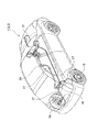
以下、本発明の第1の実施の形態を図面に基づいて説明する。図1及び図2は、第1実施形態に係る電動パーキングブレーキ装置全体の構成図であり、図1は電動パーキングブレーキ装置の車両設置状態を示し、図2は電動パーキングブレーキ装置の詳細構成を示している。
(First embodiment)
DESCRIPTION OF EXEMPLARY EMBODIMENTS Hereinafter, a first embodiment of the invention will be described with reference to the drawings. 1 and 2 are configuration diagrams of the entire electric parking brake device according to the first embodiment, FIG. 1 shows a vehicle installation state of the electric parking brake device, and FIG. 2 shows a detailed configuration of the electric parking brake device. ing.
図1及び図2に示すように、電動パーキングブレーキ装置1は、ECU(着座検出手段、制御手段)11、アクチュエータ13、イコライザ15、PKBケーブル17及びパーキングブレーキ19を備えている。また、電動パーキングブレーキ装置1は、電源部21、ヒューズ23、エマージェンシー解除操作部25、及び解除ケーブル27を具備している。さらに、電動パーキングブレーキ装置1は、インジケータランプ29、スピーカ(警告手段)30、各種センサ・スイッチ31〜59、メインハーネス61、コネクタ63及びボディハーネス65を有している。
As shown in FIGS. 1 and 2, the electric parking brake device 1 includes an ECU (sitting detection means, control means) 11, an
電動パーキングブレーキ装置1は、ECU11により制御されるアクチュエータ13がイコライザ15及びPKBケーブル17を介して、車両後輪側に設置されたパーキングブレーキ19を自動解除及び自動作動させるものである。
In the electric parking brake device 1, the
電動パーキングブレーキ装置1のECU11とアクチュエータ13とは、電源部21に接続されている。電源部21は、ヒューズ23を介してECU11とアクチュエータ13とからなるコントロールユニット10に電圧を供給するものであり、詳しくは電源部21の第1端子21aから第1ヒューズ23a介してECU11に電圧を供給し、第2端子21bから第2ヒューズ23b介してアクチュエータ13に電圧を供給する構成となっている。
The ECU 11 and the
エマージェンシー解除操作部25は、解除ケーブル27を介してアクチュエータ13に接続されており、手動にて操作されることにより早期にアクチュエータ13を作動させ、パーキングブレーキ19を解除させることが可能とされたものである。
The emergency
インジケータランプ29及び各種センサ・スイッチ31〜59は、メインハーネス61、コネクタ63及びボディハーネス65を介してECU11に接続されている。
The
ここで、インジケータランプ29は、パーキングブレーキ19の自動解除及び自動作動や、システム異常などの状態を表示するためのものであって、ECU11からの制御信号により点灯及び消灯する。
Here, the
スピーカ30は、ECU11から送信された制御信号に基づいて、所定の警告音を発生させる。これにより、スピーカ30は、所定の警告を行う。
The
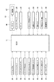
また、各種センサ・スイッチ31〜59それぞれは、検出結果又は入力内容に応じた信号をECU11に送信する構成となっている。図3は、第1実施形態に係る電動パーキングブレーキ装置1の一部構成図である。
Each of the
同図に示すように、各種センサ・スイッチ31〜59の1つであるパーキングスイッチ31は、パーキングブレーキの作動操作及び解除操作が可能となっている。具体的には、パーキングスイッチ31は、操作内容に応じた操作信号をECU11に送信する。なお、ECU11は、当該操作信号の内容に応じてアクチュエータ13を作動させることで、パーキングブレーキ19の電動による解除及び作動を行う。
As shown in the figure, a
また、イグニッションセンサ33は、イグニッションスイッチの状態を検出するものであり、イグニッションOFFの状態であるか、アクセサリONの状態であるか、エンジン作動状態であるかを検出し、検出した結果に関するイグニッション信号をECU11に送信する。また、イグニッションセンサ33は、車両キーが挿入されているか否かについても検出する構成とされており、検出した結果をイグニッション信号に含めてECU11に送信する。
The
アクセルポジションセンサ35は、アクセルペダルの操作を検出するためのものであって、具体的にはアクセルペダル部に設置されてアクセルペダルの動きに同期したアクセルポジション信号をECU11に送信する。
The
ブレーキペダルスイッチ(ブレーキ操作検出センサ)37は、ブレーキペダル部に設置され、ブレーキペダルの操作を検出する。具体的には、ブレーキペダルスイッチ37は、ブレーキペダル踏み込み操作(ブレーキペダルON)及びブレーキペダル戻し操作(ブレーキペダルOFF)を検出する。そして、ブレーキペダルスイッチ37は、検出した結果に関するブレーキペダル信号をECU11に送信する。
A brake pedal switch (brake operation detection sensor) 37 is installed in the brake pedal portion and detects the operation of the brake pedal. Specifically, the
クラッチポジションセンサ39は、クラッチペダルの操作を検出するためのものであって、アクセルポジションセンサ35と同様にクラッチペダルの動きに同期したクラッチポジション信号をECU11に送信する。
The
エンジン回転数検出センサ41は、エンジンの回転数を検出し、検出した結果に関するエンジン回転数信号をECU11に送信する。エンジントルク検出センサ43は、エンジントルクを検出し、検出した結果に関するエンジントルク信号をECU11に送信する。
The engine
シフトポジション検出センサ45は、シフトポジションの状態、すなわちドライブポジションであるか、ニュートラルポジションであるかなどを検出し、検出した結果に関するシフトポジション信号をECU11に送信する。
The shift
シート圧力センサ(着座検出手段)47は、運転席の座面に設置されており、運転席に加わる圧力を検出する。そして、シート圧力センサ47は、検出した結果に関する圧力信号をECU11に送信する。
The seat pressure sensor (seat detection means) 47 is installed on the seat surface of the driver's seat and detects the pressure applied to the driver's seat. Then, the
ライニング温度センサ51は、RRブレーキパッド又はライニング内部に設置されており、RRブレーキ摩擦材の温度を検出し、検出した結果に関する温度信号をECU11に送信する。
The
荷重センサ53は、アクチュエータ13の内部に設置されており、PKBケーブル17のアクチュエータ側の端部に加わる荷重を計測し、計測結果に関する荷重信号をECU11に送信するものである。
The
また、勾配センサ55は、車両が停車している路面の傾斜角を検出するものであり、検出した結果に関する傾斜角信号をECU11に送信する。
The
車輪速センサ57は、4輪のアクスルハウジング部位に設けられており、各車輪速を検出し、検出した結果に関する車輪速信号をECU11に送信する。
The
減速機回転センサ59は、アクチュエータ13の内部に設置され、アクチュエータ内のギヤ(後述する減速機67)の回転数を検出し、検出した結果に関する減速機回転数信号をECU11に送信する。
The reduction
ECU11は、上記各種センサ・スイッチ31〜59からの信号に基づいて、パーキングブレーキ19の自動解除及び自動作動するようになっており、自動解除及び自動作動する際には、アクチュエータ13を作動させるようになっている。
The ECU 11 automatically releases and automatically operates the
また、図3に示すように、アクチュエータ13は、モータMと減速機67とを備えている。次にアクチュエータ13を備えるコントロールユニット10について、図4を参照して説明する。
As shown in FIG. 3, the
図4は、電動パーキングブレーキ装置1のコントロールユニット10の内部構成図である。同図に示すように、コントロールユニット10は、ECU11及びアクチュエータ13がハウジング69に収納された構成となっている。具体的に説明すると、ECU11は、モータMに接続されており、モータMを正転駆動又は逆転駆動するようになっている。また、モータMは、減速機67に接続されている。減速機67は、駆動ギヤ71、ガイドシャフト73、第1従動ギヤ75、駆動シャフト77、及び第2従動ギヤ79からなっている。
FIG. 4 is an internal configuration diagram of the
駆動ギヤ71は、モータMに接続され、モータMからの回転力を、ガイドシャフト73により軸支される第1従動ギヤ75に伝える。また、第1従動ギヤ75は、駆動シャフト77により軸支される第2従動ギヤ79に接続され、自己の回転力を第2従動ギヤ79に伝達する。さらに、駆動シャフト77は、ねじ切り加工され、ねじ切り部と噛み合うように駆動ナット81が取り付けられている。このため、駆動ナット81は、第2従動ギヤ79が回転すると駆動シャフト77の延在方向に沿って移動する。また、駆動ナット81は、荷重センサ53(図示せず)を有するケーシング83に連結されている。このため、ケーシング83は、駆動ナット81の移動に合わせて駆動シャフト77の長手方向に移動可能となっている。
The
このように構成されるため、ECU11がモータMを正転駆動又は逆転駆動させると、第2従動ギヤ79の回転により駆動シャフト77が回転し、駆動ナット81の移動と共にケーシング83が移動してPKBケーブル17を引き込み又は繰り出しする。そして、この引き込み又は繰り出しによって、パーキングブレーキ19は解除又は作動することとなる。
With this configuration, when the
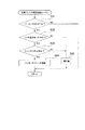
次に、電動パーキングブレーキ装置1の詳細動作を図5に示すフローチャートに沿って説明する。 Next, the detailed operation of the electric parking brake device 1 will be described with reference to the flowchart shown in FIG.
図5に示すステップST11にて、ECU11は、パーキングスイッチ31から送信された操作信号を読み込んで、パーキングスイッチ31でパーキングブレーキの解除操作が行われたかどうかを判断する。
In step ST <b> 11 shown in FIG. 5, the
この結果、ECU11は、パーキングブレーキの解除操作が行われたと判断した場合(ST11:YES)には、ステップST12に進み、パーキングブレーキの解除操作が行われていないと判断した場合(ST11:NO)には、ステップST11に戻る。
As a result, when it is determined that the parking brake release operation has been performed (ST11: YES), the
ステップST12にて、ECU11は、シート圧力センサ47から送信された圧力信号を読み込んで、当該圧力信号が示す圧力に運転席の座面の面積を乗じる。そして、ECU11は、これにより得られた乗算値と所定のしきい値とを比較する。
In step ST12, the
この結果、ECU11は、乗算値がしきい値を超えた場合(ステップST12:YES)にはステップST13に進み、乗算値がしきい値以下となる場合(ステップST12:NO)にはステップST11に戻る。
As a result, the
ステップST13にて、ECU11は、運転者が運転席に着座したと判断する。言い換えれば、ECU11は、運転者の着座を検出する。次いで、ECU11は、パーキングブレーキ19を解除する。その後、電動パーキングブレーキ装置1は、ステップST11に戻る。
In step ST13, the
ここで、しきい値は、例えば、32(kg)となる。ここで、32(kg)という値は、以下の式(1)により算出されるものである。 Here, the threshold value is, for example, 32 (kg). Here, the value 32 (kg) is calculated by the following equation (1).
36(kg)(日本人成人女性の1パーセンタイル値)−4(kg)(両足接地により運転席にかかる圧力が低下した分)=32(kg) …(1)
以上により、第1の実施の形態では、電動パーキングブレーキ装置1は、パーキングブレーキの解除操作がなされ、且つ、圧力センサ47及びECU11が運転者の着座を検出した場合にのみ、パーキングブレーキ19を解除する。即ち、電動パーキングブレーキ装置1は、運転者の着座を検出した場合にのみ、パーキングブレーキ19の解除を許可する。ここで、運転者は、通常、着座してからパーキングスイッチ31を操作するので、電動パーキングブレーキ装置1は、運転者の意図にしたがってパーキングブレーキ19を解除することが出来る。一方、運転者以外の乗員(例えば子供や犬)が誤ってパーキングスイッチでパーキングブレーキの解除操作をしても、電動パーキングブレーキ装置1はパーキングブレーキを解除しないので、運転者の意図しないパーキングブレーキの解除を防止することが出来る。
36 (kg) (1st percentile value for Japanese adult women) -4 (kg) (the amount of pressure applied to the driver's seat decreased by touching both feet) = 32 (kg) (1)
As described above, in the first embodiment, the electric parking brake device 1 releases the
また、従来の電動パーキングブレーキ装置として、ステアリングホイールと車両側面との間にパーキングスイッチを配置したものも知られている。当該従来の電動パーキングブレーキ装置では、運転者以外の乗員がパーキングスイッチを操作しづらくなっている。しかし、パーキングスイッチがステアリングホイールに対してシフトレバーの反対側に配置されるため、運転者が車両を発進させる際には、パーキングスイッチを押した後、一旦ステアリングホイールを持ち替えてシフトレバーを操作する必要があるので、運転操作に手間がかかっていた。したがって、当該従来の電動パーキングブレーキ装置には、運転操作に手間がかかるという問題点があった。 Further, as a conventional electric parking brake device, a parking switch disposed between a steering wheel and a vehicle side surface is also known. In the conventional electric parking brake device, it is difficult for passengers other than the driver to operate the parking switch. However, since the parking switch is disposed on the opposite side of the shift lever with respect to the steering wheel, when the driver starts the vehicle, after pushing the parking switch, the steering wheel is temporarily moved to operate the shift lever. Because it was necessary, it took time and effort to drive. Therefore, the conventional electric parking brake device has a problem that it takes time and effort to drive.
しかし、第1の実施の形態に係る電動パーキングブレーキ装置1では、パーキングスイッチ31を車両とステアリングホイールとの間に配置する必要がないので、このような問題点は生じない。また、電動パーキングブレーキ装置1では、どのような位置にパーキングスイッチ31を配置しても良いので、車室内のレイアウトの自由度が当該従来の電動パーキングブレーキ装置よりも高くなる。
However, in the electric parking brake device 1 according to the first embodiment, there is no need to arrange the
また、従来の電動パーキングブレーキ装置として、2段階操作式のパーキングスイッチを備えるものが知られている。当該従来の電動パーキングブレーキ装置においても、運転者以外の乗員がパーキングスイッチを操作しづらくなっている。しかし、運転者も同様にパーキングスイッチを操作しづらくなるので、当該従来の電動パーキングブレーキ装置では、運転操作に手間がかかるという問題点があった。 Further, a conventional electric parking brake device having a two-step operation type parking switch is known. Also in the conventional electric parking brake device, it is difficult for passengers other than the driver to operate the parking switch. However, since it is difficult for the driver to operate the parking switch in the same manner, the conventional electric parking brake device has a problem in that it takes time to perform the driving operation.
しかし、電動パーキングブレーキ装置1では、パーキングスイッチ31を2段階操作式とする必要がないので、このような問題点は生じない。
However, in the electric parking brake device 1, it is not necessary to set the
(第2の実施の形態)
次に、第2実施形態に係る電動パーキングブレーキ装置2について説明する。第2実施形態に係る電動パーキングブレーキ装置2は、電動パーキングブレーキ装置1とほぼ同様であるが、パーキングブレーキ19の自動作動処理の点において異なっている。以下、電動パーキングブレーキ装置2の詳細動作を図6に示すフローチャートに沿って説明する。
(Second Embodiment)
Next, the electric parking brake device 2 according to the second embodiment will be described. The electric parking brake device 2 according to the second embodiment is substantially the same as the electric parking brake device 1, but is different in terms of automatic operation processing of the
図6に示すステップST21にて、ECU11は、パーキングスイッチ31から送信された操作信号を読み込んで、パーキングスイッチ31でパーキングブレーキの解除操作が行われたかどうかを判断する。
In step ST <b> 21 shown in FIG. 6, the
この結果、ECU11は、パーキングブレーキの解除操作が行われたと判断した場合(ST21:YES)には、ステップST22に進み、パーキングブレーキの解除操作が行われていないと判断した場合(ST21:NO)には、ステップST21に戻る。
As a result, when it is determined that the parking brake release operation has been performed (ST21: YES), the
ステップST22にて、ECU11は、シート圧力センサ47から送信された圧力信号を読み込んで、当該圧力信号が示す圧力に運転席の座面の面積を乗じる。そして、ECU11は、これにより得られた乗算値と所定のしきい値とを比較する。
In step ST22, the
この結果、ECU11は、乗算値がしきい値を超えた場合(ステップST22:YES)にはステップST23に進み、乗算値がしきい値以下となる場合(ステップST22:NO)にはステップST21に戻る。
As a result, the
ステップST23にて、ECU11は、運転者が運転席に着座したと判断する。言い換えれば、ECU11は、運転者の着座を検出する。次いで、ECU11は、ブレーキペダルスイッチ37から出力されたブレーキペダル信号を読み込んで、ブレーキペダル信号がブレーキペダルの踏み込み操作を示すかどうか、言い換えれば、ブレーキペダルスイッチ37がブレーキペダルの踏み込み操作を検出したかどうかを判断する。
In step ST23, the
この結果、ECU11は、ブレーキペダルスイッチ37がブレーキペダルの踏み込み操作を検出したと判断した場合(ST23:YES)には、ステップST24に進み、ブレーキペダルスイッチ37がブレーキペダルの踏み込み操作を検出していないと判断した場合(ST23:NO)には、ステップST21に戻る。
As a result, if the
ステップST24にて、ECU11は、パーキングブレーキ19を解除する。その後、電動パーキングブレーキ装置2は、ステップST21に戻る。
In step ST24, the
以上により、第2の実施の形態では、電動パーキングブレーキ装置2は、シート圧力センサ47及びECU11が運転者の着座を検出し、且つ、ブレーキペダルスイッチ37がブレーキペダルの踏み込み操作を検出した場合にのみ、パーキングブレーキ19を解除する。ここで、運転者は、通常、着座し、且つブレーキペダルを踏み込んだ状態でパーキングスイッチ31を操作するので、電動パーキングブレーキ装置2は、電動パーキングブレーキ装置1よりも運転者の意図に確実にしたがってパーキングブレーキ19を解除することが出来る。また、電動パーキングブレーキ装置2は、運転者以外の乗員によるパーキングブレーキ19の解除を電動パーキングブレーキ装置1よりも確実に防止することが出来るので、運転者の意図しないパーキングブレーキ19の解除を電動パーキングブレーキ装置1よりも確実に防止することが出来る。
As described above, in the second embodiment, in the electric parking brake device 2, the
(第3の実施の形態)
次に、第3実施形態に係る電動パーキングブレーキ装置3について説明する。第3実施形態に係る電動パーキングブレーキ装置3は、電動パーキングブレーキ装置1とほぼ同様であるが、パーキングブレーキ19の自動作動処理の点において主に異なっている。以下、電動パーキングブレーキ装置3の詳細動作を図7に示すフローチャートに沿って説明する。
(Third embodiment)
Next, the electric parking brake device 3 according to the third embodiment will be described. The electric parking brake device 3 according to the third embodiment is substantially the same as the electric parking brake device 1, but mainly differs in terms of automatic operation processing of the
図7に示すステップST31にて、ECU11は、パーキングスイッチ31から送信された操作信号を読み込んで、パーキングスイッチ31でパーキングブレーキの解除操作が行われたかどうかを判断する。
In step ST31 shown in FIG. 7, the
この結果、ECU11は、パーキングブレーキの解除操作が行われたと判断した場合(ST31:YES)には、ステップST32に進み、パーキングブレーキの解除操作が行われていないと判断した場合(ST31:NO)には、ステップST31に戻る。
As a result, when it is determined that the parking brake release operation has been performed (ST31: YES), the
ステップST32にて、ECU11は、シート圧力センサ47から送信された圧力信号を読み込んで、当該圧力信号が示す圧力に運転席の座面の面積を乗じる。そして、ECU11は、これにより得られた乗算値と所定のしきい値とを比較する。
In step ST32, the
この結果、ECU11は、乗算値がしきい値を超えた場合(ST32:YES)にはステップST33に進み、乗算値がしきい値以下となる場合(ST32:NO)にはステップST35に進む。
As a result, the
ステップST33にて、ECU11は、運転者が運転席に着座したと判断する。言い換えれば、ECU11は、運転者の着座を検出する。次いで、ECU11は、ブレーキペダルスイッチ37から出力されたブレーキペダル信号を読み込んで、ブレーキペダル信号がブレーキペダルの踏み込み操作を示すかどうか、言い換えれば、ブレーキペダルスイッチ37がブレーキペダルの踏み込み操作を検出したかどうかを判断する。
In step ST33, the
この結果、ECU11は、ブレーキペダルスイッチ37がブレーキペダルの踏み込み操作を検出したと判断した場合(ST33:YES)には、ステップST34に進み、ブレーキペダルスイッチ37がブレーキペダルの踏み込み操作を検出していないと判断した場合(ST33:NO)には、ステップST35に進む。
As a result, when the
ステップST34にて、ECU11は、パーキングブレーキ19を解除する。その後、電動パーキングブレーキ装置3は、ステップST31に戻る。
In step ST34, the
ステップST35にて、ECU11は、所定の警告音を発生させる旨の制御信号をスピーカ30に出力し、スピーカ30は、当該制御信号に基づいて、所定の警告音を発生させる。その後、電動パーキングブレーキ装置3は、ステップST31に戻る。ここで、警告音の内容は、例えば、「パーキングブレーキの解除は出来ません」となる。
In step ST35, the
以上により、第3の実施の形態では、電動パーキングブレーキ装置3は、パーキングブレーキ19の解除を禁止する際にパーキングスイッチ31で解除操作が行われた場合には、所定の警告音を発生させる。
As described above, in the third embodiment, the electric parking brake device 3 generates a predetermined warning sound when the release operation is performed with the
したがって、電動パーキングブレーキ装置3は、運転者の意図しないパーキングスイッチ31の操作を防止することが出来るので、運転者の意図しないパーキングブレーキ19の解除を電動パーキングブレーキ装置1、2よりも確実に防止することが出来る。
Therefore, since the electric parking brake device 3 can prevent the operation of the
以上、実施形態に基づき本発明を説明したが、本発明は上記実施形態に限られるものではなく、各実施形態を組み合わせてもよいし、本発明の趣旨を逸脱しない範囲で、変更を加えてもよい。例えば、第1〜第3の実施の形態では、スピーカ30が警告音を発生させることで警告を行うこととしたが、警告の内容を画面表示することで警告を行うようにしても良い。
As mentioned above, although this invention was demonstrated based on embodiment, this invention is not restricted to the said embodiment, Each embodiment may be combined and it adds in the range which does not deviate from the meaning of this invention. Also good. For example, in the first to third embodiments, the
1〜3…電動パーキングブレーキ装置
10…コントロールユニット
11…ECU(着座検出手段、制御手段)
30…スピーカ(警告手段)
31…パーキングスイッチ
37…ブレーキペダルスイッチ(ブレーキ操作検出センサ)
1-3. Electric
30 ... Speaker (Warning means)
31 ...
Claims (3)
運転者の着座を検出する着座検出手段と、
前記着座検出手段が前記運転者の着座を検出した場合にのみ、前記パーキングブレーキの解除を許可する制御手段と、
を備えることを特徴とする電動パーキングブレーキ装置。 In the electric parking brake device that automatically operates the parking brake of the vehicle,
Seating detection means for detecting the driver's seating;
Control means for permitting release of the parking brake only when the seating detection means detects the driver's seating;
An electric parking brake device comprising:
前記制御手段は、前記ブレーキ操作検出センサが前記ブレーキペダルの踏み込み操作を検出した場合にのみ、前記パーキングブレーキの解除を許可することを特徴とする請求項1に記載の電動パーキングブレーキ装置。 It has a brake operation detection sensor that detects the operation of the brake pedal,
2. The electric parking brake device according to claim 1, wherein the control unit permits the release of the parking brake only when the brake operation detection sensor detects a depression operation of the brake pedal.
パーキングブレーキの解除操作が可能なパーキングスイッチと、を備え、
前記制御手段は、前記パーキングブレーキの解除を許可する際に前記パーキングスイッチで前記パーキングブレーキの解除操作が行われた場合には、前記パーキングブレーキを解除する一方、前記パーキングブレーキの解除を禁止する際に前記パーキングスイッチで前記パーキングブレーキの解除操作が行われた場合には、前記警告手段に前記警告を行わせることを特徴とする請求項1または2に記載の電動パーキングブレーキ装置。 Warning means for giving a predetermined warning;
A parking switch capable of releasing the parking brake,
The control means releases the parking brake and prohibits the release of the parking brake when the parking brake is released by the parking switch when permitting the release of the parking brake. 3. The electric parking brake device according to claim 1, wherein when the parking brake is released by the parking switch, the warning unit causes the warning to be performed. 4.
Priority Applications (1)
| Application Number | Priority Date | Filing Date | Title |
|---|---|---|---|
| JP2004062367A JP2005247194A (en) | 2004-03-05 | 2004-03-05 | Electric parking brake device |
Applications Claiming Priority (1)
| Application Number | Priority Date | Filing Date | Title |
|---|---|---|---|
| JP2004062367A JP2005247194A (en) | 2004-03-05 | 2004-03-05 | Electric parking brake device |
Publications (1)
| Publication Number | Publication Date |
|---|---|
| JP2005247194A true JP2005247194A (en) | 2005-09-15 |
Family
ID=35028099
Family Applications (1)
| Application Number | Title | Priority Date | Filing Date |
|---|---|---|---|
| JP2004062367A Pending JP2005247194A (en) | 2004-03-05 | 2004-03-05 | Electric parking brake device |
Country Status (1)
| Country | Link |
|---|---|
| JP (1) | JP2005247194A (en) |
Cited By (2)
| Publication number | Priority date | Publication date | Assignee | Title |
|---|---|---|---|---|
| JP5263413B2 (en) * | 2010-01-29 | 2013-08-14 | トヨタ自動車株式会社 | Parking control system |
| CN108501925A (en) * | 2018-04-16 | 2018-09-07 | 江铃控股有限公司 | Electronic brake system voluntarily discharges the control method and system of parking |
-
2004
- 2004-03-05 JP JP2004062367A patent/JP2005247194A/en active Pending
Cited By (2)
| Publication number | Priority date | Publication date | Assignee | Title |
|---|---|---|---|---|
| JP5263413B2 (en) * | 2010-01-29 | 2013-08-14 | トヨタ自動車株式会社 | Parking control system |
| CN108501925A (en) * | 2018-04-16 | 2018-09-07 | 江铃控股有限公司 | Electronic brake system voluntarily discharges the control method and system of parking |
Similar Documents
| Publication | Publication Date | Title |
|---|---|---|
| JP5234304B2 (en) | Electric parking brake control system and control method for automobile | |
| JP4179388B1 (en) | Vehicle control device | |
| JP5895907B2 (en) | Vehicle shift control device | |
| JP2007170546A (en) | Vehicle control system | |
| US11198420B2 (en) | System and method for operating a motor vehicle with an electric parking brake | |
| KR20180056836A (en) | Method for controlling auto hold of vehicle brake | |
| JP4147253B2 (en) | Electric parking brake control device | |
| JP7311088B2 (en) | electric parking brake device | |
| JP2005247194A (en) | Electric parking brake device | |
| JP4415706B2 (en) | Electric parking brake device | |
| JP7420097B2 (en) | Vehicle control device and vehicle | |
| RU2711883C1 (en) | Electric parking brake device | |
| JP4164096B2 (en) | Vehicle control system | |
| JP2005255103A (en) | Motor-driven parking brake device | |
| JP2005271887A (en) | Electric parking brake device | |
| JPH07215196A (en) | On-slope starting auxiliary device/using traction control system | |
| JP2005254997A (en) | Motor-driven parking brake device | |
| JP2005263025A (en) | Electric parking brake device | |
| JP2007198238A (en) | Vehicle control system | |
| KR20070034755A (en) | Method and apparatus for preventing vehicle departure from automatic transmission vehicle | |
| JP2005255102A (en) | Motor-driven parking brake device | |
| JP4646659B2 (en) | Parking brake assist device | |
| JP4492197B2 (en) | Automatic release parking brake device | |
| JP4811382B2 (en) | Parking brake device | |
| JP5200383B2 (en) | Electric parking brake device for vehicle and abnormality detection method for electric parking brake device for vehicle |