JP2005244227A - Two-dimensional scanning mechanism of wafer - Google Patents
Two-dimensional scanning mechanism of wafer Download PDFInfo
- Publication number
- JP2005244227A JP2005244227A JP2005045898A JP2005045898A JP2005244227A JP 2005244227 A JP2005244227 A JP 2005244227A JP 2005045898 A JP2005045898 A JP 2005045898A JP 2005045898 A JP2005045898 A JP 2005045898A JP 2005244227 A JP2005244227 A JP 2005244227A
- Authority
- JP
- Japan
- Prior art keywords
- link
- end effector
- scanning device
- joint
- operable
- Prior art date
- Legal status (The legal status is an assumption and is not a legal conclusion. Google has not performed a legal analysis and makes no representation as to the accuracy of the status listed.)
- Withdrawn
Links
Images
Classifications
-
- H—ELECTRICITY
- H01—ELECTRIC ELEMENTS
- H01J—ELECTRIC DISCHARGE TUBES OR DISCHARGE LAMPS
- H01J37/00—Discharge tubes with provision for introducing objects or material to be exposed to the discharge, e.g. for the purpose of examination or processing thereof
- H01J37/30—Electron-beam or ion-beam tubes for localised treatment of objects
- H01J37/317—Electron-beam or ion-beam tubes for localised treatment of objects for changing properties of the objects or for applying thin layers thereon, e.g. for ion implantation
- H01J37/3171—Electron-beam or ion-beam tubes for localised treatment of objects for changing properties of the objects or for applying thin layers thereon, e.g. for ion implantation for ion implantation
-
- H—ELECTRICITY
- H01—ELECTRIC ELEMENTS
- H01J—ELECTRIC DISCHARGE TUBES OR DISCHARGE LAMPS
- H01J2237/00—Discharge tubes exposing object to beam, e.g. for analysis treatment, etching, imaging
- H01J2237/20—Positioning, supporting, modifying or maintaining the physical state of objects being observed or treated
- H01J2237/202—Movement
- H01J2237/20221—Translation
- H01J2237/20228—Mechanical X-Y scanning
Landscapes
- Chemical & Material Sciences (AREA)
- Analytical Chemistry (AREA)
- Container, Conveyance, Adherence, Positioning, Of Wafer (AREA)
Abstract
Description
本発明は、一般的に半導体の処理システムに関するものであり、特に、イオン注入の間、基板の質の高い、正確な移動のための装置及び方法に関するものである。 The present invention relates generally to semiconductor processing systems, and more particularly to an apparatus and method for high quality, accurate movement of a substrate during ion implantation.
半導体産業において、基板(例 半導体基板)上にいろいろな処理を達成するために、種々の製造工程が定型的に基板上に実行される。例えば、イオン注入のような工程は、特殊なタイプのイオンを注入することによって、基板上に誘電体層の拡散率を制限するように、基板の内外に粒子の特性を得るために実行される。従来、イオン注入は、バッチ処理(多数の基板が同時に処理される)、あるいは連続処理(基板が1枚ずつ個別に処理される)のどちらかで実行される。例えば、従来の高エネルギーあるいは高電流バッチイオン注入機は、ショートイオンビームをなし得るように操作され、そこでは、多くのウエハが回転盤あるいはディスク上に配置されており、また、回転盤は回転され、同時にイオンビーム中に径方向に移動され、その処理中、全ての基板の表面領域を何回もビームに曝すことになる。しかし、このような基板のバッチ処理は、次第にイオン注入機のサイズを実質的に大きくしている。 In the semiconductor industry, various manufacturing processes are routinely performed on a substrate in order to achieve various processes on the substrate (eg, a semiconductor substrate). For example, processes such as ion implantation are performed to obtain particle characteristics inside and outside the substrate so as to limit the diffusivity of the dielectric layer on the substrate by implanting special types of ions. . Conventionally, ion implantation is performed in either a batch process (a number of substrates are processed simultaneously) or a continuous process (a substrate is processed individually one by one). For example, conventional high energy or high current batch ion implanters are operated to produce a short ion beam, where many wafers are placed on a rotating disk or disk, and the rotating disk rotates. At the same time, it is moved radially into the ion beam, exposing the surface area of all substrates to the beam many times during the process. However, such batch processing of substrates gradually increases the size of the ion implanter.
他方、典型的な連続処理では、イオンビームを静止したウエハを横断するように単一のビームでスキャンするか、あるいはウエハが、扇形にあるいはスキャンされるビーム中を一方向に移動される。しかし、一様なイオンビームをスキャンするあるいは形成する工程は、概して、複雑な及び/あるいは長いビームラインが要求され、概して低エネルギーでは望ましくない。さらに、一様な移動及び/あるいはイオンビームあるいはウエハの回転は、概して、イオン注入が一様にウエハを横断するように行われることを要求する。しかし、そのような一様な移動及び/あるいは回転は、従来の装置の移動及び工程中のスキャン機構と関連して、少なくとも部分的に、実質的な初期力(inertial force)により得ることは困難である。
それ故、基板を横断するイオンビームをスキャンするための装置、そして、基板がイオンビームに関して、一様に移動し及び/あるいは回転されるものが、必要とされている。
On the other hand, in a typical continuous process, the ion beam is scanned with a single beam across a stationary wafer, or the wafer is moved in one direction in a fan or scanned beam. However, the process of scanning or forming a uniform ion beam generally requires complex and / or long beam lines and is generally not desirable at low energy. In addition, uniform movement and / or ion beam or wafer rotation generally requires that ion implantation be performed across the wafer uniformly. However, such uniform movement and / or rotation is difficult to obtain, at least in part, due to substantial inertial forces, in conjunction with conventional device movement and in-process scanning mechanisms. It is.
Therefore, there is a need for an apparatus for scanning an ion beam across a substrate and one in which the substrate is moved and / or rotated uniformly with respect to the ion beam.
本発明は、従来技術の上記限界を克服するものである。 The present invention overcomes the above limitations of the prior art.
したがって、以下に本発明のいくつかの観点の基本的な理解をするために、本発明の要約を述べる。この要約は、本発明の広範囲の全体像ではない。本発明の鍵あるいは重大な要素を認識するものでもないし、あるいは発明の概略を詳細に述べるものでもない。その目的は、前置きとして単純な形式で、本発明のある概念を示すことにあり、詳細は後述される。
本発明は、概して基板を処理するためのスキャニング機構に関するものであり、さらにスキャニング機構は2‐リンク回転サブシステムを含む。本発明の一実施形態によれば、基部が備えられ、第1リンクが第1ジョイントによって基部に回転自在に結合され、そして、第1リンクは第1ジョイントと協働する第1軸の周囲に、第1の回転方向に回転するように作動可能である。さらに、第2リンクは、第1ジョイントから所定距離、間隔をおく第2ジョイントによって、第1リンクに回転自在に結合され、さらに第2リンクは第2ジョイントと協働する第2軸の周囲に、第2の回転方向に回転するように作動可能である。さらに、第2リンクはエンドエフェクタを含み、エンドエフェクタはさらに、第2ジョイントから所定距離、間隔がある。
Accordingly, the following is a summary of the invention in order to provide a basic understanding of some aspects of the invention. This summary is not an extensive overview of the invention. It is not intended to recognize the key or critical elements of the invention or to delineate the invention in detail. Its purpose is to present some concepts of the invention in a simplified form as a prelude and will be described in detail below.
The present invention generally relates to a scanning mechanism for processing a substrate, and the scanning mechanism further includes a two-link rotating subsystem. According to an embodiment of the present invention, a base is provided, a first link is rotatably coupled to the base by a first joint, and the first link is around a first axis that cooperates with the first joint. , Operable to rotate in a first rotational direction. Further, the second link is rotatably coupled to the first link by a second joint spaced a predetermined distance from the first joint, and the second link is disposed around a second axis that cooperates with the second joint. And is operable to rotate in a second rotational direction. Further, the second link includes an end effector, and the end effector is further spaced a predetermined distance from the second joint.
本発明の他の実施形態によれば、第1及び第2アクチュエータが備えられ、そこで第1及び第2アアクチュエータは、それぞれ第1軸及び第2軸の周囲で第1リンクおよび第2リンクをそれぞれ回転させるように作動可能である。例えば、第1アクチュエータは、第1の回転方向に第1リンクを連続的に回転するように作動可能であり、第2アクチュエータは、第2の回転方向に第2リンクを連続的に回転するように作動可能である。一実施形態によれば、第1の回転方向と第2の回転方向は、互いに反対方向であり、そこでエンドエフェクタは、通常、直線の第1スキャンパスにおいて往復するように作動可能である。他の実施形態によれば、上記エンドエフェクタは、さらに第3ジョイントを経由して第2リンクに結合され、そこで上記エンドエフェクタは第2リンクに関して、回転及び/又は傾くように作動可能である。 According to another embodiment of the present invention, first and second actuators are provided, wherein the first and second actuators are connected to the first link and the second link around the first axis and the second axis, respectively. Each is operable to rotate. For example, the first actuator is operable to continuously rotate the first link in the first rotational direction, and the second actuator is configured to continuously rotate the second link in the second rotational direction. Can be operated. According to one embodiment, the first direction of rotation and the second direction of rotation are opposite to each other, where the end effector is typically operable to reciprocate in a linear first scan path. According to another embodiment, the end effector is further coupled to the second link via a third joint, where the end effector is operable to rotate and / or tilt with respect to the second link.
本発明のさらに他の実施形態によれば、第1リンク及び第2リンクは、略等しい長さであり、そこで第1スキャンパスに沿う連続的往復運動(移動)が通常、可能とされ、また、第1及び第2ジョイントは、それぞれ1方向で回転する。本発明のさらに他の実施形態によれば、エンドエフェクタの通常の一定速度は、第1スキャンパスに沿う所定の運動範囲内で維持することができ、そこで第1リンク及び第2リンクのそれぞれの回転速度は制御され、また、回転速度はエンドエフェクタの移動中、非ゼロ値(non-zero values)で維持される。 According to yet another embodiment of the present invention, the first link and the second link are of approximately equal length, where continuous reciprocation (movement) along the first scan path is typically allowed, and Each of the first and second joints rotates in one direction. According to yet another embodiment of the present invention, the normal constant velocity of the end effector can be maintained within a predetermined range of motion along the first scan path, wherein each of the first link and the second link. The rotational speed is controlled and the rotational speed is maintained at non-zero values during movement of the end effector.
さらに他の実施形態によれば、移動機構がさらに備えられ、そこで、基部と関係する回転サブシステムは、通常、スロースキャン軸と言われる第2スキャンパスに沿ってさらに作動可能であり、そこで第2スキャンパスは、通常、第1スキャンパスに対して垂直である。 According to yet another embodiment, a moving mechanism is further provided, wherein the rotation subsystem associated with the base is further operable along a second scan path, usually referred to as the slow scan axis, where the first The two scan path is usually perpendicular to the first scan path.
本発明の他の実施形態によれば、スキャニングシステムが備えられ、そこでコントローラが第1リンク及び第2リンクのそれぞれの回転速度を制御するように作動可能であり、その結果、所定範囲での基板の移動が、実質的に一定値で維持される。また、基板のスキャンニング提供され、その方法は所定範囲内で第1リンクおよび第2リンクを回転させることを含み、また、基板は、通常、一定速度で第1スキャンパスに沿って、所定範囲内で移動される。さらに、上記方法は、第1リンクおよび第2リンクのそれぞれの回転速度を維持することを含み、その結果、回転速度はゼロとなることはない。 According to another embodiment of the present invention, a scanning system is provided, wherein the controller is operable to control the respective rotational speeds of the first link and the second link, so that the substrate in a predetermined range. Movement is maintained at a substantially constant value. Also provided is scanning of the substrate, the method includes rotating the first link and the second link within a predetermined range, and the substrate is usually at a constant speed along the first scan path along the predetermined range. Moved within. Further, the method includes maintaining the respective rotation speeds of the first link and the second link, so that the rotation speed does not become zero.
前記及び関連する目的を達成するために、本発明は以下に記載され、特に特許請求の範囲に示された特徴からなる。以下の記述及び添付の図面は、本発明の実施形態を正確に述べている。しかし、これらの実施形態は、本発明の原理が実施される多くの方法のいくつかを示しているにすぎない。本発明の他の目的、利点、新しい特徴は、図面とともに考慮されれば、本発明の以下の詳細な記述から明らかになるであろう To the accomplishment of the foregoing and related ends, the invention comprises the features described below, and particularly pointed out in the claims. The following description and the annexed drawings set forth precisely embodiments of the invention. However, these embodiments are merely illustrative of some of the many ways in which the principles of the invention may be implemented. Other objects, advantages and novel features of the invention will become apparent from the following detailed description of the invention when considered in conjunction with the drawings.
本発明は、概してビームに関して基板を移動するスキャニング機構に関するものである。
特に、スキャニング機構は、基板によって見られる初期力の量を制限し、そこで、スキャニング機構の移動は、2‐リンク回転サブシステムを経由して往復する。そこで、図面を参照して説明すれば、全体として参照番号が、要素を指示するために使用される。これら観点の記述は単に例示的なものであって、本義を制限するものではない。以下の説明で、説明の目的としての、多くの特殊な詳細は、本発明の完全な理解のために示されたものである。しかしながら、本発明はこれら特殊な詳細がなくても実施できることは、当業者に明らかである。
The present invention relates generally to a scanning mechanism for moving a substrate with respect to a beam.
In particular, the scanning mechanism limits the amount of initial force seen by the substrate, where movement of the scanning mechanism reciprocates via the 2-link rotation subsystem. Thus, as described with reference to the drawings, reference numerals as a whole are used to indicate elements. The descriptions of these aspects are merely exemplary and do not limit the meaning. In the following description, for the purposes of explanation, numerous specific details are set forth in order to provide a thorough understanding of the present invention. However, it will be apparent to those skilled in the art that the present invention may be practiced without these specific details.
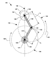
図を参照すると、図1は、本発明の一実施形態による、例示的なスキャニング機構100を説明するものである。例えばスキャニング機構100は、後述されるように、イオン注入工程に使用される(図示されない)イオンビームと関連して設けられるものである。本発明は多くの半導体処理システムと結合して使用され、全てのそのようなシステムは、本発明の範囲内に含まれるものと企図されていることに注意されるべきである。スキャニング機構100は、例えば、回転サブシステム110に、作動可能に結合される基部105を含んでいる。基部105は、例えば、ビーム(図示されない)に関して静止していてよく、あるいはさらに後述のように、ビームに関して移動するように作動可能であってもよい。これらと関連して、回転サブシステム110は、第1リンク115および第2リンク120を含んでおり、例えば、回転サブシステムは、第1リンク及び第2リンクの所定の移動を経由して、基部105に関して(図示されない)基板の直線移動を可能にする。
Referring to the figures, FIG. 1 illustrates an
一実施形態によれば、第1リンク115は、第1ジョイント125を経由して基部105に回転可能に連結される。上記第1リンクは第1回転方向128で、第1軸127の周囲に連続的に回転するように作動可能である(上記第1リンクは、上記第1ジョイントに関して、時計方向あるいは反時計方向に回転するように作動可能である)。第2リンク120は、さらに、第2ジョイント130を経由して第1リンク115に回転可能に連結され、上記第2ジョイントは第1ジョイント125から所定距離L離れている。上記第2リンクは、さらに第2回転方向133で、第2軸132の周囲に連続的に回転するように作動可能である(上記第2リンクは、上記第2ジョイントに関して、時計方向あるいは反時計方向に回転するように作動可能である)。第1リンク115および第2リンク120は、例えば、さらに独立して、第1及び第2の平面(図示されない)に平行して回転するようにそれぞれ作動可能であり、上記第1及び第2の平面は、第1軸127および第2軸132に関して、通常、垂直である。さらに、第1リンク115および第2リンク120は、それぞれ第1ジョイント125、第2ジョイント130の周囲で、それぞれ第1回転パス134、第2回転パス135に関して、連続的に360度回転するように作動可能である。
According to one embodiment, the
本発明の一実施形態によれば、第1の回転方向128は、第2の回転方向133と、通常、反対であり、そして、第2リンク120と関連するエンドエフェクタ140は、第1リンク115及び第2リンクの所定の移動と関連する第1スキャンパス142に沿って、直線移動するように作動可能である。例えば、エンドエフェクタ140は、上記第2リンクと関連する第3ジョイント145を経由して、第2リンク120に回転可能に連結され、そして、上記第3ジョイントは第2ジョイント130から所定距離L離れている。例えば、第3ジョイント145は、第3軸148の周囲でエンドエフェクタ140が回転147をするように作動可能である。さらに、他の実施形態によれば、第3ジョイント145は、エンドエフェクタ140を傾かせる(図示されない)ように作動可能であり、そして、一例では、上記エンドエフェクタは、(図示されない)第2平面に通常、平行である1以上の軸(図示されない)の周囲に、傾くように作動可能である。
According to one embodiment of the present invention, the first
例えば、エンドエフェクタ140は、さらに(図示されない)基板を固定することが可能であり、そして、通常、上記エンドエフェクタの移動は、上記基板の移動を規定する。例えば、エンドエフェクタ140は、静電チャック(ESC)を含んでもよく、上記ESCは上記エンドエフェクタに関して実質的に基板をつかみ、あるいは基板の位置を維持するように作動可能である。ESCは上記エンドエフェクタ140の一例として記載され、上記エンドエフェクタは有効搭載量(例えば、基板)のグリップを維持する種々の他の装置を含んでよく、そして、そのような全ての装置が本発明の範囲に含まれることが企図されることが、注意されるべきである。
For example, the
例えば、第1リンク115及び第2リンク120の所定の移動は、第1スキャンパス142に沿ってエンドエフェクタ140を直線状に往復(線形往復運動)させるために、さらに制御され得る。そして、(図示されない)基板は、イオンビーム(例えば、第1軸127と一致するイオンビーム)に関して所定の方法で移動できる。例えば、第3ジョイント145の回転は、さらに制御可能であり、そして、エンドエフェクタ140は、第1スキャンパス142と一定の回転関係を維持することが可能である。上記第2ジョイント及び第3ジョイント145間ばかりでなく、第1ジョイント125及び第2ジョイント130間の所定距離Lは、各ジョイント間で測定される時、リンク長が、通常、一致するように、注意されるべきである。例えば、第1リンク115と第2リンク120の長さの一致は、通常、後述されるような種々の運動学的(kinematic)利点がある。
For example, the predetermined movement of the
図2A乃至2Lは、本発明の他の実施形態による、回転サブシステムの種々の連続する位置を説明するものである。第1回転方向128及び第2回転方向133は、通常、一定であり、第1リンク115および第2リンク120の所定移動中、逆転しない。例えば、図2Aにおいて、エンドエフェクタ140は、第1スキャンパス142に沿って第1位置150にあり、第3ジョイント145は第1ジョイント125から所定距離Lの約2倍離れていて、エンドエフェクタの最大位置155を決めている。図2B乃至2Lのように、第1回転方向128及び第2回転方向133それぞれで、第1及び第2ジョイント125、130それぞれの周囲で、第1リンク115および第2リンク120が回転すると、エンドエフェクタ140は、第1スキャンパス142に沿って一直線状に移動できる。
2A-2L illustrate various successive positions of a rotating subsystem according to another embodiment of the present invention. The
例えば図2Gにおいて、エンドエフェクタ140は、第1スキャンパス142に沿って他の最大位置にあり、第3ジョイント145は、再び第1ジョイント125から所定距離Lの約2倍の距離離れている。例えば図2Hにおいて、第1回転方向128及び第2回転方向133が不変であるので、エンドエフェクタ140は、第1位置150の方へ戻りつつあるということに注意すべきである。一定の回転方向128及び133を維持している間、図2Lに示す位置にしたがって、回転サブシステム110は図2Aの最初の位置150へ戻るように作動可能であり、直線状往復を続けることができる。
For example, in FIG. 2G, the
第1リンク115、第2リンク120それぞれの回転方向128、133を一定に維持することは、通常、直線状の第1スキャンパス142に沿うエンドエフェクタ140の移動と関連して、多くの機械的及び運動学的利点を生ずる。例えば、エンドエフェクタ140の往復中、エンドエフェクタ140の実質的に一定の速度は、概してその運動の所定範囲内で望ましいことである。
Maintaining a constant
図3は図2A−2Lの種々の位置において、回転サブシステム110を説明しており、基板165(像として示されている)は、エンドエフェクタ140上にある。回転サブシステム110は、正しい縮尺で描かれておらず、エンドエフェクタ140は明らかな目的で基板より実質的に小さく描かれていることに注意されるべきである。具体的にエンドエフェクタ140は、略、基板165の大きさとすることが可能であり、適切な基板の支持体が設けられる。しかし、エンドエフェクタ140及び描かれた他の特徴は、いろいろな形状や大きさとすることが可能であり、そのような形状や大きさは、本発明の範囲に含まれることが理解されねばならない。
FIG. 3 illustrates the
図3に示すように、スキャニングシステム100は、エンドエフェクタ140の最大位置155と160の間で、第1スキャンパス142に沿って基板165を直線状に往復させるように作動可能である。それ故、基板165の反対端167まで移動する最大スキャン距離166は、スキャンパス142に沿って、通常、決めることができ(例 第1スキャンパスに沿う基板の周辺の反対端)、そして最大スキャン距離は、エンドエフェクタ140の最大位置155、160と関連している。本発明の一実施形態によれば、最大スキャン距離166は、基板165の径Dの2倍より大きい。最大スキャン距離166は径Dの2倍より大きいという量は、オーバーシュート167として限界を定められる。例えば、図2Fと2Hの間の位置にある図2Gに説明される位置のように、第1スキャンパス142に沿う基板165の往復で方向を変える時、オーバーシュート167は、有利に使用される。
As shown in FIG. 3, the
回転方向128、133が一定(例 不変)である間、エンドエフェクタ140及び基板165の移動は第1スキャンパス142に沿って往復し、最大位置155、160で方向を変えるということに注意されるべきである。そのようなエンドエフェクタ140(よって、基板165)の方向の変化は、エンドエフェクタ及び基板の、速度及び加速度の変化と関連する。イオン注入工程において、例えば、第1軸127と一致するような(図示されない)イオンビーム中を、基板165が通過する時、エンドエフェクタ140が第1スキャンパス142に沿って実質的に一定速度を維持することが通常、望まれる。そのような一定速度は、基板165がイオンビーム中を移動する際に、イオンビームに均一に曝されることになる。
しかしながら、第3ジョイント145(例 上記エフェクタ及び基板165と関連する)は、直線移動で最大位置155、160に近づく時のように、エンドエフェクタ140の往復移動により、エンドエフェクタの加速及び減速は避けられない。そのような最大位置155、160(例 スキャンパスの折り返し)近くでの加速度及び減速度は、初期力(イナーシャルフォース)及び関連するスキャニング機構100の基部105に伝達される反力を最小にするために、適切なレベルに維持されねばならない。基板165をイオンビームにさらしている間、エンドエフェクタ140の速度の変化により、例えば、基板を横切る一様でないイオン注入を導くことができる。
Note that the movement of the
However, the third joint 145 (eg, associated with the effector and
それ故、通常、イオンビーム中で基板を所定範囲で移動させるのに、一定速度が望ましい。例えば、エンドエフェクタの加速度及び減速度は、オーバーシュート167内に適応させることができるように、所定範囲168は、基板の物理的大きさ(例 基板の径の2倍)と関係する。したがって、一度、基板165がイオンビーム中を完全に通過すると、エンドエフェクタ140の加速度及び減速度は、実質的にイオン注入工程に影響しないか、あるいは、基板を横断して一様に照射しない。
Therefore, a constant speed is usually desirable for moving the substrate in a predetermined range in the ion beam. For example, the
図4は、本発明の他の実施形態を示し、スキャニング機構100の基部105は、さらに1以上の方向に移動するように作動可能である。例えば基部105は、移動機構170に作動可能に連結されており、そして、上記移動機構は第2スキャンパスに沿って、基部及び回転サブシステムを移動させるように作動可能であり、上記第2スキャンパスは実質的に第1スキャンパス142に垂直である。本発明の一実施形態によれば、第1スキャンパス142は、基板165の急速(fast)スキャンと関連しており、第2スキャンパス175は、上記基板のスロー(slow)スキャンと関係する。そして、基板は、上記第1スキャンパスに沿う最大位置155と160の間の、基板の各移動に対して、第2スキャンパスに沿って1単位量がインデックスされる。
それ故、第1スキャンパス142に沿う基板165の全往復(例 図2A−2Lのように)に対して、移動機構170は、第2スキャンパスに沿って2単位量、基板を移動させる。基部の全移動176は、例えば、略基板165の直径Dである。例えば、図4の移動機構170は、さらに、直進ジョイントを含んでよい。移動機構170は、さらにボールスねじシステム(図示されていない)を含んでよく、そこで基部105は、第2スキャンパス175に沿って円滑に移動できる。例えば、そのような移動機構170は、上記エンドエフェクタの往復中、単位量毎にイオンビーム中、基板を通過させることによって、エンドエフェクタ140上にある基板165に「塗装(paint)する」ように作動でき、それによって基板を完全に横断して一様にイオンを注入する。
FIG. 4 illustrates another embodiment of the present invention, wherein the
Therefore, the moving
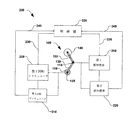
図5は、ブロックダイアグラム形式による本発明の他の実施形態を示すものであり、スキャニングシステム200は、図1のスキャニング機構100を含んでいる。図5において、例えば、第1回転アクチュエータ205は、第1ジョイント125と関係し、第2回転アクチュエータ210は、第2ジョイント130と関係し、そして、上記第1アクチュエータ及び第2アクチュエータは、第1及び第2リンク115、120それぞれに、回転力を供給するように作動可能である。例えば、第1及び第2回転アクチュエータ205、210は、図1の第1回転方向128及び第2回転方向それぞれにおいて、それぞれの第1リンク115及び第2リンク120を回転作動させる1以上のサーボモータあるいは回転装置を含んでいる。
FIG. 5 shows another embodiment of the present invention in block diagram form, and the
図5のスキャニングシステム200は、例えば、第1及び第2アクチュエータ205、210それぞれと関連する第1感知要素215及び第2感知要素220をさらに含んでおり、上記第1及び第2の感知要素は、さらに、位置あるいは第1及び第2リンクそれぞれの速度あるいは加速度のような他の運動学的パラメータを、感知するように作動可能である。さらに、本発明の他の実施形態によれば、制御器225(例 多軸運動制御器)は、第1及び第2アクチュエータ205、210と第1及び第2感知要素215、220の図示されないドライバー及び/あるいは増幅器に作動可能に接続される。そして制御器225は、関連する制御デューティサイクル(例 図4に示す最大位置155と160の間の、エンドエフェクタ140の移動)に対して上記第1及び第2回転アクチュエータそれぞれに供給される出力230、235(例 駆動信号)の量を制御するように作動可能である。エンコーダあるいはレゾルバのような、図5の第1及び第2感知要素215、200は、さらに、制御器225へそれぞれフィードバック信号240、245を供給するように作動可能であり、そして、上記アクチュエータ205、210それぞれへの駆動信号230及び235は、例えば、リアルタイムで計算される。そのような駆動信号230及び235のリアルタイムの計算により、所定の時間間隔で上記回転アクチュエータ205、210それぞれへの出力の正確な調整を可能にする。
The
本発明の運動(移動)制御の一般的考え方は、エンドエフェクタの円滑な移動を行わせるものであり、それと関連して速度エラーを最小にすることができる。他の実施形態によれば、制御器225は、さらに図示されない逆運動学的モデルを含み、エンドエフェクタ140の関節運動は、各ジョイント125、130それぞれのデューティサイクルから得られる。例えば、制御器225は、さらに、各制御デューテイサイクル中、前進送り量、各ジョイント125、130に対してモデルに基づくコンプリメンタリートルクを計算することによって、各アクチュエータ205、210を制御するように作動可能である。
The general idea of motion (movement) control of the present invention is to allow the end effector to move smoothly, and in this connection, speed errors can be minimized. According to another embodiment, the
上記実施形態で説明したように、第1及び第2回転アクチュエータ205、210それぞれへ供給される上記出力230、235の量は、少なくとも部分的には、第1及び第2感知要素215、220それぞれによって感知された位置に基づくものである。したがって、スキャニング機構100のエンドエフェクタ140の位置は、第1及び第2アクチュエータ205、210に供給される出力量によって制御でき、その出力量は、さらに図1の第1スキャンパスに沿うエンドエフェクタの速度と加速度に関連している。例えば、図5の制御器225は、図4の移動機構170を制御するように作動可能であり、第2スキャンパス175に沿う基部105の移動は、さらに制御可能である。一実施形態によれば、移動機構170の各単位の移動(例 「スロースキャン」移動)は、第1スキャンパス142に沿うエンドエフェクタの移動(例 「急速スキャン」移動)と同期しており、その結果、上記移動機構は、イオンビーム中を基板165の各通過後(例 急速スキャンパスに沿うウエハの方向転換中)、単位量で移動される。
As described in the above embodiment, the amount of the
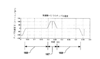
本発明の他の実施形態によれば、図3の第1および第2リンク115、120の回転速度プロファイルおよび加速度プロファイルは、予め定められており、速度及び加速度と関連する初期力は所定範囲168内で最小である。例えば、最大スキャン距離166は、イオンビームの利用と関連して回転サブシステム110の作業空間を定める。そして、第1及び第2リンク115、120は、往復移動の始点で最大長である(例 図2Aの第1位置150)。進歩した軌道及びパスの設計技術が、関節空間ばかりでなく操作空間で、移動プロファイルを設計するために使用されてよく、関節加速度と関連する大きな初期力は実質的に最小になる。また、これらの技術は、図5の関節アクチュエータ205、210と関連して、大きさや要求される出力を減少できる。例えば、図6A、6B及び6Cは、図3のエンドエフェクタ140の各時間での、加速度、速度、および位置を示す順運動学的グラフの例を説明するものである。この例で、時間は第1スキャンパスに沿うエンドエフェクタの位置と関連しており、一定速度が所定の範囲168内で望ましい。速度変換中(すなわち、エンドエフェクタ140の加速及び減速中)、基板はオーバーシュート167の領域にあることが望ましい。
According to another embodiment of the present invention, the rotational speed profile and acceleration profile of the first and
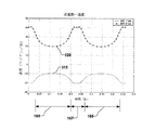
本発明の他の実施形態によれば、図3の第1及び第2リンク115、120が最大長155、160に近づくか、達した時、あるいはそれらが互いに折畳まれる時(例 図2Aと2Gは最大長を示し、図2Dと2Jは折畳まれた第1及び第2リンク115、120を示す)、適当な逆運動学的技術が特異性を克服するために使用することができる。例えば、モデル予測制御技術が第1スキャンパス142に沿って基板165を円滑に移動するために使用できる。図7A、7B、及び7Cに説明されるように、逆運動は、所定範囲168内の基板165を一定速度とするために、図3の第1ジョイント125および第2ジョイント130それぞれの、回転加速度プロファイル305、310、速度プロファイル315、320、及び位置プロファイル325、330を決めることができる。
According to other embodiments of the present invention, when the first and
本発明は、第1及び第2ジョイント125、130の回転速度を維持し、その結果、関節回転速度は、図7Bで示すように、第1及び第2リンク115、120の360度回転中、ゼロでクロス交わらない。速度ゼロで交差しない回転速度(したがって、回転方向)を維持することは、関節の加速度及び減速度と関連して大きな初期力を最小にする。それ故、大きな利点は、従来技術以上のものであり、第1及び第2アクチュエータは、同じ回転方向に連続的に回転する。図8は、逆運動を使用する図3の第1ジョイント125および第2ジョイント130それぞれに対するトルクプロファイル335、340の例を示す。さらに、従来のウエハスキャン機構と比較して、第1ジョイント125および第2ジョイント130と関連する上記トルクは、本発明によれば意義のある減少をしている、ということに注意されなければならない。
The present invention maintains the rotational speed of the first and
本発明のさらに他の実施形態によれば、図9は、図1のスキャニング機構の例の、調整(integration)と操作を説明する例示的方法400の概要ブロックダイアグラムである。例示的方法は、一連の行動あるいは事項として説明されかつ記載されているが、本発明によれば、いくつかの工程は異なった順序及び/あるいは他の工程と同時に起るので、本発明はこのような行動あるいは事項の説明される順序によって制限されない、ということが理解されるであろう。加えて、図示されない全ての工程が、本発明による方法を実行することを要求されてよい。さらに、上記方法は、図示されない他のシステムと関連するばかりでなく、ここに説明され、記載されているシステムと関連して実行されることが理解されるであろう。
According to yet another embodiment of the present invention, FIG. 9 is a schematic block diagram of an
図9に示されるように、行為405において2−リンク回転機構を備えることにより開始され、ジョイント間の距離は、略等しい。リンクの回転速度は行為410で制御され、エンドエフェクタは二つの最大位置間を往復し、エンドエフェクタの速度は所定範囲内で、通常、一定に維持される。例えば、所定範囲内でイオンビームは基板に衝突し、基板はその移動中、イオンビームに一様に曝される。所定の制御計画が使用され、その結果、関節アクチュエータのリンクによってもたらされる初期の、コリオリの力及び/あるいは求心力が補償される。
As shown in FIG. 9, the
本発明のスキャニング機構100(例 関節腕)は、十分な機敏さを提供し、その結果、スキャニング機構が材料を取り扱う業務に容易に使用できる。そのような材料取扱作業は、例えば、他の移動機構に処理したウエハを置き、あるいは輸送することを含む。逆に、未処理のウエハのローディングあるいはピッキングは、他の移動装置と協働することによって達成される。 The scanning mechanism 100 (e.g., articulated arm) of the present invention provides sufficient agility, so that the scanning mechanism can be easily used in business handling materials. Such material handling operations include, for example, placing or transporting processed wafers on other transfer mechanisms. Conversely, loading or picking of unprocessed wafers is accomplished by cooperating with other transfer devices.
本発明の他の実施形態によれば、スキャニング機構100は図示されない高真空状態にあって、潤滑されたベアリングやアクチュエータのような機械的要素が、環境に直接、曝されていない処理室で使用できる。そのような目的を達成するために、例えば、上記機構100のジョイントは、磁性流体(Ferro-fluidic)シールのような真空シールを備える。工程のクリーン度を完全にするための、いかなる可動真空シールも、本発明の範囲内に含まれることが理解されるべきである。それ故、本発明は、さらに、クリーンな真空の環境内で、移動し、ウエハスキャンを行うように作動可能である。
According to another embodiment of the present invention, the
本発明は、ある好ましい実施形態に関して記載されているが、等しい変更や変形が、この明細書や添付の図面を読み、理解すれば、他の技術分野で生じることは明らかである。特に、上述した要素(アッセンブリ、装置、回路等)によって達成される多くの機能をみれば、そのような要素を記述するのに使用された上記用語(手段を含む)は、たとえ本発明のここに説明された例示的な実施形態の機能を達成する開示の構造に、構造的に等しくないとしても、上述の要素(例 機能的に等しいもの)の特殊な機能を達成する要素のいずれかに、他に示されていなくとも、相当するものと解釈される。加えて、本発明の他の特徴は、いくつかの実施形態の一つのみについて開示されたものではなく、そのような特徴は、与えられたあるいは特殊な応用のために有効かつ望ましいものとして、他の実施形態の特徴と結合される。 Although the invention has been described with reference to certain preferred embodiments, it will be apparent that equivalent changes and modifications may occur in other technical fields upon reading and understanding this specification and the accompanying drawings. In particular, in view of the many functions achieved by the above-described elements (assemblies, devices, circuits, etc.), the terms used to describe such elements (including means) are not limited to the present invention. Any of the elements that achieve the special functions of the above-described elements (eg, functionally equivalent), even if not structurally equivalent to the disclosed structure that achieves the functions of the exemplary embodiments described in FIG. , It is interpreted as equivalent if not otherwise indicated. In addition, other features of the present invention are not disclosed for only one of several embodiments, and such features may be useful and desirable for a given or special application, Combined with the features of other embodiments.
100 スキャニング機構
105 基部
110 回転サブシステム
115 第1リンク
120 第2リンク
125 第1ジョイント125
127 第1軸
128 第1回転方向
130 第2ジョイント
133 第2回転方向
132 第2軸
134 第1回転パス
135 第2回転パス
140 エンドエフェクタ
142 第1スキャンパス
100
127
Claims (27)
前記回転サブシステムは、
基部に回転可能に連結されている第1ジョイントを含む第1リンクと、前記第1リンクと互いに所定距離離れており、前記第1リンクに回転可能に連結される第2ジョイントを含む第2リンクと、所定距離上記第2ジョイントから離れていて、基部があり、前記第2リンクに作動可能に連結され、前記第2リンクに含まれるエンドエフェクタと、
第1回転方向において、前記第1ジョイントの周囲で前記第1リンクを連続的に回転させるように作動可能な第1アクチュエータと、
第2回転方向において、前記第2ジョイントの周囲で前記第2リンクを連続的に回転させるように作動可能な第2アクチュエータと、を含み、
前記エンドエフェクタは前記第1及び第2アクチュエータの回転に際して、第1スキャンパスに沿って前期基部に関して線形往復運動するように作動可能であるスキャニング装置。 A scanning device for processing a substrate, comprising a base and a rotating subsystem,
The rotation subsystem includes:
A first link including a first joint rotatably connected to a base, and a second link including a second joint that is spaced apart from the first link by a predetermined distance and is rotatably connected to the first link. A predetermined distance away from the second joint, having a base, operatively connected to the second link, and an end effector included in the second link;
A first actuator operable in a first rotation direction to continuously rotate the first link around the first joint;
A second actuator operable to continuously rotate the second link about the second joint in a second rotational direction;
A scanning device, wherein the end effector is operable to reciprocate linearly with respect to the base portion along a first scan path during rotation of the first and second actuators.
請求項1記載のスキャニング装置。 The controller of claim 1, further comprising a controller operable to control a rotational speed of each of the first and second links by controlling an output amount provided in each of the first and second actuators. Scanning device.
回転サブシステムは基部に第1ジョイントによって回転可能に連結された第1リンクを含み、前記回転サブシステムは、さらに第2ジョイントによって第1リンクへ回転可能に連結される第2リンクを含み、そして、第1ジョイントと第2ジョイント間の距離は、通常、第2ジョイントと上記エンドエフェクタ間の距離に等しい、2−リンクの前記回転サブシステムと関連するエンドエフェクタ上に基板を備え、
第1回転方向及び第2回転方向それぞれにおいて、上記第1リンク及び第2リンクを回転し、
上記エンドエフェクタは通常、一直線上で線形移動するように、第1リンク及び第2リンクのそれぞれの回転速度を制御し、上記第1回転方向及び第2回転方向は一定であることを含む基板のスキャニング方法。 A scanning method,
The rotating subsystem includes a first link rotatably connected to a base by a first joint, the rotating subsystem further including a second link rotatably connected to the first link by a second joint; and The distance between the first joint and the second joint is usually equal to the distance between the second joint and the end effector, comprising a substrate on the end effector associated with the two-link rotating subsystem;
Rotating the first link and the second link in each of the first rotation direction and the second rotation direction;
The end effector usually controls the rotational speed of each of the first link and the second link so as to linearly move on a straight line, and the first rotation direction and the second rotation direction are constant. Scanning method.
Applications Claiming Priority (1)
| Application Number | Priority Date | Filing Date | Title |
|---|---|---|---|
| US10/786,660 US7112808B2 (en) | 2004-02-25 | 2004-02-25 | Wafer 2D scan mechanism |
Publications (2)
| Publication Number | Publication Date |
|---|---|
| JP2005244227A true JP2005244227A (en) | 2005-09-08 |
| JP2005244227A5 JP2005244227A5 (en) | 2008-03-13 |
Family
ID=34861806
Family Applications (1)
| Application Number | Title | Priority Date | Filing Date |
|---|---|---|---|
| JP2005045898A Withdrawn JP2005244227A (en) | 2004-02-25 | 2005-02-22 | Two-dimensional scanning mechanism of wafer |
Country Status (2)
| Country | Link |
|---|---|
| US (1) | US7112808B2 (en) |
| JP (1) | JP2005244227A (en) |
Families Citing this family (10)
| Publication number | Priority date | Publication date | Assignee | Title |
|---|---|---|---|---|
| US7112808B2 (en) | 2004-02-25 | 2006-09-26 | Axcelis Technologies, Inc. | Wafer 2D scan mechanism |
| US7323695B2 (en) * | 2004-04-05 | 2008-01-29 | Axcelis Technologies, Inc. | Reciprocating drive for scanning a workpiece |
| KR20060128001A (en) * | 2004-04-09 | 2006-12-13 | 액셀리스 테크놀로지스, 인크. | Wafer scanning system with reciprocating rotary motion utilizing springs and counterweights |
| US7119343B2 (en) * | 2004-05-06 | 2006-10-10 | Axcelis Technologies, Inc. | Mechanical oscillator for wafer scan with spot beam |
| CN1291445C (en) * | 2004-06-18 | 2006-12-20 | 清华大学 | Target disc angle controlling and scanning motion mechanism of ion implantation apparatus |
| KR20080078703A (en) * | 2005-12-01 | 2008-08-27 | 텔 에피온 인크 | Method and apparatus for scanning a workpiece through an ion beam |
| US20080023654A1 (en) * | 2006-07-28 | 2008-01-31 | Michael Graf | Method of reducing transient wafer temperature during implantation |
| US7582883B2 (en) * | 2007-01-12 | 2009-09-01 | Applied Materials, Inc. | Method of scanning a substrate in an ion implanter |
| US9029808B2 (en) | 2011-03-04 | 2015-05-12 | Tel Epion Inc. | Low contamination scanner for GCIB system |
| US8791430B2 (en) | 2011-03-04 | 2014-07-29 | Tel Epion Inc. | Scanner for GCIB system |
Family Cites Families (24)
| Publication number | Priority date | Publication date | Assignee | Title |
|---|---|---|---|---|
| US4736107A (en) | 1986-09-24 | 1988-04-05 | Eaton Corporation | Ion beam implanter scan control system |
| US5737500A (en) * | 1992-03-11 | 1998-04-07 | California Institute Of Technology | Mobile dexterous siren degree of freedom robot arm with real-time control system |
| US5486080A (en) | 1994-06-30 | 1996-01-23 | Diamond Semiconductor Group, Inc. | High speed movement of workpieces in vacuum processing |
| US6428266B1 (en) * | 1995-07-10 | 2002-08-06 | Brooks Automation, Inc. | Direct driven robot |
| US5741113A (en) * | 1995-07-10 | 1998-04-21 | Kensington Laboratories, Inc. | Continuously rotatable multiple link robot arm mechanism |
| US5746565A (en) | 1996-01-22 | 1998-05-05 | Integrated Solutions, Inc. | Robotic wafer handler |
| JP3729604B2 (en) | 1997-06-16 | 2005-12-21 | 住友イートンノバ株式会社 | Ion implanter |
| US6384418B1 (en) | 1998-05-18 | 2002-05-07 | Seiko Instruments Inc. | Sample transfer apparatus and sample stage |
| GB2382716B (en) | 1998-07-21 | 2003-09-03 | Applied Materials Inc | Ion Implantation Beam Monitor |
| US6207959B1 (en) | 1999-04-19 | 2001-03-27 | Applied Materials, Inc. | Ion implanter |
| EP1056114A3 (en) | 1999-05-24 | 2007-05-09 | Applied Materials, Inc. | Ion implantation apparatus |
| JP3976455B2 (en) | 1999-09-17 | 2007-09-19 | 株式会社日立製作所 | Ion implanter |
| US6515288B1 (en) | 2000-03-16 | 2003-02-04 | Applied Materials, Inc. | Vacuum bearing structure and a method of supporting a movable member |
| US6677599B2 (en) | 2000-03-27 | 2004-01-13 | Applied Materials, Inc. | System and method for uniformly implanting a wafer with an ion beam |
| EP1285456A2 (en) | 2000-05-15 | 2003-02-26 | Varian Semiconductor Equipment Associates Inc. | High efficiency scanning in ion implanters |
| US20020125446A1 (en) | 2001-02-20 | 2002-09-12 | Vanderpot John W. | Substrate positioning system |
| JP4061044B2 (en) | 2001-10-05 | 2008-03-12 | 住友重機械工業株式会社 | Substrate moving device |
| WO2003046958A2 (en) * | 2001-11-29 | 2003-06-05 | Diamond Semiconductor Group, Llc. | Wafer handling apparatus and method |
| US6956223B2 (en) | 2002-04-10 | 2005-10-18 | Applied Materials, Inc. | Multi-directional scanning of movable member and ion beam monitoring arrangement therefor |
| US6908836B2 (en) | 2002-09-23 | 2005-06-21 | Applied Materials, Inc. | Method of implanting a substrate and an ion implanter for performing the method |
| GB2389958B (en) | 2002-06-21 | 2005-09-07 | Applied Materials Inc | Multi directional mechanical scanning in an ion implanter |
| US7049210B2 (en) | 2002-09-23 | 2006-05-23 | Applied Materials, Inc. | Method of implanting a substrate and an ion implanter for performing the method |
| US7112808B2 (en) | 2004-02-25 | 2006-09-26 | Axcelis Technologies, Inc. | Wafer 2D scan mechanism |
| US6953942B1 (en) | 2004-09-20 | 2005-10-11 | Axcelis Technologies, Inc. | Ion beam utilization during scanned ion implantation |
-
2004
- 2004-02-25 US US10/786,660 patent/US7112808B2/en not_active Expired - Fee Related
-
2005
- 2005-02-22 JP JP2005045898A patent/JP2005244227A/en not_active Withdrawn
Also Published As
| Publication number | Publication date |
|---|---|
| US7112808B2 (en) | 2006-09-26 |
| US20050184253A1 (en) | 2005-08-25 |
Similar Documents
| Publication | Publication Date | Title |
|---|---|---|
| JP2005244227A (en) | Two-dimensional scanning mechanism of wafer | |
| US8078304B2 (en) | Dual-mode robot systems and methods for electronic device manufacturing | |
| JP5004052B2 (en) | Method for reciprocating a workpiece through an ion beam | |
| JP5304979B2 (en) | Improved ion beam used during ion implantation scans | |
| JP4784872B2 (en) | Reciprocating drive for scanning a workpiece | |
| JP4840607B2 (en) | Wafer scanning system with reciprocating rotational motion using spring and counterweight | |
| JP2008519417A (en) | Improved uniformity of dose during scanned ion implantation | |
| US7119343B2 (en) | Mechanical oscillator for wafer scan with spot beam | |
| TWI610348B (en) | Electrode adjustment assembly and method for adjusting electrode | |
| KR102717630B1 (en) | Alignment Stage, Tramsfer System and Method Using the Alignment Stage | |
| JP7315905B2 (en) | Substrate transfer device | |
| WO2006121431A1 (en) | Mechanical oscillator for wafer scan with spot beam | |
| JP2024519460A (en) | Rotary indexer with wafer centering function | |
| JP2008047525A (en) | Method of reducing wafer temperature temporarily during ion implantation |
Legal Events
| Date | Code | Title | Description |
|---|---|---|---|
| A521 | Request for written amendment filed |
Free format text: JAPANESE INTERMEDIATE CODE: A523 Effective date: 20080125 |
|
| A621 | Written request for application examination |
Free format text: JAPANESE INTERMEDIATE CODE: A621 Effective date: 20080125 |
|
| A761 | Written withdrawal of application |
Free format text: JAPANESE INTERMEDIATE CODE: A761 Effective date: 20091105 |


