JP2005243129A - Disk cartridge - Google Patents
Disk cartridge Download PDFInfo
- Publication number
- JP2005243129A JP2005243129A JP2004050488A JP2004050488A JP2005243129A JP 2005243129 A JP2005243129 A JP 2005243129A JP 2004050488 A JP2004050488 A JP 2004050488A JP 2004050488 A JP2004050488 A JP 2004050488A JP 2005243129 A JP2005243129 A JP 2005243129A
- Authority
- JP
- Japan
- Prior art keywords
- cartridge
- shutter
- insertion hole
- disk
- case
- Prior art date
- Legal status (The legal status is an assumption and is not a legal conclusion. Google has not performed a legal analysis and makes no representation as to the accuracy of the status listed.)
- Pending
Links
- 238000003780 insertion Methods 0.000 claims description 50
- 230000037431 insertion Effects 0.000 claims description 50
- 230000001105 regulatory effect Effects 0.000 claims description 3
- 230000001276 controlling effect Effects 0.000 claims 1
- 230000006866 deterioration Effects 0.000 abstract description 2
- 230000002265 prevention Effects 0.000 description 15
- 238000000034 method Methods 0.000 description 7
- 239000000463 material Substances 0.000 description 5
- 239000013078 crystal Substances 0.000 description 3
- 239000000428 dust Substances 0.000 description 2
- 230000003287 optical effect Effects 0.000 description 2
- 239000000758 substrate Substances 0.000 description 2
- 230000015572 biosynthetic process Effects 0.000 description 1
- GQYHUHYESMUTHG-UHFFFAOYSA-N lithium niobate Chemical compound [Li+].[O-][Nb](=O)=O GQYHUHYESMUTHG-UHFFFAOYSA-N 0.000 description 1
- 230000013011 mating Effects 0.000 description 1
- 239000011159 matrix material Substances 0.000 description 1
- 239000000203 mixture Substances 0.000 description 1
- 239000003973 paint Substances 0.000 description 1
- 230000002093 peripheral effect Effects 0.000 description 1
- 229920000642 polymer Polymers 0.000 description 1
- 239000002904 solvent Substances 0.000 description 1
Images


Classifications
-
- G—PHYSICS
- G11—INFORMATION STORAGE
- G11B—INFORMATION STORAGE BASED ON RELATIVE MOVEMENT BETWEEN RECORD CARRIER AND TRANSDUCER
- G11B23/00—Record carriers not specific to the method of recording or reproducing; Accessories, e.g. containers, specially adapted for co-operation with the recording or reproducing apparatus ; Intermediate mediums; Apparatus or processes specially adapted for their manufacture
- G11B23/02—Containers; Storing means both adapted to cooperate with the recording or reproducing means
- G11B23/03—Containers for flat record carriers
- G11B23/0301—Details
- G11B23/0308—Shutters
-
- G—PHYSICS
- G11—INFORMATION STORAGE
- G11B—INFORMATION STORAGE BASED ON RELATIVE MOVEMENT BETWEEN RECORD CARRIER AND TRANSDUCER
- G11B23/00—Record carriers not specific to the method of recording or reproducing; Accessories, e.g. containers, specially adapted for co-operation with the recording or reproducing apparatus ; Intermediate mediums; Apparatus or processes specially adapted for their manufacture
- G11B23/02—Containers; Storing means both adapted to cooperate with the recording or reproducing means
- G11B23/03—Containers for flat record carriers
- G11B23/0301—Details
- G11B23/0313—Container cases
- G11B23/0316—Constructional details, e.g. shape
Abstract
Description
本発明は、光ディスクなどの情報記録媒体を回転可能に収納して記録再生を行うためのディスクカートリッジの構造に係り、特に、ホログラム媒体に好適な遮光性と防塵性を兼ね備えたディスクカートリッジの構造に関する。 The present invention relates to a structure of a disk cartridge for storing and reproducing an information recording medium such as an optical disk in a rotatable manner, and more particularly, to a structure of a disk cartridge having both light shielding and dust resistance suitable for a hologram medium. .
デジタルホログラム記録は、従来の光ディスクとは異なり、記録光と参照光の干渉を利用して、記録層の厚み方向の干渉点に記録し、参照光で干渉点に記録された情報を読み出す方式であり、一回の光照射で大量のデータが記録できる点と相俟って、大容量かつ高速の情報記録/再生が可能である。 Unlike conventional optical discs, digital hologram recording is a method of recording at the interference point in the thickness direction of the recording layer using the interference between the recording light and the reference light, and reading the information recorded at the interference point with the reference light. In combination with the fact that a large amount of data can be recorded with a single light irradiation, large-capacity and high-speed information recording / reproduction is possible.
従来のホログラム記録に用いる記録媒体は、ニオブ酸リチウム単結晶のようなフォトリフラクティブ結晶と呼ばれる無機単結晶が主体であり、高価格かつ加工困難という問題点を有していた。これに対し、光重合性材料をベースとした有機系ホログラム材料は、上記問題点に対し劇的な改善が期待でき、近年研究が進められている。この有機系のホログラム記録用材料には、記録材料である光重合性材料をその支持媒体となる高分子マトリックスに混合・分散したものが用いられ、記録媒体作成にあたっては、これを溶剤に希釈して塗料とし基板上に塗布するか、あるいはこれをフィルム状に加工して基材に貼付する方法が取られている。 A recording medium used for conventional hologram recording is mainly composed of an inorganic single crystal called a photorefractive crystal such as a lithium niobate single crystal, and has a problem that it is expensive and difficult to process. On the other hand, organic hologram materials based on photopolymerizable materials can be expected to drastically improve the above-mentioned problems, and research has been conducted in recent years. This organic hologram recording material is a mixture of a photopolymerizable material, which is a recording material, mixed and dispersed in a polymer matrix as a supporting medium. When preparing a recording medium, this is diluted with a solvent. In this method, a paint is applied on a substrate or processed into a film and pasted on a substrate.
ところで、ホログラム記録においてはレーザーなどの記録光により記録を行うため、記録を行うまでにいかに遮光して未記録の状態で保存しておくかが重要である。例えば特許文献1では、遮光性カートリッジにホログラム媒体を収納し、記録再生装置に装着する際に駆動軸挿入孔とヘッドアクセス孔をシャッターにより開閉して保存時の遮光性を確保する手法が提案されている。また、防塵性を高める手法として、例えば特許文献2のようにカートリッジ構造を二重にすることが提案されている。また、ISOの5.25型MOカートリッジと同型状のカートリッジでホログラム媒体を提供する提案がなされている。
By the way, in hologram recording, since recording is performed using recording light such as a laser, it is important how light is shielded and stored in an unrecorded state before recording. For example, Patent Document 1 proposes a method for securing a light-shielding property during storage by storing a hologram medium in a light-shielding cartridge and opening and closing a drive shaft insertion hole and a head access hole with a shutter when the recording medium is mounted on a recording / reproducing apparatus. ing. Further, as a technique for improving the dustproof property, for example, it has been proposed to double the cartridge structure as in
しかしながら特許文献1記載の技術では、シャッターとカートリッジの間にはシャッターをスライドされるための隙間を設ける必要があり、隙間から収納媒体に直接光が入射する可能性がある。そのため、遮光性、防塵性ともに十分ではない。 However, in the technique described in Patent Document 1, it is necessary to provide a gap for sliding the shutter between the shutter and the cartridge, and light may directly enter the storage medium from the gap. Therefore, neither light-shielding property nor dust-proof property is sufficient.
また、特許文献2に記載の構造のように二重構造のカートリッジを用い、シャッターを内側のカートリッジと外側のカートリッジの間に介在させる方法によれば、確かにヘッドアクセス孔および駆動軸挿入孔の部分についての遮光性、防塵性ともに問題は解消されるが、その他の部分についてはホログラム媒体を想定していないため、遮光性が問題となり、ホログラム媒体用のカートリッジとしては遮光性が不十分である。さらには、二重構造とするため、カートリッジ自体が収納するディスクの大きさに比べて全体的に大きくなる。
Further, according to the method of using a double-structure cartridge as in the structure described in
本発明は二重構造のカートリッジであっても小型化が可能であり、且つ、遮光性と防塵性を兼ね備えた、特にホログラム媒体等の光による劣化の起き易い情報記録媒体に好適なディスクカートリッジを提供することに有る。 The present invention provides a disc cartridge that can be downsized even with a double-structured cartridge and that is suitable for an information recording medium that has both light-shielding properties and dust-proof properties and that is particularly susceptible to deterioration due to light, such as a hologram medium. There is in providing.
本発明の第1の特徴は、インナーカートリッジとアウターカートリッジの間にシャッターがスライド可能に取り付けられているディスクカートリッジであって、アウターケースにおける上下ケースの接合面と、インナーケースにおける上下ケースの接合面の高さをずらした二重構造のカートリッジケースを提供することに有る。アウターケースにおける上下ケースの接合面と、インナーケースにおける上下ケースの接合面の高さをずらすことにより、ケースの断面が階段状になるため、光や塵埃が直線的に入りにくい構造となるため、結果として遮光性と防塵性を兼ね備えた構造を提供することができる。 A first feature of the present invention is a disc cartridge in which a shutter is slidably mounted between an inner cartridge and an outer cartridge, and the joining surface of the upper and lower cases in the outer case and the joining surface of the upper and lower cases in the inner case It is to provide a cartridge case having a double structure in which the height of the cartridge is shifted. By shifting the height of the joint surface of the upper and lower cases in the outer case and the height of the joint surface of the upper and lower cases in the inner case, the cross section of the case becomes a staircase, so light and dust are difficult to enter linearly, As a result, it is possible to provide a structure having both light shielding properties and dustproof properties.
本発明の第2の特徴は、シャッターをスライド可能に取り付けるためのスライダーにシャッター位置決め用のピンを設け、シャッターにもこのスライダーのピンを挿入するための孔を設け、スライダーとシャッターを嵌め合わせ、さらにインナーケースとアウターケースの間にシャッターを介在させた二重構造のカートリッジを提供することに有る。シャッターのエッジ部分がインナーカートリッジとアウターカートリッジの間に入ることで遮光性と防塵性を兼ね備えた構造を提供することができる。また、ピンでシャッターの位置決めをし、さらにアウターケースとインナーケースによってシャッターのスライドを規制することにより、ねじなどによるシャッターの固定が不要となり、部品点数を減らすことによりカートリッジを簡易に組み立てることが可能になる。 A second feature of the present invention is that a slider for slidably mounting the shutter is provided with a shutter positioning pin, a hole for inserting the slider pin is also provided in the shutter, and the slider and the shutter are fitted, It is another object of the present invention to provide a double-structure cartridge in which a shutter is interposed between an inner case and an outer case. Since the shutter edge portion is inserted between the inner cartridge and the outer cartridge, it is possible to provide a structure having both light shielding properties and dustproof properties. In addition, by positioning the shutter with pins and regulating the shutter slide with the outer case and inner case, it is not necessary to fix the shutter with screws, etc., and it is possible to easily assemble the cartridge by reducing the number of parts become.
本発明の第3の特徴は、シャッターの上下側板の連結部がインナーケースとアウターケースの間を介在させ、ケースの外側に露出しない二重構造のカートリッジを提供することに有る。シャッター側板の連結部が外側に露出していないため不用意にシャッターが外れたり、変形したりし、また、シャッターを故意に開閉することを防止できるため、誤って未記録のホログラム媒体に光を当てる懸念がなくなる。 A third feature of the present invention is to provide a double-structure cartridge in which the connecting portion of the upper and lower side plates of the shutter is interposed between the inner case and the outer case, and is not exposed to the outside of the case. Since the connecting part of the shutter side plate is not exposed to the outside, the shutter can be inadvertently disconnected or deformed, and the shutter can be prevented from being opened and closed intentionally. No worries about hitting.
本発明の第4の特徴は、シャッターロック部材の回動部の中心をインナーケース側に設け、アウターケース側にシャッターロックの規制部を設けた二重構造のカートリッジが提供される。シャッターロック部材の回動部の中心をインナーケース側に設け、ロック部材の規制部をアウターケース側に設けることで、シャッターがスライドする際にインナーケースとアウターケースの嵌め合い段差によるスライドへの干渉を考慮する必要がなくなるため、スライダーの形状用途に合わせて自由に設計することが可能になる。 According to a fourth aspect of the present invention, there is provided a double-structure cartridge in which the center of the rotating portion of the shutter lock member is provided on the inner case side and the shutter lock restricting portion is provided on the outer case side. By providing the center of the rotating part of the shutter lock member on the inner case side and the restricting part of the lock member on the outer case side, when the shutter slides, it interferes with the slide due to the mating step between the inner case and the outer case. Therefore, it is possible to design freely according to the shape application of the slider.
本発明の第5の特徴は、アウターケースに設けたインナーケース位置決め用のピンと、位置決め用のピン挿入孔を設けたインナーケースによる二重構造のカートリッジが提供される。アウターケースとインナーケースに夫々位置決め用のピンと孔を設けることにより、インナーケースとアウターケースの位置決めを容易にするだけでなく、インナーケースの上下ケースを固定するため部材をこのピンと孔で代用することができ、部品点数を減らして組み立てを容易にすることが可能になる。 According to a fifth aspect of the present invention, there is provided a double-structure cartridge comprising an inner case positioning pin provided in an outer case and an inner case provided with a positioning pin insertion hole. In addition to facilitating positioning of the inner case and outer case by providing positioning pins and holes in the outer case and inner case, respectively, substitute the pins and holes for fixing the upper and lower cases of the inner case. It is possible to reduce the number of parts and facilitate assembly.
本発明の第6の特徴は、インナーケースとアウターケースのディスク収納部における最大横幅に対応する部分を、薄肉部で構成するディスクカートリッジが提供される。インナーケースの最大横幅部分を収納するディスク外形とほぼ同一にするため薄肉部を設け、その部分に対応するアウターケースも薄肉部で構成することにより、二重構造にしても外形を大きくすることがなく、例えばISO規格の5.25型光磁気ディスクと同型サイズの二重構造カートリッジを提供することができる。 According to a sixth aspect of the present invention, there is provided a disc cartridge in which a portion corresponding to the maximum lateral width in the disc storage portion of the inner case and the outer case is constituted by a thin portion. By providing a thin part to make the outer shape of the disk that accommodates the maximum width of the inner case almost the same as the outer case, and forming the outer case corresponding to that part with a thin part, the outer shape can be enlarged even in a double structure. For example, a double-structure cartridge having the same size as the ISO standard 5.25 type magneto-optical disk can be provided.
本発明の第7の特徴は、カートリッジ幅方向の中心付近にシャッターが設けられており、左右どちらか一方向にしかシャッター開閉動作が出来ない構造のカートリッジにおいて、ドライブにシャッター開閉アーム2組と誤挿入防止アームを設け、カートリッジにはアーム逃がしの凹形状と、凹形状の逆方向挿入防止ストッパーを組み合わせて設けることによって、片面記録ディスクが収納された片面仕様カートリッジと、両面記録ディスクが収納された両面仕様カートリッジが混在しても、片面仕様カートリッジは正方向のみの挿入ができ、両面仕様カートリッジは正逆両方の挿入ができることを可能とするシャッター開閉構造を有するカートリッジと、それを記録再生するための装置を提供することに有る。 The seventh feature of the present invention is that, in a cartridge having a structure in which a shutter is provided in the vicinity of the center in the cartridge width direction and the shutter can be opened and closed only in one of the left and right directions, the drive is mistaken for two sets of shutter opening and closing arms. An insertion prevention arm is provided, and the cartridge is provided with a combination of a concave shape for arm relief and a concave reverse insertion prevention stopper, so that a single-sided cartridge containing a single-sided recording disc and a double-sided recording disc are accommodated. Even if a double-sided cartridge is mixed, a single-sided cartridge can be inserted only in the forward direction, and a double-sided cartridge can be inserted in both the forward and reverse directions, and for recording and reproducing the cartridge. It is to provide a device.
本発明における二重構造のディスクカートリッジを用いることで、遮光性と防塵性に優れ、さらに、二重構造であっても部品点数が少なく、通常のカートリッジと同型サイズの二重構造カートリッジを提供することが可能になり、ホログラム媒体などの高い遮光性が必要となる情報記録媒体用のカートリッジとして好適である。 By using the double-structure disc cartridge according to the present invention, there is provided a double-structure cartridge that is excellent in light-shielding properties and dust-proof properties, and has the same number of parts as a normal cartridge with a small number of parts even in the double-structure. Therefore, it is suitable as a cartridge for an information recording medium that requires high light-shielding properties such as a hologram medium.
以下、本発明に従う実施例について説明するが、本発明はこれに限定されるものではない。 Hereinafter, examples according to the present invention will be described, but the present invention is not limited thereto.
以下、本発明の実施例を図面を用いて説明する。 Embodiments of the present invention will be described below with reference to the drawings.
(二重構造カートリッジの構成)
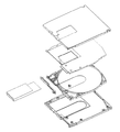
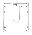
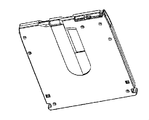
図1は実施例に係るディスクカートリッジの分解斜視図、図2はそのディスクカートリッジの正面図、図3はそのディスクカートリッジの裏面図である。
(Configuration of double structure cartridge)
1 is an exploded perspective view of a disk cartridge according to an embodiment, FIG. 2 is a front view of the disk cartridge, and FIG. 3 is a back view of the disk cartridge.
本発明の実施例に係るディスクカートリッジは、カートリッジケース1と、スライダー2と、ロック部材3と、シャッター4とから主に構成されている。
The disk cartridge according to the embodiment of the present invention mainly includes a cartridge case 1, a
前記カートリッジケース1は、インナー上ハーフ5aとインナー下ハーフ5bとからなるインナーケース5と、そのインナーケース5の厚さ方向の外側に配置されたアウター上ハーフ6aとアウター下ハーフ6bとからなるアウターケース6の2重ケース構造になっている。 The cartridge case 1 includes an inner case 5 composed of an inner upper half 5a and an inner lower half 5b, and an outer upper half 6a and an outer lower half 6b disposed outside the inner case 5 in the thickness direction. The case 6 has a double case structure.
前記アウター上ハーフ6aには図1ならびに図2に示されているように、前方のほぼ中央にアウター上ヘッド挿入孔7aが形成され、前記アウター下ハーフ6bには図1ならびに図3に示されているように、前方のほぼ中央にアウター下ヘッドおよびスピンドル挿入孔7bが、それぞれ形成されている。 As shown in FIGS. 1 and 2, the outer upper half 6a is formed with an outer upper head insertion hole 7a substantially at the front center, and the outer lower half 6b is shown in FIGS. As shown in the figure, an outer lower head and a spindle insertion hole 7b are respectively formed in the front center.
また図1に示すようにアウター下ハーフ6bの内面には、前記アウター下ヘッドおよびスピンドル挿入孔7bを内側に含んだ広さで一段と低くなった下凹部10bが設けられ、同様にアウター上ハーフ6aの内面にも図示しない下凹部10aが設けられている。この下凹部10a、10bの外形とほぼ対応するように図1に示す如くインナー上ハーフ5a、5bにも上凹部11a、11bが設けられている。この下凹部10a、10bと上凹部11a、11bによってインナー上ハーフ5aとアウター上ハーフ6aの間、およびインナー下ハーフ5bとアウター下ハーフ6bの間にシャッター4の上下平板部4a、4bが摺動する隙間が形成されるとともに、シャッター4の摺動範囲が規制されている。 Further, as shown in FIG. 1, the inner surface of the outer lower half 6b is provided with a lower concave portion 10b that includes the outer lower head and the spindle insertion hole 7b on the inner side and is further lowered. A lower recess 10a (not shown) is also provided on the inner surface of the. As shown in FIG. 1, upper concave portions 11a and 11b are also provided in the inner upper halves 5a and 5b so as to substantially correspond to the outer shapes of the lower concave portions 10a and 10b. The lower concave portions 10a and 10b and the upper concave portions 11a and 11b allow the upper and lower flat plate portions 4a and 4b of the shutter 4 to slide between the inner upper half 5a and the outer upper half 6a and between the inner lower half 5b and the outer lower half 6b. And a sliding range of the shutter 4 is restricted.
アウター上ハーフ6aおよびアウター下ハーフ6bは夫々同じ厚みで構成するが、インナー上ハーフ5aおよびインナー下ハーフ5bは厚みの比率を異ならせる。このように構成することにより、図10に示すようにインナーカートリッジとアウターカートリッジに段差を設けることで、遮光性と防塵性を高める構造にすることができる。 The outer upper half 6a and the outer lower half 6b are configured to have the same thickness, but the inner upper half 5a and the inner lower half 5b have different thickness ratios. By configuring in this way, as shown in FIG. 10, by providing a step in the inner cartridge and the outer cartridge, it is possible to achieve a structure that enhances the light shielding property and the dustproof property.
アウターカートリッジ6と、前記アウターカートリッジ6の内側に収納されるインナーカートリッジ5と、前記インナーカートリッジ5内に記録可能なディスクを回転可能に収納するカートリッジケースにおいて、前記インナーカートリッジ5の一部に前記ディスクの外周形状に沿った曲面部18を設ける、また、前記アウターカートリッジ6の前記曲面部18に対応する部分を肉薄部19としたことにより、同じ幅寸法のインナーカートリッジよりも大きな径のディスクを収納させることができる。 An outer cartridge 6, an inner cartridge 5 accommodated inside the outer cartridge 6, and a cartridge case for rotatably accommodating a recordable disc in the inner cartridge 5, wherein the disc is part of the inner cartridge 5. A curved portion 18 is provided along the outer peripheral shape of the outer cartridge 6 and a portion corresponding to the curved portion 18 of the outer cartridge 6 is a thin portion 19 so that a disk having a larger diameter than the inner cartridge having the same width can be accommodated. Can be made.
(スライダーとシャッターの取り付け)
シャッター4は、上下平板部4a、4bと連結部4cから構成される。シャッター4はスライダー2に組み合わされ、インナー上ハーフ5aに各々設けられたスライダー用レールA17aとインナー下ハーフ5bに設けられたスライダー用レールB17bに沿って摺動する。
(Attaching the slider and shutter)
The shutter 4 includes upper and lower flat plate portions 4a and 4b and a connecting portion 4c. The shutter 4 is combined with the
シャッター4はスライダー2に設けられたスライダー位置決め突起2aと、シャッター4の連結部4cに設けられた突起2aを嵌めるための孔4dによって図2に示す正面方向に対して左右方向に位置規制される。またアウターカートリッジ6によって図2に示す正面方向に対して上方向の位置が規制される。
The shutter 4 is regulated in the left-right direction with respect to the front direction shown in FIG. 2 by a slider positioning projection 2a provided on the
シャッター4の連結部4cは、アウター上ハーフ6aとアウター下ハーフ6bに設けられたアウター上ヘッド挿入孔7aとアウター下ヘッドおよびスピンドル挿入孔7bの端部を形成するブリッジ8a、8bにより覆われており、露出部がほとんどない。また、シャッターが開状態のときは、インナーカートリッジ5とアウターカートリッジ6の間にスライドして、シャッター全体が表面に露出しない構造となる。このような構造をとることにより、不用意にシャッターが開くのを防止することができる。 The connecting portion 4c of the shutter 4 is covered by an outer upper head insertion hole 7a provided in the outer upper half 6a and the outer lower half 6b, and bridges 8a and 8b that form ends of the outer lower head and the spindle insertion hole 7b. There are almost no exposed parts. Further, when the shutter is in the open state, it slides between the inner cartridge 5 and the outer cartridge 6 so that the entire shutter is not exposed on the surface. By taking such a structure, it is possible to prevent the shutter from being inadvertently opened.
(ロック機構)
シャッター4と前記シャッター4を摺動可能とするために前記シャッター4が組み付けられたスライダー2が全閉の位置でロックされるように前記スライダー2と契合するロック部材3と、インナーカートリッジ5とアウターカートリッジ6からなる二重カートリッジにおいて、ロック部材3の回動部中心3aをインナーカートリッジ5内に設け、アウターカートリッジ6にロック部材3の規制部6cを設けることで、スライダー2がシャッター4開閉のために摺動する面にインナーカートリッジ5とアウターカートリッジ6の不用意な嵌め合い段差が発生しない。ロックが解除されシャッター4がスライドする際に、スライダー2がインナーカートリッジ5とアウターカートリッジ6の嵌め合い段差によるスライドへの干渉を考慮する必要がなくなるため、スライダーの形状用途に合わせて自由に設計することが可能になる。
(Lock mechanism)
In order to make the shutter 4 and the shutter 4 slidable, the lock member 3 engaged with the
(誤挿入防止機構)
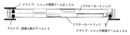
本発明の実施例に係るディスクカートリッジを記録再生する図示しないドライブにはシャッター開閉アーム13と誤挿入防止アーム14が設けられている。シャッター4を開閉させるためにカートリッジケース1に組み込まれているスライダー2に当接する位置にシャッター開閉アーム13が設けられており、またシャッター4全開時に、シャッター開動作を行わなかったもう一方のシャッター開閉アーム13と誤挿入防止アーム14が入り込むアーム逃がし凹形状15が設けられている。さらに、片面仕様のカートリッジケース1には逆方向挿入時に誤挿入防止アーム14が引っ掛る凹形状の逆方向挿入防止ストッパー16が設けられている。
(Incorrect insertion prevention mechanism)
A drive (not shown) for recording and reproducing a disk cartridge according to an embodiment of the present invention is provided with a shutter opening / closing arm 13 and an erroneous insertion preventing arm 14. A shutter opening / closing arm 13 is provided at a position in contact with the
ここでは便宜上、カートリッジケース1を正方向の挿入方向に対して右下側に設けられたシャッター開閉アーム13を開閉アームA13a、左上側に設けられたシャッター開閉アーム13を開閉アームB13bと称する。 Here, for convenience, the shutter opening / closing arm 13 provided on the lower right side of the cartridge case 1 with respect to the positive insertion direction is referred to as an opening / closing arm A13a, and the shutter opening / closing arm 13 provided on the upper left side is referred to as an opening / closing arm B13b.
図7に片面仕様のカートリッジケースのシャッター閉状態を示す。片面仕様のカートリッジケースが挿入されたとき、図8に示すように、正方向の挿入では開閉アームA13aはシャッター4を開動作し、開閉アームB13bおよび逆挿入防止アーム14はカートリッジケース1のドライブ挿入方向の面を滑り、シャッター4全開時付近でアーム逃がし凹形状15に入り込みシャッター4が全開する。逆方向への挿入時は、図9に示すように、誤挿入防止アーム14が誤挿入防止ストッパー16に引っ掛りそれ以上挿入できない。 FIG. 7 shows the shutter closed state of the single-sided cartridge case. When a single-sided cartridge case is inserted, as shown in FIG. 8, the opening / closing arm A13a opens the shutter 4 when inserted in the forward direction, and the opening / closing arm B13b and the reverse insertion preventing arm 14 are inserted into the cartridge case 1. The direction surface slips, the arm escapes into the concave shape 15 near the time when the shutter 4 is fully opened, and the shutter 4 is fully opened. At the time of insertion in the reverse direction, as shown in FIG. 9, the erroneous insertion prevention arm 14 is caught by the erroneous insertion prevention stopper 16 and cannot be further inserted.
両面仕様のカートリッジケース1が挿入されたときは、正方向の挿入時では片面仕様のカートリッジケース挿入と同様に開閉アームA13aはシャッター4を開動作し、開閉アームB13bおよび誤挿入防止アーム14はカートリッジケース1のドライブ挿入方向の面を滑り、シャッター4全開時付近でアーム逃がし凹形状15に入り込みシャッター4が全開する。逆方向の挿入は、開閉アームB13bがシャッター4を開動作し、開閉アームA13aおよび誤挿入防止アーム14はカートリッジケース1のドライブ挿入方向の面を滑り、シャッター4全開時付近でアーム逃がし凹形状15に入り込みシャッター4が全開する。 When the double-sided cartridge case 1 is inserted, the open / close arm A13a opens the shutter 4 and the open / close arm B13b and the erroneous insertion prevention arm 14 are in the cartridge when inserted in the forward direction, as in the case of single-sided cartridge case insertion. The surface of the case 1 in the drive insertion direction slides, the arm escapes into the concave shape 15 near the time when the shutter 4 is fully opened, and the shutter 4 is fully opened. For the insertion in the reverse direction, the opening / closing arm B13b opens the shutter 4, the opening / closing arm A13a and the erroneous insertion prevention arm 14 slide on the surface of the cartridge case 1 in the drive insertion direction, The entrance shutter 4 is fully opened.
1 カートリッジケース
2 スライダー
2a スライダー位置決め突起
3 ロック部材
3a ロック部材回動中心
4 シャッター
4a シャッター上板
4b シャッター下板
4c シャッター連結板
5 インナーカートリッジ
5a インナー上ハーフ
5b インナー下ハーフ
6 アウターカートリッジ
6a アウター上ハーフ
6b アウター下ハーフ
6c アウターカートリッジロック部材規制部
7a アウター上ヘッド挿入孔
7b アウター下ヘッド、スピンドル挿入孔
8a、8b ブリッジ
10a、10b 下凹部
11a、11b 上凹部
12 バネ
13 シャッター開閉アーム
13a 開閉アームA
13b 開閉アームB
14 誤挿入防止アーム
15 アーム逃がし凹形状
16 逆方向挿入防止ストッパー
17a スライダー用レールA
17b スライダー用レールB
18 インナーカートリッジ曲面部
19 アウターカートリッジ肉薄部
DESCRIPTION OF SYMBOLS 1
13b Open / close arm B
14 Accidental insertion prevention arm 15 Arm escape recess 16 Reverse insertion prevention stopper 17a Slider rail A
17b Slider rail B
18 Inner cartridge curved surface part 19 Outer cartridge thin part
Claims (6)
前記アウターカートリッジおよび前記インナーカートリッジは上下ハーフにより構成され、前記アウターカートリッジにおける上下ハーフの接合面と、前記インナーカートリッジにおける上下ハーフの接合面とを異なる面に配置したことを特徴とするディスクカートリッジ。 An outer cartridge, an inner cartridge housed inside the outer cartridge, and a disk cartridge that rotatably stores a recordable disk in the inner cartridge,
The outer cartridge and the inner cartridge are constituted by upper and lower halves, and the upper and lower half joining surfaces of the outer cartridge and the upper and lower half joining surfaces of the inner cartridge are arranged on different surfaces.
前記シャッターは上下面板と前記上下面板を連結する連結板を備え、前記スライダーには突起部が設けられ、前記連結板には前記突起部と嵌合するための孔部を設け、前記上下面板は前記インナーカートリッジとアウターカートリッジの間に配置し、シャッターを摺動可能に取り付けたことを特徴とするディスクカートリッジ。 An outer cartridge provided with a head insertion hole and a spindle insertion hole, an inner cartridge housed inside the outer cartridge and provided with a head insertion hole and a spindle insertion hole, and the head insertion hole and the spindle insertion hole are opened and closed. A disc cartridge that includes a shutter for sliding and a slider for sliding the shutter, and rotatably stores a recordable disc in the inner cartridge,
The shutter includes an upper and lower surface plate and a connection plate that connects the upper and lower surface plates, the slider has a protrusion, the connection plate has a hole for fitting with the protrusion, and the upper and lower surface plate A disc cartridge, which is disposed between the inner cartridge and the outer cartridge and has a shutter slidably attached thereto.
前記アウターカートリッジの内側に凸部を設け、前記インナーカートリッジの前記凸部と対応する部分に凹部を設けたことを特徴とするディスクカートリッジ。 An outer cartridge, an inner cartridge housed inside the outer cartridge, and a disk cartridge that rotatably stores a recordable disk in the inner cartridge,
A disc cartridge, wherein a convex portion is provided inside the outer cartridge, and a concave portion is provided in a portion corresponding to the convex portion of the inner cartridge.
6. The disk cartridge according to claim 1, wherein the recordable disk is a hologram medium.
Priority Applications (2)
| Application Number | Priority Date | Filing Date | Title |
|---|---|---|---|
| JP2004050488A JP2005243129A (en) | 2004-02-25 | 2004-02-25 | Disk cartridge |
| US11/062,876 US7373649B2 (en) | 2004-02-25 | 2005-02-23 | Disk cartridge |
Applications Claiming Priority (1)
| Application Number | Priority Date | Filing Date | Title |
|---|---|---|---|
| JP2004050488A JP2005243129A (en) | 2004-02-25 | 2004-02-25 | Disk cartridge |
Publications (2)
| Publication Number | Publication Date |
|---|---|
| JP2005243129A true JP2005243129A (en) | 2005-09-08 |
| JP2005243129A5 JP2005243129A5 (en) | 2007-04-12 |
Family
ID=34917889
Family Applications (1)
| Application Number | Title | Priority Date | Filing Date |
|---|---|---|---|
| JP2004050488A Pending JP2005243129A (en) | 2004-02-25 | 2004-02-25 | Disk cartridge |
Country Status (2)
| Country | Link |
|---|---|
| US (1) | US7373649B2 (en) |
| JP (1) | JP2005243129A (en) |
Cited By (5)
| Publication number | Priority date | Publication date | Assignee | Title |
|---|---|---|---|---|
| JP2007087519A (en) * | 2005-09-22 | 2007-04-05 | Fujifilm Corp | Recording and reproducing apparatus for photosensitive recording medium and cartridge for the same |
| JP2007087521A (en) * | 2005-09-22 | 2007-04-05 | Fujifilm Corp | Photosensitive recording medium, and recording and reproducing apparatus thereof |
| JP2007087522A (en) * | 2005-09-22 | 2007-04-05 | Fujifilm Corp | Photosensitive recording medium, and recording and reproducing apparatus therefor |
| JP2007200430A (en) * | 2006-01-25 | 2007-08-09 | Fujifilm Corp | Cartridge for photosensitive recording medium |
| JP2007234080A (en) * | 2006-02-27 | 2007-09-13 | Fujifilm Corp | Cartridge for photosensitive recording medium |
Families Citing this family (10)
| Publication number | Priority date | Publication date | Assignee | Title |
|---|---|---|---|---|
| JP2006244587A (en) * | 2005-03-02 | 2006-09-14 | Fuji Photo Film Co Ltd | Cartridge for photosensitive recording medium |
| CN101133456A (en) * | 2005-03-02 | 2008-02-27 | 松下电器产业株式会社 | Disc cartridge and photon mode optical information recording/reproducing apparatus |
| JP2007095199A (en) * | 2005-09-29 | 2007-04-12 | Fujifilm Corp | Cartridge for photosensitive recording medium |
| JP2007193915A (en) * | 2006-01-20 | 2007-08-02 | Fujifilm Corp | Cartridge for photosensitive recording medium |
| JP2007234074A (en) * | 2006-02-27 | 2007-09-13 | Fujifilm Corp | Cartridge for photosensitive recording medium |
| JP2007234075A (en) * | 2006-02-27 | 2007-09-13 | Fujifilm Corp | Cartridge for photosensitive recording medium |
| JP2007234081A (en) * | 2006-02-27 | 2007-09-13 | Fujifilm Corp | Cartridge for photosensitive recording medium |
| JP4711855B2 (en) * | 2006-02-28 | 2011-06-29 | 富士フイルム株式会社 | Photosensitive recording medium cartridge |
| JP2007234099A (en) * | 2006-02-28 | 2007-09-13 | Fujifilm Corp | Cartridge for photosensitive recording medium |
| CN106992020B (en) * | 2016-01-21 | 2019-04-23 | 苏州互盟信息存储技术有限公司 | A kind of optical disk cartridge |
Family Cites Families (10)
| Publication number | Priority date | Publication date | Assignee | Title |
|---|---|---|---|---|
| DE69419443T2 (en) * | 1993-03-23 | 2000-04-13 | Matsushita Electric Ind Co Ltd | Combination of cassette adapter and cassette for accommodation in the adapter |
| US5526337A (en) * | 1994-06-30 | 1996-06-11 | Tamarack Storage Devices | Holographic storage media package |
| JP3430184B2 (en) | 1994-08-12 | 2003-07-28 | 日立マクセル株式会社 | Disk cartridge and method of manufacturing the same |
| US6005755A (en) * | 1997-11-12 | 1999-12-21 | Iomega Corporation | Shutter shell encapsulating disk medium |
| TW522385B (en) * | 2000-05-17 | 2003-03-01 | Sony Corp | Disk cartridge |
| US6700863B2 (en) * | 2000-05-17 | 2004-03-02 | Sony Corporation | Disk cartridge |
| JP4089140B2 (en) * | 2000-07-28 | 2008-05-28 | ソニー株式会社 | Disc cartridge |
| EP1400974B1 (en) * | 2001-06-29 | 2008-05-07 | Sony Corporation | Disk cartridge; forming member for disk cartridge; and method of manufacturing inner shell |
| DE60230775D1 (en) * | 2001-09-03 | 2009-02-26 | Sony Corp | HTUNG AND PLATEN RECORDING AND / OR REPRODUCTION DEVICE |
| US7278151B2 (en) * | 2002-12-25 | 2007-10-02 | Sony Corporation | Disc cartridge |
-
2004
- 2004-02-25 JP JP2004050488A patent/JP2005243129A/en active Pending
-
2005
- 2005-02-23 US US11/062,876 patent/US7373649B2/en not_active Expired - Fee Related
Cited By (6)
| Publication number | Priority date | Publication date | Assignee | Title |
|---|---|---|---|---|
| JP2007087519A (en) * | 2005-09-22 | 2007-04-05 | Fujifilm Corp | Recording and reproducing apparatus for photosensitive recording medium and cartridge for the same |
| JP2007087521A (en) * | 2005-09-22 | 2007-04-05 | Fujifilm Corp | Photosensitive recording medium, and recording and reproducing apparatus thereof |
| JP2007087522A (en) * | 2005-09-22 | 2007-04-05 | Fujifilm Corp | Photosensitive recording medium, and recording and reproducing apparatus therefor |
| JP4740703B2 (en) * | 2005-09-22 | 2011-08-03 | 富士フイルム株式会社 | Recording / reproducing apparatus for photosensitive recording medium and cartridge thereof |
| JP2007200430A (en) * | 2006-01-25 | 2007-08-09 | Fujifilm Corp | Cartridge for photosensitive recording medium |
| JP2007234080A (en) * | 2006-02-27 | 2007-09-13 | Fujifilm Corp | Cartridge for photosensitive recording medium |
Also Published As
| Publication number | Publication date |
|---|---|
| US20050201259A1 (en) | 2005-09-15 |
| US7373649B2 (en) | 2008-05-13 |
Similar Documents
| Publication | Publication Date | Title |
|---|---|---|
| US7373649B2 (en) | Disk cartridge | |
| JPH056629Y2 (en) | ||
| JP2005243118A (en) | Disk cartridge | |
| JP2005243102A (en) | Disk cartridge | |
| JP4089561B2 (en) | Disc cartridge | |
| US7281258B2 (en) | Disc cartridge | |
| JP2002367320A (en) | Disk case | |
| JP2005078675A (en) | Disk cartridge | |
| JPH11242848A (en) | Errorneous insertion preventing device for record medium cartridge | |
| JP2008210429A (en) | Disk cartridge | |
| JP2001135058A (en) | Disk cartridge | |
| JP4085978B2 (en) | Disc cartridge | |
| JPS62295287A (en) | Disk cassette | |
| JP2004296018A (en) | Disk cartridge | |
| JP4645055B2 (en) | Recording medium cartridge | |
| JP2007026561A (en) | Disk cartridge | |
| JPH0729347A (en) | Disk cartridge device | |
| JP2007102967A (en) | Cartridge case and disk cartridge | |
| JPWO2005045839A1 (en) | Disc cartridge | |
| JP2007234081A (en) | Cartridge for photosensitive recording medium | |
| JP2007234074A (en) | Cartridge for photosensitive recording medium | |
| US20100314269A1 (en) | Recording medium cartridge | |
| JP2007234080A (en) | Cartridge for photosensitive recording medium | |
| JPS6370977A (en) | Cartridge for information storage medium | |
| JP2007234075A (en) | Cartridge for photosensitive recording medium |
Legal Events
| Date | Code | Title | Description |
|---|---|---|---|
| A521 | Request for written amendment filed |
Free format text: JAPANESE INTERMEDIATE CODE: A523 Effective date: 20070214 |
|
| A521 | Request for written amendment filed |
Free format text: JAPANESE INTERMEDIATE CODE: A523 Effective date: 20070215 |
|
| A621 | Written request for application examination |
Free format text: JAPANESE INTERMEDIATE CODE: A621 Effective date: 20070215 |
|
| A977 | Report on retrieval |
Free format text: JAPANESE INTERMEDIATE CODE: A971007 Effective date: 20080527 |
|
| A131 | Notification of reasons for refusal |
Free format text: JAPANESE INTERMEDIATE CODE: A131 Effective date: 20080603 |
|
| A521 | Request for written amendment filed |
Free format text: JAPANESE INTERMEDIATE CODE: A523 Effective date: 20080715 |
|
| A131 | Notification of reasons for refusal |
Free format text: JAPANESE INTERMEDIATE CODE: A131 Effective date: 20090120 |
|
| A521 | Request for written amendment filed |
Free format text: JAPANESE INTERMEDIATE CODE: A523 Effective date: 20090316 |
|
| A02 | Decision of refusal |
Free format text: JAPANESE INTERMEDIATE CODE: A02 Effective date: 20090825 |