JP2005235546A - Fuel cell system - Google Patents
Fuel cell system Download PDFInfo
- Publication number
- JP2005235546A JP2005235546A JP2004042592A JP2004042592A JP2005235546A JP 2005235546 A JP2005235546 A JP 2005235546A JP 2004042592 A JP2004042592 A JP 2004042592A JP 2004042592 A JP2004042592 A JP 2004042592A JP 2005235546 A JP2005235546 A JP 2005235546A
- Authority
- JP
- Japan
- Prior art keywords
- fuel
- gas
- hydrogen
- fuel cell
- electrode
- Prior art date
- Legal status (The legal status is an assumption and is not a legal conclusion. Google has not performed a legal analysis and makes no representation as to the accuracy of the status listed.)
- Pending
Links
Images


Classifications
-
- Y—GENERAL TAGGING OF NEW TECHNOLOGICAL DEVELOPMENTS; GENERAL TAGGING OF CROSS-SECTIONAL TECHNOLOGIES SPANNING OVER SEVERAL SECTIONS OF THE IPC; TECHNICAL SUBJECTS COVERED BY FORMER USPC CROSS-REFERENCE ART COLLECTIONS [XRACs] AND DIGESTS
- Y02—TECHNOLOGIES OR APPLICATIONS FOR MITIGATION OR ADAPTATION AGAINST CLIMATE CHANGE
- Y02E—REDUCTION OF GREENHOUSE GAS [GHG] EMISSIONS, RELATED TO ENERGY GENERATION, TRANSMISSION OR DISTRIBUTION
- Y02E60/00—Enabling technologies; Technologies with a potential or indirect contribution to GHG emissions mitigation
- Y02E60/30—Hydrogen technology
- Y02E60/50—Fuel cells
Landscapes
- Fuel Cell (AREA)
Abstract
Description
本発明は、燃料電池スタックの酸化剤極に酸化剤ガスを供給すると共に、燃料極に燃料ガスを供給して発電させる燃料電池システムに関する。 The present invention relates to a fuel cell system that supplies an oxidant gas to an oxidant electrode of a fuel cell stack and generates power by supplying the fuel gas to a fuel electrode.
従来より、燃料電池スタックを発電させる場合に、燃料極に水素ガスを供給すると共に、酸化剤極に空気を供給して発電させる燃料電池システムが知られている。 2. Description of the Related Art Conventionally, a fuel cell system that supplies hydrogen gas to a fuel electrode and supplies air to an oxidant electrode to generate power when generating power from the fuel cell stack is known.
このような燃料電池システムは、下記の特許文献1に記載されているように、システム起動時に、燃料極に燃料ガスのみを供給することにより、燃料極の全体が燃料ガスで十分に置換された後、酸化剤極への酸化剤ガスの供給開始と略同時に、燃料電池スタックを外部負荷に接続している。これにより、従来では、無負荷状態で燃料電池スタックが高電圧状態となることを避け、酸化剤極の触媒層の腐食に起因した劣化を抑制すると共に、燃料極内での燃料ガス不足による燃料極の触媒層の腐食に起因した劣化を抑制している。
In such a fuel cell system, as described in
また、従来の燃料電池システムは、前回にシステム停止をした後の経過時間が長く、拡散等によって酸化剤極に酸素が十分存在していた場合、燃料ガスの供給開始時に燃料ガスが十分に供給される部分と供給されない部分とが発生し、当該燃料ガスが十分に供給される部分において高電圧状態となり、触媒腐食が発生する可能性がある。これに対し、下記の特許文献2では、無負荷状態の高電圧状態を避けるために、燃料ガスの供給を実施した後、駆動モータ等とは別個に設けた予備的な負荷を燃料電池スタックに接続して発電電圧を所定値以下となるように消費させ、触媒層の腐食に起因した劣化を抑制している。
In addition, the conventional fuel cell system has a long elapsed time after the previous system shutdown, and when the oxygen is sufficiently present in the oxidizer electrode due to diffusion or the like, the fuel gas is sufficiently supplied at the start of fuel gas supply. A portion that is supplied and a portion that is not supplied are generated, and a high voltage state is generated in a portion where the fuel gas is sufficiently supplied, which may cause catalyst corrosion. On the other hand, in the following
更に、下記の特許文献3では、燃料極に接続された燃料ガス配管経路中の非燃料ガス成分を燃料ガスで置換する際に、非燃料ガスと燃料ガスとの分子量の違いにより、燃料ガス供給量に対する燃料ガス圧力値、又は燃料ガス圧力に対する燃料ガス供給量を判断して、供給した燃料ガスによって燃料極が燃料ガスで置換されたかを判断し、燃料ガス不足による燃料極側の触媒層の腐食や劣化の抑制や、必要以上の燃料ガスの排出を抑制している。
しかしながら、上述した従来の特許文献2に記載された燃料電池システムでは、燃料ガスの供給を開始した後、燃料電池スタックの発電電圧を触媒層の腐食が生じない所定値以下に制御しながら、燃料極が燃料ガスで置換されるまで待機する技術では、燃料ガスを供給開始した時の燃料電池スタックの発電電圧の抑制を考慮すると共に、燃料極内を非燃料ガスが満たされている状態から燃料ガス濃度が高い状態に短時間で置換する必要がある。
However, in the above-described conventional fuel cell system described in
そこで、本発明は、上述した実情に鑑みて提案されたものであり、燃料ガス供給開始時の発電電圧を抑制すると共に、燃料極が燃料ガスで置換されたこと正確に判断することができる燃料電池システムを提供することを目的とする。 Therefore, the present invention has been proposed in view of the above-described circumstances, and suppresses the power generation voltage at the start of fuel gas supply and can accurately determine that the fuel electrode has been replaced with fuel gas. An object is to provide a battery system.
本発明は、燃料極に燃料ガスが供給されると共に、酸化剤極に酸化剤ガスが供給されて発電する燃料電池と、燃料電池の燃料ガス入口に接続された燃料ガス供給流路を介して燃料電池の燃料極に燃料ガスを供給し、燃料電池の燃料ガス出口に接続された燃料ガス排出流路を介して燃料電池から排出された燃料ガスを排出する燃料ガス供給手段と、燃料電池の酸化剤ガス入口に接続された酸化剤ガス供給流路を介して燃料電池の酸化剤ガス極に酸化剤ガスを供給し、燃料電池の酸化剤ガス出口に接続された酸化剤ガス排出流路を介して燃料電池から排出された酸化剤ガスを排出する酸化剤ガス供給手段と、燃料電池の発電電力を消費して、燃料電池の発電電圧を調整する電力消費手段と、燃料電池の発電電圧を検出する発電電圧検出手段とを備えた燃料電池システムであって、システム起動時に、起動制御手段は、酸化剤極に酸化剤ガスを供給させない状態で、燃料極に燃料ガスを供給するように燃料ガス供給手段を制御し、燃料極が燃料ガスによって置換されたと判断するまで、発電電圧検出手段により検出されている燃料電池の発電電圧が所定値以下となるように電力消費手段で発電電圧を消費させることにより、上述の課題を解決する。 According to the present invention, a fuel gas is supplied to a fuel electrode, an oxidant gas is supplied to an oxidant electrode, and power is generated. A fuel gas supply channel connected to a fuel gas inlet of the fuel cell is provided. A fuel gas supply means for supplying a fuel gas to the fuel electrode of the fuel cell and discharging the fuel gas discharged from the fuel cell through a fuel gas discharge channel connected to the fuel gas outlet of the fuel cell; The oxidant gas is supplied to the oxidant gas electrode of the fuel cell via the oxidant gas supply channel connected to the oxidant gas inlet, and the oxidant gas discharge channel connected to the oxidant gas outlet of the fuel cell is provided. An oxidant gas supply means for discharging the oxidant gas discharged from the fuel cell, a power consumption means for consuming the power generated by the fuel cell and adjusting the power generation voltage of the fuel cell, and a power generation voltage of the fuel cell. Equipped with power generation voltage detection means to detect In the fuel cell system, at the time of system start-up, the start-up control means controls the fuel gas supply means so as to supply the fuel gas to the fuel electrode without supplying the oxidant gas to the oxidant electrode. The power consumption means consumes the power generation voltage so that the power generation voltage of the fuel cell detected by the power generation voltage detection means is equal to or lower than a predetermined value until it is determined that the fuel gas is replaced by the fuel gas. To do.
本発明に係る燃料電池システムによれば、酸化剤極に酸化剤ガスを供給させない状態で、燃料極に燃料ガスを供給し、燃料極が燃料ガスによって置換されたと判断するまで、燃料電池の発電電圧が所定値以下となるように電力消費手段で発電電圧を消費させるので、電極触媒の腐食を進行させるエネルギーを抑制することができると共に、燃料極内が燃料ガスに確実に置換したことを判断することができるので、通常発電に移行した後に燃料極内の燃料ガスが不足するという事態を回避することができる。 According to the fuel cell system of the present invention, power generation of the fuel cell is performed until it is determined that the fuel electrode is replaced with the fuel gas without supplying the oxidant gas to the oxidant electrode and supplying the fuel gas to the fuel electrode. Since the generated voltage is consumed by the power consuming means so that the voltage becomes a predetermined value or less, it is possible to suppress the energy that causes the corrosion of the electrode catalyst, and it is determined that the fuel electrode is surely replaced with the fuel gas. Therefore, it is possible to avoid a situation in which the fuel gas in the fuel electrode becomes insufficient after shifting to normal power generation.
以下、本発明の実施の形態について図面を参照して説明する。 Hereinafter, embodiments of the present invention will be described with reference to the drawings.
[第1実施形態]
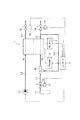
本発明は、例えば図1に示すように構成された第1実施形態に係る燃料電池システムに適用される。この燃料電池システムは、例えば車両に搭載され、当該車両の走行トルクを発生させる駆動モータ等の負荷に電力供給を行うと共に、蓄電池に電力を充電するものである。
[First Embodiment]
The present invention is applied to the fuel cell system according to the first embodiment configured as shown in FIG. 1, for example. This fuel cell system is mounted on a vehicle, for example, and supplies power to a load such as a drive motor that generates a running torque of the vehicle and charges the storage battery with power.
[燃料電池システムの構成]
この燃料電池システムは、図1に示すように、燃料ガス及び酸化剤ガスが供給されることにより発電する燃料電池スタック1を備える。この燃料電池スタック1は、例えば、固体高分子電解質を挟んで水素極1aと空気極1bとを対設した燃料電池セル構造体が複数積層して構成されている。本例においては、燃料電池スタック1が電気化学反応を発生させるための燃料ガスとして水素ガスを水素極1aに供給すると共に、酸化剤ガスとして酸素を含む空気を空気極1bに供給する燃料電池システムについて説明する。
[Configuration of fuel cell system]
As shown in FIG. 1, the fuel cell system includes a
この燃料電池システムは、燃料電池スタック1に空気を供給して排出する空気系、燃料電池スタック1に水素ガスを供給させる水素ガス系を備える。なお、本例においては燃料電池スタック1を加湿する加湿用純水を循環させる加湿用純水系、燃料電池スタック1の温度調整をする冷却水を循環させる冷却水系の図示を省略している。この燃料電池システムでは、燃料電池スタック1の発電を制御するに際して、水素ガス系及び空気系の各部をコントローラ2により制御する。
The fuel cell system includes an air system for supplying and discharging air to the
水素ガス系は、燃料電池スタック1の水素ガス入口に接続された水素供給流路L1に、水素ボンベ11、水素圧力調整弁12及びアクチュエータ13が設けられ、燃料電池スタック1の水素ガス出口に接続された水素排出流路L2に、パージ弁14及びアクチュエータ15が設けられて構成されている。
The hydrogen gas system is provided with a
この水素ガス系は、燃料電池システムの通常運転時において、水素ボンベ11に貯蔵した高圧水素を水素ガスとして水素極1aに導く。このとき、水素ガス系は、コントローラ2によりアクチュエータ13が駆動されて、水素圧力調整弁12の開度が調整される。これにより、水素ガスは、水素圧力調整弁12によって適正な圧力に調圧制御されて、水素極1aに導入される。なお、コントローラ2は、水素極1a内のガス圧力を検出するアノード極内圧力センサ(図示せず)の検出値を参照して、所望の圧力となるように水素圧力調整弁12の開度調整を行う。
This hydrogen gas system guides high-pressure hydrogen stored in the
また、この水素ガス系は、水素極1a内に水素ガス以外の不純物が蓄積した場合に、パージ弁14を開状態とするようにアクチュエータ15を駆動することにより、水素ガスと共に不純物を外気に放出する。
Further, this hydrogen gas system releases impurities together with hydrogen gas to the outside air by driving the
このような水素ガス系は、燃料電池システムの起動時に、水素供給流路L1、水素極1aのガスを水素で置換するために、後述の空気系により空気を空気極1bに供給しない状態で、水素ガスのみを水素極1aに供給するように制御される。
In such a hydrogen gas system, in order to replace the gas in the hydrogen supply flow path L1 and the
空気系は、空気極1bの空気入口と接続された空気供給流路L3にコンプレッサ21が設けられ、空気極1bの空気出口と接続された空気排出流路L4に空気調圧弁22及びアクチュエータ23が設けられて構成されている。
In the air system, a
この空気系は、燃料電池システムの通常運転時において、コントローラ2によりコンプレッサ21のコンプレッサモータ(図示せず)の回転数が制御され、外気を取り込んで圧縮空気として空気極1bの空気入口に導入する。このとき、コントローラ2は、図示しない空気圧力センサの検出値を参照して、空気極1b内の空気圧力を所望の圧力値とするようにアクチュエータ23を駆動して、空気調圧弁22の開度調整を行う。そして、燃料電池スタック1の空気出口から排出された空気は、空気排出流路L4及び空気調圧弁22を通過して、外気に排出される。
In the air system, during the normal operation of the fuel cell system, the rotation speed of the compressor motor (not shown) of the
このような空気系は、燃料電池システムの起動時に、水素供給流路L1及び水素極1aに定常的に水素ガスが流れるようになるように、空気を空気極1bに供給しない状態とされる。
Such an air system is in a state in which air is not supplied to the
更に、この燃料電池システムは、燃料電池スタック1の発電電圧を検出する電圧センサ3及び上述の駆動モータ等の負荷とは別個に設けられた予備負荷4を備える。
Further, the fuel cell system includes a
電圧センサ3は、燃料電池スタック1の発電電圧を検出し、当該発電電圧がセンサ信号としてコントローラ2に読み込まれる。このセンサ信号は、コントローラ2により燃料電池スタック1の発電量を制御する場合や、燃料電池スタック1の状態を監視するために使用される。
The
予備負荷4は、燃料電池システムの起動時であって、水素ガスの供給開始時に発生する発電電力を消費するために備えられる。この予備負荷4は、例えばダミー抵抗と開閉器とからなり、コントローラ2により開閉器が開状態(開放状態)とされている場合には発電電力をダミー抵抗で消費させず、コントローラ2により開閉器が閉状態(導通状態)とされている場合には発電電力をダミー抵抗で消費させる。このような予備負荷4は、燃料電池システムの起動時において、コントローラ2により開閉器が閉状態とされ、燃料電池スタック1のカソード触媒腐食劣化抑制を招く高電圧が印加される。なお、この予備負荷4は、固定抵抗値のものや可変抵抗のものを使用しても良く、要するに燃料電池スタック1の発電電圧を、カソード電極触媒の腐食を発生させない所定値以下とするものであれば良い。
The
コントローラ2は、後述する燃料電池システムの起動処理等を行う手順を実行するCPU(Central Processing Unit)や、上述した各部とのインターフェース回路等からなる。このコントローラ2は、例えば外部からの燃料電池システムの起動命令、更には車両用駆動モータに要求される駆動トルクに従って、上述した各部を制御する。
The
[燃料電池システムの起動処理]
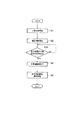
つぎに、上述したように構成された燃料電池システムの起動処理について、図2のフローチャート及び図3のタイミングチャートを参照して説明する。
[Startup process of fuel cell system]
Next, the startup process of the fuel cell system configured as described above will be described with reference to the flowchart of FIG. 2 and the timing chart of FIG.
この起動処理は、例えば車両のIGNスイッチが運転者にオン操作されることにより、コントローラ2に燃料電池システムの起動命令が入力されることに応じて、ステップS1以降の処理を開始する。
In this activation process, for example, when the driver turns on the IGN switch of the vehicle, a process for starting the fuel cell system is input to the
先ずステップS1において、コントローラ2は、コンプレッサ21を停止状態に維持したままにすることにより空気極1bへの空気供給を遮断した状態で、水素極1aへの水素供給量が一定になるように水素圧力調整弁12の開度を調整する。このとき、コントローラ2は、パージ弁14を所定開度で開状態とするようにアクチュエータ15を制御しておく。これに対し、燃料電池システムは、時刻t1にて水素極1aへの水素ガスの供給が開始され、時刻t12にて水素ガス流量が所定流量まで立ち上がる(図3(b))。
First, in step S1, the
これにより、水素ガスは水素ボンベ11から水素圧力調整弁12を介して水素極1aに導入され、水素供給流路L1及び水素極1aに存在していた残留ガスは、外部に排出開始される。
Thereby, hydrogen gas is introduced into the
このステップS1おいては、コンプレッサ21を停止状態としているために空気極1bに空気供給を行っていないが(図3(a))、燃料電池システムの停止期間において空気極1b内に酸素が残存していることにより、時刻t1から供給開始した水素ガスと残存していた酸素とを使用した電気化学反応が開始されて、時刻t1から発電電圧(図3(c))が立ち上がる。この発電電圧の立ち上がりは、電圧センサ3で検出され、コントローラ2で認識される。
In step S1, air is not supplied to the
このように水素ガスの供給を開始した場合、水素極1aの残留ガス(空気)の分子量(ガス密度)が水素ガスの分子量よりも高い(例えば約14倍)ので、パージ弁14から残留ガスが排出されにくい状態となっている。したがって、水素極1aへの水素ガス供給流量に対して残留ガスの排出流量が少なく、水素極1a内の圧力は高くなり(図3(e))、パージ弁14からは、先ず水素よりも残留ガスが先に排出される状態となり、次第に水素ガスと残留ガスとの混合ガスが排出され始める。
When supply of hydrogen gas is started in this way, the molecular weight (gas density) of the residual gas (air) of the
次にコントローラ2は、ステップS2において、ステップS1で立ち上がった発電電圧を抑制する動作を行う。このとき、コントローラ2は、水素極1a及び空気極1bの電極と予備負荷4とを導通させ、燃料電池スタック1の発電電圧を予備負荷4に印加することで、予備負荷4に電流を供給させる。また、コントローラ2は、電圧センサ3により検出している現在の発電電圧が、カソード電極触媒の腐食を進行させるような所定値以上となった場合に、燃料電池スタック1と予備負荷4とを導通させても良い。
Next, the
これにより、時刻t1から僅かに遅れた時刻t2から予備負荷4に発電電流が流れ始めて、発電電流がピーク値まで上昇すると(図3(d))、発電電圧が低下し始める(図3(c))。このように発電電圧が低下すると、カソード電極触媒の腐食が進行するためのエネルギーが抑制されることになる。
As a result, the generated current starts to flow to the
このように、ステップS1及びステップS2の処理を行った後には、残留ガスが排出されて、パージ弁14から排出されるガスが水素リッチとなるほど、すなわち水素極1a内の水素濃度が高くなるほど、時刻t3以降に示すように水素極1a内のガス圧力が低くなる。
As described above, after the processing of Step S1 and Step S2, the residual gas is discharged, and the gas discharged from the
次にコントローラ2は、ステップS3において、水素極1a内のガス圧力を検出し、現在の水素極1a内のガス圧力に燃料電池スタック1の電気化学反応による補正を加えた水素極1a内のガス圧力が、所定値P2以下か否かを判定する。なお、このガス圧力の補正処理については、後述する。
Next, in step S3, the
そして、コントローラ2は、補正後の水素極1a内のガス圧力が所定値P2以下ではないと判定した場合には、この判定を繰り返し、補正後の圧力が所定値P2以下となったと判定した場合にはステップS4に処理を進める。
When the
そして、コントローラ2は、ステップS4において、水素極1a内の残留ガスを水素ガスで置換する動作が完了して終了したと時刻t5で判断し、ステップS5において、コンプレッサ21を駆動すると共に空気調圧弁22を開状態にするようにアクチュエータ23を制御して、空気極1bに空気の供給を開始して、例えば駆動モータの要求トルクに応じた水素量及び空気量を供給する通常発電に移行する(図3(a)、(b))。
Then, the
「ガス圧力の補正処理」
このステップS3において行う補正処理は、水素極1a内で電気化学反応によって消費される水素ガス量を考慮して、水素極1a内の水素ガスへの置換が完了したか否かを判定するための水素極1a内のガス圧力を補正する。
"Gas pressure correction process"
The correction process performed in step S3 is for determining whether or not the replacement with the hydrogen gas in the
仮に、ステップS1以降の水素ガスの供給開始後に電気化学反応によって水素が消費されないとすると、水素ボンベ11から水素極1aに供給した水素量と同量のガスをパージ弁14から排出する必要が生じる。このため、水素極1a内の圧力は、図3(e)の特性Bに示すように時間と共に変化し、水素極1aが水素ガスで置換完了されたときの水素極1aの圧力はP2となる。
If hydrogen is not consumed by an electrochemical reaction after the supply of hydrogen gas after step S1 is started, it is necessary to discharge from the
これに対し、空気極1b内に酸素が存在している状態で水素極1aに水素ガスの供給を開始した場合には、電気化学反応によって供給した水素ガスが消費され、パージ弁14から排出すべきガス量は少なくなる。このため、水素極1a内の圧力は、図3(e)の特性Aに示すように、特性Bよりも低い状態で時間と共に変化して、水素極1aが水素ガスで置換完了されたときの水素極1aの圧力は、P2よりも低いP1となる。
On the other hand, when the supply of hydrogen gas to the
したがって、電気化学反応によって消費される水素量を考慮せずにステップS3の所定値をP2に設定した場合には、実際の水素ガス圧力が特性Aに示すようになり、本例において水素ガスへの置換が完了したと判断する時刻t5よりも早い時刻t4となってしまう。 Therefore, when the predetermined value in step S3 is set to P2 without considering the amount of hydrogen consumed by the electrochemical reaction, the actual hydrogen gas pressure becomes as shown in the characteristic A. In this example, the hydrogen gas is changed to hydrogen gas. The time t4 is earlier than the time t5 at which it is determined that the replacement has been completed.
そこで、第1実施形態に係る燃料電池システムのコントローラ2は、図示しない電流センサによって例えば予備負荷4に流れる発電電流を監視し、当該発電電流値から水素ガスへの置換に寄与せずに電気化学反応によって消費された水素量を推定する。次にコントローラ2は、推定した消費した水素量と、現在パージ弁14から排出されている水素量とを加算した水素量をパージ弁14から排出するために必要な水素極1a内の圧力を推定し、当該推定した水素極1a内の圧力を所定値P2とする。このとき、コントローラ2は、例えばパージ弁14を通過する水素量を検出する流量センサ(図示せず)のセンサ信号を読み込んで、実際にパージ弁14から排出された水素量を求める。
Therefore, the
具体的には、コントローラ2は、パージ弁14を通過する体積流量を求める下記の式1に示すような演算式を用いる。

ここで、式1において、Qは体積流量、Aはパージ弁14の開口面積、ρ0はガス密度、κは比熱比、p0はパージ弁14の上流圧力、peはパージ弁14の下流圧力である。この式1において、κ、pe、ρ0は一定と仮定することができ、体積流量Qを発電電流に基づく消費された水素量とパージ弁14から排出されている水素量とを加算した水素量とすると、パージ弁14の上流圧力(水素極1aのガス圧力)p0を補正後の水素極1aのガス圧力として求めることができる。そして、コントローラ2は、式1により求めた補正後の水素極1aのガス圧力と、所定値P2とを比較することになる。
Here, in
[第1実施形態の効果]
以上詳細に説明したように、本発明を適用した第1実施形態に係る燃料電池システムによれば、空気極1bへ酸素を供給しない状態で、水素極1aに水素ガスを供給し、水素極1aの水素ガスへの置換が完了すると判断されるまで、空気極1bの残留酸素によって発生する発電電圧が所定値以下になるように予備負荷4を燃料電池スタック1に接続するので、カソード電極触媒の腐食を進行させるエネルギーを抑制することができると共に、水素極1a内が水素ガスに確実に置換したことを判断することができるので、通常発電に移行した後に水素極1a内の水素ガスが不足するという事態を回避することができる。
[Effect of the first embodiment]
As described above in detail, according to the fuel cell system according to the first embodiment to which the present invention is applied, hydrogen gas is supplied to the
また、この燃料電池システムによれば、システム起動時に、水素ガス流量を一定にしている場合、水素極1a内の残留ガスが水素ガスに置換されるに従って低くなる燃料電池スタック1内のガス圧力を、電気化学反応によって消費された水素量が置換に寄与しないものとして補正し、当該補正後のガス圧力と、電気化学反応による消費が発生しないと仮定した場合の水素ガスへの置換が完了したときの水素極1a内のガス圧力P2とを比較して、水素極1aの水素ガスへの置換が完了したか否かを判断するので、更に正確に水素極1a内の水素ガスへの置換を判断することができる。
Further, according to this fuel cell system, when the hydrogen gas flow rate is constant at the time of starting the system, the gas pressure in the
また、この燃料電池システムによれば、電気化学反応によって消費された水素量を実際の電流値から推定するので、システム起動毎に空気極1bの残留酸素量が変化する場合であって水素ガスを供給開始したときの発電量の立ち上がり方が変化する場合であっても、正確に水素極1a内が水素ガスに置換されたことを判断することができる。
Further, according to this fuel cell system, since the amount of hydrogen consumed by the electrochemical reaction is estimated from the actual current value, the amount of residual oxygen in the
また、この燃料電池システムによれば、前回の停止時刻からの経過時間が長い場合と短い場合とで、水素極1a内の水素ガスへの置換に要する水素量を調整することができ、例えば、空気極1bに残留酸素が少ない場合に余分な水素ガスを供給する必要なく、水素ガスが無駄となることを抑制することができる。
Further, according to this fuel cell system, the amount of hydrogen required for replacement with hydrogen gas in the
[第2実施形態]
つぎに、第2実施形態に係る燃料電池システムについて説明する。なお、上述の第1実施形態と同様の部分については同一符号を付することによりその詳細な説明を省略する。
[Second Embodiment]
Next, a fuel cell system according to a second embodiment will be described. In addition, about the part similar to the above-mentioned 1st Embodiment, the detailed description is abbreviate | omitted by attaching | subjecting the same code | symbol.
この第2実施形態に係る燃料電池システムは、システム起動時に、水素極1a内のガス圧力を一定にして水素ガスを供給するように水素圧力調整弁12の開度調整を行い、電気化学反応によって消費される水素量に応じて水素圧力調整弁12の開度を補正して水素極1aの水素ガスへの置換が完了したかを判断する点で、第1実施形態とは異なる。
The fuel cell system according to the second embodiment adjusts the opening of the hydrogen
この第2実施形態における起動処理を図4に示すように、コントローラ2は、先ずステップS11において、パージ弁14を開状態とし、空気極1bに空気を供給しない状態で(図5(a))、水素極1a内のガス圧力が一定となるように水素圧力調整弁12の開度を調整することにより、水素ガスを水素極1aに供給開始する。これにより、時刻t11にて水素極1aへの水素ガスの供給が開始され、時刻t12にて水素ガス流量が所定流量まで立ち上がり(図5(b))、水素供給流路L1及び水素極1aに存在していたガスは、外部に排出開始される。
As shown in FIG. 4 for the starting process in the second embodiment, the
そして、空気極1bの残留酸素と供給開始した水素ガスとを用いて電気化学反応が起こり、時刻t11から発電電圧(図5(c))が立ち上がり、ステップS2においては、燃料電池スタック1と予備負荷4とを導通させることにより、時刻t12から発電電流(図5(d))が立ち上がる。このとき、水素極1a内の多くの水素ガスが消費されるため、水素圧力調整弁12の開度を大きくする。
Then, an electrochemical reaction occurs using the residual oxygen in the
その後、パージ弁14の開度が一定である場合、水素極1aの残留ガス(空気)の分子量が水素ガスの分子量よりも高いので、パージ弁14から残留ガスが排出されにくいために水素極1a内のガス圧力が高くなる方向に作用するため、水素極1a内のガス圧力を一定とするためには、水素圧力調整弁12の開度を次第に小さくする必要がある。そして、水素極1a内の残留ガスが次第に少なくなって、水素ガス量が多くなると、パージ弁14から排出されるガス量が多くなり、時刻t13以降においては水素圧力調整弁12の開度を次第に大きくする(図5(e))。
Thereafter, when the opening degree of the
次にコントローラ2は、ステップS12において、現在の制御対象となっている水素圧力調整弁12の開度に燃料電池スタック1の電気化学反応による補正を加えた水素圧力調整弁12の開度が、所定値a2以上か否かを判定する。なお、この水素圧力調整弁12の開度の補正処理については、後述する。
Next, in step S12, the
そして、コントローラ2は、補正後の水素圧力調整弁12の開度が所定値a2以上ではないと判定した場合には、この判定を繰り返し、補正後の水素圧力調整弁12の開度が所定値a2以上となったと判定した場合にはステップS4に処理を進める。
When the
そして、コントローラ2は、ステップS4において、水素極1a内の残留ガスを水素ガスで置換する動作が完了して終了したと時刻t15で判断し、ステップS5において、空気極1bに空気の供給を開始して、例えば駆動モータの要求トルクに応じた水素量及び空気量を供給する通常発電に移行する(図5(a)、(b))。
Then, the
「水素圧力調整弁12の開度の補正処理」
ステップS12において行う補正処理は、水素極1a内で電気化学反応によって消費される水素ガス量を考慮して、水素極1a内の水素ガスへの置換が完了したか否かを判定するための水素圧力調整弁12の開度を補正する。
“Adjustment of the opening of the hydrogen
The correction process performed in step S12 is hydrogen for determining whether or not the replacement with the hydrogen gas in the
仮に、ステップS11以降の水素ガス圧力を一定にした場合に、電気化学反応によって水素が消費されないとすると、水素極1a内の残留ガスの分子量が水素ガスの分子量よりも高いので、供給する必要がある水素供給量が少なくなる。このとき、水素極圧力が一定のため、重たいガスを排出するときは、供給水素量も少なくなる必要があり、水素圧力調整弁12の開度は、図5(e)の特性Dに示すように時間と共に変化し、水素極1aが水素ガスで置換完了されたときの水素圧力調整弁12の開度はa2となる。
If the hydrogen gas pressure after step S11 is kept constant, if the hydrogen is not consumed by the electrochemical reaction, the molecular weight of the residual gas in the
これに対し、電気化学反応によって供給した水素ガスが消費される場合には、水素極1a内のガス圧力を一定とするためには水素極1aに供給する水素ガス量を多くする必要があるため、水素圧力調整弁12の開度は、図5(e)の特性Cに示すように、電気化学反応が発生した場合には大きくする必要があるので特性Dよりも大きくなり、水素極1aが水素ガスで置換完了されたときの水素圧力調整弁12の開度はa2よりも大きいa1となる。
On the other hand, when the hydrogen gas supplied by the electrochemical reaction is consumed, it is necessary to increase the amount of hydrogen gas supplied to the
したがって、電気化学反応によって消費される水素量を考慮せずにステップS12の所定値をa2に設定した場合には、実際の水素圧力調整弁12の開度が特性Cに示すようになり、本例において水素ガスへの置換が完了したと判断する時刻t15よりも早い時刻t14となってしまう。
Therefore, when the predetermined value in step S12 is set to a2 without considering the amount of hydrogen consumed by the electrochemical reaction, the actual opening degree of the hydrogen
そこで、第2実施形態に係る燃料電池システムのコントローラ2は、実際の水素圧力調整弁12の開度から水素供給量を推定すると共に、置換に寄与しない電気化学反応によって消費された水素量を発電電流から推定する。そしてコントローラ2は、推定した水素供給量から、推定した消費された水素量を差し引いた水素量を、水素極1aに供給するために必要な水素圧力調整弁12の開度a2を推定する。
Therefore, the
具体的には、コントローラ2は、水素圧力調整弁12を通過する体積流量を求める上記式1に示すような演算式を用いる。ここで、上記式1におけるAは、水素圧力調整弁12の開口面積とし、p0は水素圧力調整弁12の上流圧力、peは水素圧力調整弁12の下流圧力(水素極1a内の一定ガス圧力)とする。そして、この式1において、κ、pe、ρ0は一定と仮定することができ、予め水素ボンベ11の仕様等により既知のp0を用いて、体積流量Qを、推定した水素供給量から推定した消費された水素量を差し引いた水素量とすると、Aを特性Dのような変化として求めることができる。そして、コントローラ2は、式1により求めた補正後の水素圧力調整弁12の開度と、所定値a2とを比較することになる。
Specifically, the
[第2実施形態の効果]
以上詳細に説明したように、本発明を適用した第2実施形態に係る燃料電池システムによれば、システム起動時に、水素極1a内のガス圧力を一定にしている場合、水素極1a内の残留ガスが水素ガスに置換されるに従って大きくなる水素圧力調整弁12の開度を、電気化学反応によって消費された水素量が置換に寄与しないものとして補正し、当該補正後の水素圧力調整弁12の開度と、電気化学反応による消費が発生しないと仮定した場合の水素ガスへの置換が完了したときの水素圧力調整弁12の開度a2とを比較して、水素極1aの水素ガスへの置換が完了したか否かを判断するので、正確に水素極1a内の水素ガスへの置換を判断することができる。
[Effects of Second Embodiment]
As described above in detail, according to the fuel cell system according to the second embodiment to which the present invention is applied, when the gas pressure in the
すなわち、この燃料電池システムによれば、水素ガスを供給開始したときの発電量の立ち上がり方が変化する場合であっても、正確に水素極1a内が水素ガスに置換されたことを判断することができ、水素ガスの無駄な排出、置換が完了したと判断した時の水素ガス不足及びカソード電極触媒の腐食を回避することができる。
That is, according to this fuel cell system, it is possible to accurately determine that the interior of the
[第3実施形態]
つぎに、第3実施形態に係る燃料電池システムについて説明する。なお、上述の実施形態と同様の部分については同一符号を付することによりその詳細な説明を省略する。
[Third Embodiment]
Next, a fuel cell system according to a third embodiment will be described. Note that parts similar to those in the above-described embodiment are denoted by the same reference numerals, and detailed description thereof is omitted.
第3実施形態に係る燃料電池システムは、図6に示すように、燃料電池スタック1の水素ガス出口から分岐し、当該水素ガス出口から排出された水素ガスを水素ガス入口に循環させる水素循環流路L11を設け、当該水素循環流路L11と水素供給流路L1との合流点にエゼクタポンプ31を設けた点で、上述した第1実施形態とは異なる。
As shown in FIG. 6, the fuel cell system according to the third embodiment branches from the hydrogen gas outlet of the
このような燃料電池システムは、システム起動時に、コントローラ2により第1実施形態と同様に図2の処理を行い、図3に示すような動作を行う。ここで、ステップS1においては、水素圧力調整弁12を通過させる水素ガス流量と水素循環流路L11からエゼクタポンプ31に導入される水素ガス流量とを加算した水素ガス流量が一定となるように水素圧力調整弁12の開度を調整する。このとき、コントローラ2は、水素ボンベ11からエゼクタポンプ31に流す水素ガスの流速に応じた、水素循環流路L11からエゼクタポンプ31に取り込まれて水素極1aに導入される水素流量をエゼクタポンプ31の特性等に基づいて予め記憶しており、当該循環された水素流量と水素ボンベ11から水素極1aに直接導入する水素流量との和を一定とするように水素圧力調整弁12の開度を調整する。
Such a fuel cell system performs the process shown in FIG. 2 by the
このような第3実施形態に係る燃料電池システムによれば、システムの起動時に、水素ガスをエゼクタポンプ31によって循環させて燃料電池スタック1に供給している場合に、燃料電池スタック1から排出されて再度燃料電池スタック1に循環される水素ガス量を考慮して、水素極1a内の水素ガスへの置換を判断する水素ガス圧力を水素極1aで消費した水素量によって補正するので、システムの状態によって発電電圧の立ち上がり方が異なる場合であっても、正確に水素極1aの水素ガスへの置換を行うことができる。
According to such a fuel cell system according to the third embodiment, when hydrogen gas is circulated by the
[第4実施形態]
つぎに、第4実施形態に係る燃料電池システムについて説明する。なお、上述の実施形態と同様の部分については同一符号を付することによりその詳細な説明を省略する。
[Fourth Embodiment]
Next, a fuel cell system according to a fourth embodiment will be described. Note that parts similar to those in the above-described embodiment are denoted by the same reference numerals, and detailed description thereof is omitted.
第4実施形態に係る燃料電池システムは、図6に示すように、燃料電池スタック1の水素ガス出口から分岐し、当該水素ガス出口から排出された水素ガスを水素ガス入口に循環させる水素循環流路L11を設け、当該水素循環流路L11と水素供給流路L1との合流点にエゼクタポンプ31を設けた点で、上述した第2実施形態とは異なる。
As shown in FIG. 6, the fuel cell system according to the fourth embodiment branches from a hydrogen gas outlet of the
このような燃料電池システムは、システム起動時に、コントローラ2により第1実施形態と同様に図4の処理を行い、図5に示すような動作を行う。ここで、ステップS11においては、水素極1a内のガス圧力を一定とするように水素圧力調整弁12の開度を調整し、ステップS2にて燃料電池スタック1と予備負荷4とを接続させた状態で、ステップS12で水素ボンベ11から直接水素極1aに導入する水素ガスとエゼクタポンプ31から循環させて水素極1aに導入する水素ガスとによって水素極1aの水素ガスへの置換が完了したか否かを判定する。
In such a fuel cell system, when the system is started, the
このとき、コントローラ2は、水素ボンベ11からエゼクタポンプ31に流す水素ガスの流速に応じた、水素循環流路L11からエゼクタポンプ31に取り込まれて水素極1aに導入される水素流量をエゼクタポンプ31の特性等に基づいて予め記憶しており、当該循環された水素流量と水素ボンベ11から水素極1aに直接導入する水素流量との和を水素極1aに導入した場合に、水素極1aのガス圧力を一定とするように水素圧力調整弁12の開度を調整する。
At this time, the
このような第4実施形態に係る燃料電池システムによれば、システムの起動時に、水素ガスをエゼクタポンプ31によって循環させて燃料電池スタック1に供給している場合に、燃料電池スタック1から排出されて再度燃料電池スタック1に循環される水素ガス量を考慮して、水素極1a内の水素ガスへの置換を判断する水素圧力調整弁12の開度を補正するので、システムの状態によって発電電圧の立ち上がり方が異なる場合であっても、正確に水素極1aの水素ガスへの置換を行うことができる。
According to such a fuel cell system according to the fourth embodiment, when hydrogen gas is circulated by the
[第5実施形態]
つぎに、第5実施形態に係る燃料電池システムについて説明する。なお、上述の実施形態と同様の部分については同一符号を付することによりその詳細な説明を省略する。
[Fifth Embodiment]
Next, a fuel cell system according to a fifth embodiment will be described. Note that parts similar to those in the above-described embodiment are denoted by the same reference numerals, and detailed description thereof is omitted.
この第5実施形態に係る燃料電池システムは、図6に示した構成であって、水素圧力調整弁12とエゼクタポンプ31との間のガス圧力を補正し、当該補正したガス圧力が以上となった場合に、水素極1aの水素ガスへの置換が完了したと判定する点で、上述した実施形態とは異なる。
The fuel cell system according to the fifth embodiment has the configuration shown in FIG. 6 and corrects the gas pressure between the hydrogen
この第5実施形態における起動処理を図7に示すように、コントローラ2は、先ずステップS11において、パージ弁14を開状態とし、空気極1bに空気を供給しない状態で(図8(a))、水素極1a内のガス圧力が一定となるように水素圧力調整弁12の開度を調整する。これにより、時刻t21にて水素極1aへの水素ガスの供給が開始され、時刻t22にて水素ガス流量が所定流量まで立ち上がり(図8(b))、水素供給流路L1及び水素極1aに存在していたガスは、外部に排出開始される。
As shown in FIG. 7 for the startup process in the fifth embodiment, the
そして、空気極1bの残留酸素と供給開始した水素ガスとを用いて電気化学反応が起こり、時刻t21から発電電圧(図8(c))が立ち上がり、ステップS2においては、燃料電池スタック1と予備負荷4とを導通させることにより、時刻t22から発電電流(図8(d))が立ち上がる。
Then, an electrochemical reaction occurs using the residual oxygen in the
そして、水素極1a内の残留ガスが次第に少なくなって、水素ガス量が多くなると、パージ弁14から排出されるガス量が多くなり、時刻t23以降においては水素圧力調整弁12の開度を次第に大きくすることにより、水素圧力調整弁12の下流のガス圧力が高くなる(図8(e))。
When the residual gas in the
次にコントローラ2は、ステップS21において、現在の水素圧力調整弁12の下流のガス圧力に燃料電池スタック1の電気化学反応による補正を加えた水素圧力調整弁12の下流のガス圧力が、所定値P4以上か否かを判定する。なお、この水素圧力調整弁12の下流のガス圧力の補正処理については後述する。また、このステップS21においては、水素圧力調整弁12の下流のガス圧力を検出する圧力センサ(図示せず)からのセンサ信号をコントローラ2により読み込むものとする。
Next, in step S <b> 21, the
そして、コントローラ2は、補正後の水素圧力調整弁12の下流のガス圧力が所定値P4以上ではないと判定した場合には、この判定を繰り返し、補正後の水素圧力調整弁12の下流のガス圧力が所定値P4以上となったと判定した場合にはステップS4に処理を進める。
If the
そして、コントローラ2は、ステップS4において、水素極1a内の残留ガスを水素ガスで置換する動作が完了して終了したと時刻t25で判断し、ステップS5において、空気極1bに空気の供給を開始して、例えば駆動モータの要求トルクに応じた水素量及び空気量を供給する通常発電に移行する(図8(a)、(b))。
Then, the
「水素圧力調整弁12の下流のガス圧力の補正処理」
ステップS21において行う補正処理は、水素極1a内で電気化学反応によって消費される水素ガス量を考慮して、水素極1a内の水素ガスへの置換が完了したか否かを判定するための水素圧力調整弁12の下流のガス圧力を補正する。
“Correction of gas pressure downstream of hydrogen
The correction process performed in step S21 is a hydrogen for determining whether or not the replacement with the hydrogen gas in the
仮に、ステップS1以降の水素ガス圧力を一定にした場合に、電気化学反応によって水素が消費されないとすると、水素極1a内の残留ガスの分子量が水素ガスの分子量よりも高いので、供給する必要がある水素供給量が少なくなる。このとき、水素極圧力が一定のため、重たいガスを排出するときは、供給水素量も少なくなる必要があり、水素圧力調整弁12の下流のガス圧力は、図8(e)の特性Fに示すように時間と共に変化し、水素極1aが水素ガスで置換完了されたときの水素圧力調整弁12の下流のガス圧力はP4となる。
If the hydrogen gas pressure after step S1 is kept constant, if the hydrogen is not consumed by the electrochemical reaction, the molecular weight of the residual gas in the
これに対し、電気化学反応によって供給した水素ガスが消費される場合には、水素極1a内のガス圧力を一定とするためには水素極1aに供給する水素ガス量を多くする必要があるため、水素圧力調整弁12の下流のガス圧力は、図8(e)の特性Eに示すように、電気化学反応が発生した場合には大きくする必要があるので特性Fよりも大きくなり、水素極1aが水素ガスで置換完了されたときの水素圧力調整弁12の下流のガス圧力はP4よりも大きいP3となる。
On the other hand, when the hydrogen gas supplied by the electrochemical reaction is consumed, it is necessary to increase the amount of hydrogen gas supplied to the
したがって、電気化学反応によって消費される水素量を考慮せずにステップS21の所定値をP4に設定した場合には、実際の水素圧力調整弁12の下流のガス圧力が特性Eに示すようになり、本例において水素ガスへの置換が完了したと判断する時刻t25よりも早い時刻t24となってしまう。
Therefore, when the predetermined value in step S21 is set to P4 without considering the amount of hydrogen consumed by the electrochemical reaction, the actual gas pressure downstream of the hydrogen
そこで、第5実施形態に係る燃料電池システムのコントローラ2は、実際の水素圧力調整弁12の下流のガス圧力から水素供給量を推定すると共に、置換に寄与しない電気化学反応によって消費された水素量を発電電流から推定する。そしてコントローラ2は、推定した水素供給量から、推定した消費された水素量を差し引いた水素量を、水素極1aに供給するために必要な水素圧力調整弁12の下流のガス圧力を推定する。
Therefore, the
具体的には、コントローラ2は、水素圧力調整弁12を通過する体積流量を求める上記式1に示すような演算式を用いて、第2実施形態と同様な演算を行うことにより、補正後の水素圧力調整弁12の下流のガス圧力を求めて、所定値P4と比較することになる。
Specifically, the
[第5実施形態の効果]
以上詳細に説明したように、本発明を適用した第5実施形態に係る燃料電池システムによれば、システム起動時に、水素極1aのガス圧力を一定にしている場合、水素極1aが水素ガスへ置換されるに従って減少する水素圧力調整弁12の下流のガス圧力を電気化学反応によって消費される水素量を考慮して補正するので、正確に水素極1aの水素ガスへの置換を判断することができる。
[Effect of Fifth Embodiment]
As described above in detail, according to the fuel cell system according to the fifth embodiment to which the present invention is applied, when the gas pressure of the
[第6実施形態]
つぎに、第6実施形態に係る燃料電池システムについて説明する。なお、上述の実施形態と同様の部分については同一符号を付することによりその詳細な説明を省略する。
[Sixth Embodiment]
Next, a fuel cell system according to the sixth embodiment will be described. Note that parts similar to those in the above-described embodiment are denoted by the same reference numerals, and detailed description thereof is omitted.
この第6実施形態に係る燃料電池システムは、燃料電池スタック1の電気化学反応によって発生する生成水が水素極1aのガスに含まれることによって、水素極1aのガスのうち水素が含まれる密度が変化することを考慮して、水素極1aが水素ガスに置換されたかを判断する点で、上述した実施形態とは異なる。
In the fuel cell system according to the sixth embodiment, the generated water generated by the electrochemical reaction of the
上述したように、水素圧力調整弁12やパージ弁14を通過するガスの体積流量は、式1で表されるが、ガス密度ρ0が変化した場合にガスの体積流量が変化する。ここで、燃料電池スタック1から排出されるガスには、燃料電池スタック1の電気化学反応によって発生した生成水が水蒸気として含まれており、パージ弁14から排出されるガスの水蒸気含有量によって残留ガス及び水素ガスの排出量が異なる。また、燃料電池スタック1から排出されるガスの水蒸気含有量は、燃料電池スタック1の温度が高いほど、ガスの飽和水蒸気圧が増加するため、増加する。
As described above, the volume flow rate of the gas passing through the hydrogen
したがって、この第6実施形態に係る燃料電池システムは、水素流量を一定にしてシステムを起動するときに、水素極1aの水素ガスへの置換が完了したと判断する水素極1aのガス圧力P2を補正する。
Therefore, in the fuel cell system according to the sixth embodiment, when the system is started with a constant hydrogen flow rate, the gas pressure P2 of the
すなわち、コントローラ2は、電気化学反応によって消費された水素量と現在パージ弁14から排出されている水素量とを加算した水素量を、パージ弁14から排出するために必要な水素極1a内の圧力を推定するに際して、現在パージ弁14から排出されている水素量を燃料電池スタック1の温度に応じて補正する。このとき、コントローラ2は、燃料電池スタック1の温度センサ(図示せず)により検出された温度値から、水素極1aから排出されるガスの水蒸気量を推定する。そして、コントローラ2は、水素の分子量、残留ガス(空気)の分子量、水蒸気の分子量との比から、現在パージ弁14から排出されている水素量を補正することにより、当該補正した水素量と電気化学反応によって消費された水素量とを加算した水素量を、パージ弁14から排出するための水素極1a内の圧力を補正する。
That is, the
このような燃料電池システムによれば、水素極1aから排出されるガスが水蒸気飽和状態となっていても、燃料電池スタック1の温度が高くなるほど、パージ弁14から排出ガス中に含まれる水分濃度を低くして、水素極1aの水素ガスへの置換が完了したと判断する水素極1aのガス圧力を補正するので、より正確に水素極1aが水素ガスに置換されたことを判断することができる。
According to such a fuel cell system, even if the gas discharged from the
また、この第6実施形態に係る燃料電池システムは、水素極1aのガス圧力を一定にしてシステムを起動するときに、水素極1aのガス圧力への置換が完了したと判断する水素圧力調整弁12の開度a2を補正する。
Further, the fuel cell system according to the sixth embodiment has a hydrogen pressure regulating valve that determines that the replacement with the gas pressure of the
すなわち、コントローラ2は、実際の水素圧力調整弁12の開度から推定した水素供給量から消費された水素量を差し引いた水素量を、水素極1aに供給するために必要な水素圧力調整弁12の開度a2を推定するに際して、実際の水素圧力調整弁12の開度から推定した水素供給量を、燃料電池スタック1の温度によって決定される水蒸気量に基づいて補正する。これにより、コントローラ2は、水蒸気量に基づいて補正した水素供給量と、電気化学反応によって消費されている水素量とから、水素圧力調整弁12の開度a2を補正する。
That is, the
このような燃料電池システムによれば、水素極1aから排出されるガスが水蒸気飽和状態となっていて水素極1aへの水素供給量が変化する場合であっても、水素極1a内の水蒸気量に基づいて水素圧力調整弁12の開度を補正するので、より正確に水素極1aが水素ガスに置換されたことを判断することができる。
According to such a fuel cell system, even when the gas discharged from the
更に、この第6実施形態に係る燃料電池システムは、水素圧力調整弁12とエゼクタポンプ31との間のガス圧力を一定にしてシステムを起動するときに、水素極1aの水素ガスへの置換が進行するほど、圧力調整弁12とエゼクタポンプ31との間のガス圧力を大きくする場合に、水素極1aの水蒸気量によって圧力調整弁12とエゼクタポンプ31との間のガス圧力を補正する。これにより、燃料電池システムは、より正確に水素極1aが水素ガスに置換されたことを判断することができる。
Further, in the fuel cell system according to the sixth embodiment, the
なお、上述の実施の形態は本発明の一例である。このため、本発明は、上述の実施形態に限定されることはなく、この実施の形態以外であっても、本発明に係る技術的思想を逸脱しない範囲であれば、設計等に応じて種々の変更が可能であることは勿論である。 The above-described embodiment is an example of the present invention. For this reason, the present invention is not limited to the above-described embodiment, and various modifications can be made depending on the design and the like as long as the technical idea according to the present invention is not deviated from this embodiment. Of course, it is possible to change.
1 燃料電池スタック
2 コントローラ
3 電圧センサ
4 予備負荷
11 水素ボンベ
12 水素圧力調整弁
13,15,23 アクチュエータ
14 パージ弁
21 コンプレッサ
22 空気調圧弁
31 エゼクタポンプ
L1 水素供給流路
L2 水素排出流路
L3 空気供給流路
L4 空気排出流路
L11 水素循環流路
DESCRIPTION OF
Claims (9)
前記燃料電池の燃料ガス入口に接続された燃料ガス供給流路を介して前記燃料電池の燃料極に燃料ガスを供給し、前記燃料電池の燃料ガス出口に接続された燃料ガス排出流路を介して前記燃料電池から排出された燃料ガスを排出する燃料ガス供給手段と、
前記燃料電池の酸化剤ガス入口に接続された酸化剤ガス供給流路を介して前記燃料電池の酸化剤ガス極に酸化剤ガスを供給し、前記燃料電池の酸化剤ガス出口に接続された酸化剤ガス排出流路を介して前記燃料電池から排出された酸化剤ガスを排出する酸化剤ガス供給手段と、
前記燃料電池の発電電力を消費して、前記燃料電池の発電電圧を調整する電力消費手段と、
前記燃料電池の発電電圧を検出する発電電圧検出手段と、
システム起動時に、前記酸化剤極に酸化剤ガスを供給させない状態で、前記燃料極に燃料ガスを供給するように前記燃料ガス供給手段を制御し、前記燃料極が燃料ガスによって置換されたと判断するまで、前記発電電圧検出手段により検出されている燃料電池の発電電圧が所定値以下となるように前記電力消費手段で発電電圧を消費させる起動制御手段と
を備えることを特徴とする燃料電池システム。 A fuel cell that generates fuel by supplying fuel gas to the fuel electrode and supplying oxidant gas to the oxidant electrode; and
Fuel gas is supplied to the fuel electrode of the fuel cell via a fuel gas supply channel connected to the fuel gas inlet of the fuel cell, and via a fuel gas discharge channel connected to the fuel gas outlet of the fuel cell. Fuel gas supply means for discharging the fuel gas discharged from the fuel cell;
An oxidant gas is supplied to an oxidant gas electrode of the fuel cell via an oxidant gas supply channel connected to an oxidant gas inlet of the fuel cell, and an oxidant connected to an oxidant gas outlet of the fuel cell. An oxidant gas supply means for discharging the oxidant gas discharged from the fuel cell through the oxidant gas discharge channel;
Power consumption means for adjusting the power generation voltage of the fuel cell by consuming the power generated by the fuel cell;
Power generation voltage detection means for detecting the power generation voltage of the fuel cell;
At the time of starting the system, the fuel gas supply means is controlled to supply the fuel gas to the fuel electrode without supplying the oxidant gas to the oxidant electrode, and it is determined that the fuel electrode has been replaced by the fuel gas. And a start control means for consuming the generated voltage by the power consuming means so that the generated voltage of the fuel cell detected by the generated voltage detecting means is below a predetermined value.
前記起動制御手段は、前記燃料極に供給する燃料ガス流量が一定となるように可変絞り弁の開度を調整し、前記燃料極の実際のガス圧力を前記燃料電池の電気化学反応により消費された水素量に基づいて補正し、このガス圧力補正値が所定値以下となった場合に、前記燃料極が燃料ガスによって置換されたと判断することを特徴とする請求項1に記載の燃料電池システム。 The fuel gas supply means is provided with a variable throttle valve for adjusting a flow rate of the fuel gas flowing through the fuel gas supply flow path,
The activation control means adjusts the opening of the variable throttle valve so that the flow rate of the fuel gas supplied to the fuel electrode is constant, and the actual gas pressure of the fuel electrode is consumed by the electrochemical reaction of the fuel cell. 2. The fuel cell system according to claim 1, wherein the fuel electrode is determined to have been replaced with a fuel gas when the gas pressure correction value is equal to or less than a predetermined value. .
前記起動制御手段は、前記燃料極に供給する燃料ガス圧力が一定となるように可変絞り弁の開度を調整しているときに、前記可変絞り弁の実際の開度を前記燃料電池の電気化学反応により消費された水素量に基づいて補正し、この開度補正値が所定値以上となった場合に、前記燃料極が燃料ガスによって置換されたと判断することを特徴とする請求項1に記載の燃料電池システム。 The fuel gas supply means is provided with a variable throttle valve for adjusting a flow rate of the fuel gas flowing through the fuel gas supply flow path,
The activation control means adjusts the actual opening of the variable throttle valve to the electric power of the fuel cell when the opening of the variable throttle valve is adjusted so that the fuel gas pressure supplied to the fuel electrode is constant. The correction is made based on the amount of hydrogen consumed by the chemical reaction, and when the opening correction value is equal to or greater than a predetermined value, it is determined that the fuel electrode is replaced by fuel gas. The fuel cell system described.
前記起動制御手段は、前記燃料極に供給する燃料ガス流量が一定となるように可変絞り弁の開度を調整し、前記燃料極の実際のガス圧力を前記燃料電池の電気化学反応により消費された水素量に基づいて補正し、このガス圧力補正値が所定値以下となった場合に、前記燃料極が燃料ガスによって置換されたと判断することを特徴とする請求項1に記載の燃料電池システム。 The fuel gas supply means includes a variable throttle valve that adjusts the flow rate of the fuel gas flowing through the fuel gas supply flow path, and an ejector pump that circulates the fuel gas discharged from the fuel cell to the fuel gas supply flow path. ,
The activation control means adjusts the opening of the variable throttle valve so that the flow rate of the fuel gas supplied to the fuel electrode is constant, and the actual gas pressure of the fuel electrode is consumed by the electrochemical reaction of the fuel cell. 2. The fuel cell system according to claim 1, wherein the fuel electrode is determined to have been replaced with a fuel gas when the gas pressure correction value is equal to or less than a predetermined value. .
前記起動制御手段は、前記燃料極に供給する燃料ガス圧力が一定となるように可変絞り弁の開度を調整しているときに、前記可変絞り弁の実際の開度を前記燃料電池の電気化学反応により消費された水素量に基づいて補正し、この開度補正値が所定値以上となった場合に、前記燃料極が燃料ガスによって置換されたと判断することを特徴とする請求項1に記載の燃料電池システム。 The fuel gas supply means includes a variable throttle valve that adjusts the flow rate of the fuel gas flowing through the fuel gas supply flow path, and an ejector pump that circulates the fuel gas discharged from the fuel cell to the fuel gas supply flow path. ,
The activation control means adjusts the actual opening of the variable throttle valve to the electric power of the fuel cell when the opening of the variable throttle valve is adjusted so that the fuel gas pressure supplied to the fuel electrode is constant. The correction is made based on the amount of hydrogen consumed by the chemical reaction, and when the opening correction value is equal to or greater than a predetermined value, it is determined that the fuel electrode is replaced by fuel gas. The fuel cell system described.
前記起動制御手段は、前記燃料極に供給する燃料ガス圧力が一定となるように可変絞り弁の開度を調整しているときに、前記可変絞り弁と前記エゼクタポンプとの間の実際のガス圧力を前記燃料電池の電気化学反応により消費された水素量に基づいて補正し、このガス圧力補正値が所定値以上となった場合に、前記燃料極が燃料ガスによって置換されたと判断することを特徴とする請求項1に記載の燃料電池システム。 The fuel gas supply means is provided on a downstream side of the variable throttle valve for adjusting a flow rate of the fuel gas flowing in the fuel gas supply flow path, and the fuel gas discharged from the fuel cell is supplied to the fuel. With an ejector pump that circulates in the gas supply flow path,
The start control means adjusts the opening of the variable throttle valve so that the fuel gas pressure supplied to the fuel electrode is constant, and the actual gas between the variable throttle valve and the ejector pump Correcting the pressure based on the amount of hydrogen consumed by the electrochemical reaction of the fuel cell, and determining that the fuel electrode has been replaced by the fuel gas when the gas pressure correction value exceeds a predetermined value. The fuel cell system according to claim 1, wherein
The fuel cell system according to claim 6, wherein the activation control unit corrects a gas pressure between the variable throttle valve and the ejector pump based on a temperature of the fuel cell.
Priority Applications (1)
| Application Number | Priority Date | Filing Date | Title |
|---|---|---|---|
| JP2004042592A JP2005235546A (en) | 2004-02-19 | 2004-02-19 | Fuel cell system |
Applications Claiming Priority (1)
| Application Number | Priority Date | Filing Date | Title |
|---|---|---|---|
| JP2004042592A JP2005235546A (en) | 2004-02-19 | 2004-02-19 | Fuel cell system |
Publications (1)
| Publication Number | Publication Date |
|---|---|
| JP2005235546A true JP2005235546A (en) | 2005-09-02 |
Family
ID=35018279
Family Applications (1)
| Application Number | Title | Priority Date | Filing Date |
|---|---|---|---|
| JP2004042592A Pending JP2005235546A (en) | 2004-02-19 | 2004-02-19 | Fuel cell system |
Country Status (1)
| Country | Link |
|---|---|
| JP (1) | JP2005235546A (en) |
Cited By (6)
| Publication number | Priority date | Publication date | Assignee | Title |
|---|---|---|---|---|
| JP2008097973A (en) * | 2006-10-11 | 2008-04-24 | Toyota Motor Corp | Fuel cell system |
| WO2009119259A1 (en) * | 2008-03-25 | 2009-10-01 | トヨタ自動車株式会社 | Fuel cell system |
| JP2014044905A (en) * | 2012-08-28 | 2014-03-13 | Honda Motor Co Ltd | Starting method of fuel cell system and fuel cell system |
| JP2015084342A (en) * | 2015-02-02 | 2015-04-30 | 東芝燃料電池システム株式会社 | Fuel cell power generation system and method of supplying power to electric heater in fuel cell power generation system |
| CN112786922A (en) * | 2019-11-01 | 2021-05-11 | 株式会社东芝 | Fuel cell system and control method thereof |
| CN113851678A (en) * | 2021-09-07 | 2021-12-28 | 中车青岛四方机车车辆股份有限公司 | Hydrogen supply valve control method for hydrogen storage system, and hydrogen power system starting method and system |
-
2004
- 2004-02-19 JP JP2004042592A patent/JP2005235546A/en active Pending
Cited By (10)
| Publication number | Priority date | Publication date | Assignee | Title |
|---|---|---|---|---|
| JP2008097973A (en) * | 2006-10-11 | 2008-04-24 | Toyota Motor Corp | Fuel cell system |
| WO2009119259A1 (en) * | 2008-03-25 | 2009-10-01 | トヨタ自動車株式会社 | Fuel cell system |
| US9017888B2 (en) | 2008-03-25 | 2015-04-28 | Toyota Jidosha Kabushiki Kaisha | Fuel cell system |
| JP2014044905A (en) * | 2012-08-28 | 2014-03-13 | Honda Motor Co Ltd | Starting method of fuel cell system and fuel cell system |
| US10109872B2 (en) | 2012-08-28 | 2018-10-23 | Honda Motor Co., Ltd. | Fuel cell system activation method and fuel cell system |
| JP2015084342A (en) * | 2015-02-02 | 2015-04-30 | 東芝燃料電池システム株式会社 | Fuel cell power generation system and method of supplying power to electric heater in fuel cell power generation system |
| CN112786922A (en) * | 2019-11-01 | 2021-05-11 | 株式会社东芝 | Fuel cell system and control method thereof |
| CN112786922B (en) * | 2019-11-01 | 2024-04-26 | 株式会社东芝 | Fuel cell system and control method thereof |
| CN113851678A (en) * | 2021-09-07 | 2021-12-28 | 中车青岛四方机车车辆股份有限公司 | Hydrogen supply valve control method for hydrogen storage system, and hydrogen power system starting method and system |
| CN113851678B (en) * | 2021-09-07 | 2023-02-03 | 中车青岛四方机车车辆股份有限公司 | Hydrogen supply valve control method for hydrogen storage system, and hydrogen power system starting method and system |
Similar Documents
| Publication | Publication Date | Title |
|---|---|---|
| JP4868251B2 (en) | Fuel cell system, anode gas generation amount estimation device, and anode gas generation amount estimation method | |
| JP4507584B2 (en) | Fuel cell system | |
| JP4923551B2 (en) | Fuel cell system | |
| JP2009054553A (en) | Fuel cell system and its control method | |
| JP2009026736A (en) | Fuel cell system | |
| JP2009277502A (en) | Fuel cell system | |
| JP2010086939A (en) | Fuel cell system, and control method of fuel cell system | |
| US9812718B2 (en) | Fuel cell system | |
| JP2007103178A (en) | Fuel cell system | |
| US20150004512A1 (en) | Fuel cell system | |
| JP5858138B2 (en) | FUEL CELL SYSTEM AND CONTROL METHOD FOR FUEL CELL SYSTEM | |
| JP2007048519A (en) | Fuel cell system | |
| WO2013129553A1 (en) | Fuel cell system and control method for fuel cell system | |
| JP2007157587A (en) | Fuel cell system | |
| JP5239201B2 (en) | Fuel cell system and impurity discharge method in fuel cell system | |
| JP2007220355A (en) | Low-temperature starting method of fuel cell system and fuel cell | |
| US9059438B2 (en) | Fuel cell system | |
| JP4372523B2 (en) | Fuel cell control device | |
| JP2005116402A (en) | Starting method of fuel cell system | |
| JP2007311304A (en) | Fuel cell system | |
| JP2007026843A (en) | Fuel cell powered vehicle and its control method | |
| JP2005235546A (en) | Fuel cell system | |
| JP2009129760A (en) | Fuel cell system and control method of fuel cell system | |
| US9960440B2 (en) | Fuel cell system and control method for fuel cell system | |
| JP2006351336A (en) | Operation method of fuel cell, and fuel cell system |