JP2005228551A - Lighting control device - Google Patents
Lighting control device Download PDFInfo
- Publication number
- JP2005228551A JP2005228551A JP2004034781A JP2004034781A JP2005228551A JP 2005228551 A JP2005228551 A JP 2005228551A JP 2004034781 A JP2004034781 A JP 2004034781A JP 2004034781 A JP2004034781 A JP 2004034781A JP 2005228551 A JP2005228551 A JP 2005228551A
- Authority
- JP
- Japan
- Prior art keywords
- power
- light
- control
- terminal
- output
- Prior art date
- Legal status (The legal status is an assumption and is not a legal conclusion. Google has not performed a legal analysis and makes no representation as to the accuracy of the status listed.)
- Pending
Links
- 238000005286 illumination Methods 0.000 claims description 15
- 239000003086 colorant Substances 0.000 claims description 7
- 238000000034 method Methods 0.000 description 10
- 239000011347 resin Substances 0.000 description 8
- 229920005989 resin Polymers 0.000 description 8
- 230000003111 delayed effect Effects 0.000 description 4
- 238000010586 diagram Methods 0.000 description 3
- 239000003205 fragrance Substances 0.000 description 3
- 239000011521 glass Substances 0.000 description 3
- 239000000463 material Substances 0.000 description 3
- 239000000654 additive Substances 0.000 description 2
- 230000000996 additive effect Effects 0.000 description 2
- 229920000089 Cyclic olefin copolymer Polymers 0.000 description 1
- NIXOWILDQLNWCW-UHFFFAOYSA-N acrylic acid group Chemical group C(C=C)(=O)O NIXOWILDQLNWCW-UHFFFAOYSA-N 0.000 description 1
- 239000002386 air freshener Substances 0.000 description 1
- 229910052782 aluminium Inorganic materials 0.000 description 1
- XAGFODPZIPBFFR-UHFFFAOYSA-N aluminium Chemical compound [Al] XAGFODPZIPBFFR-UHFFFAOYSA-N 0.000 description 1
- 230000005540 biological transmission Effects 0.000 description 1
- 230000000694 effects Effects 0.000 description 1
- 238000005516 engineering process Methods 0.000 description 1
- 239000010408 film Substances 0.000 description 1
- PCHJSUWPFVWCPO-UHFFFAOYSA-N gold Chemical compound [Au] PCHJSUWPFVWCPO-UHFFFAOYSA-N 0.000 description 1
- 229910052737 gold Inorganic materials 0.000 description 1
- 239000010931 gold Substances 0.000 description 1
- 229910052751 metal Inorganic materials 0.000 description 1
- 239000002184 metal Substances 0.000 description 1
- 238000000465 moulding Methods 0.000 description 1
- 230000003287 optical effect Effects 0.000 description 1
- 239000003973 paint Substances 0.000 description 1
- 230000002093 peripheral effect Effects 0.000 description 1
- 229920000515 polycarbonate Polymers 0.000 description 1
- 239000004417 polycarbonate Substances 0.000 description 1
- 238000007639 printing Methods 0.000 description 1
- 239000010409 thin film Substances 0.000 description 1
- 238000002834 transmittance Methods 0.000 description 1
- 238000001771 vacuum deposition Methods 0.000 description 1
Images

Classifications
-
- Y—GENERAL TAGGING OF NEW TECHNOLOGICAL DEVELOPMENTS; GENERAL TAGGING OF CROSS-SECTIONAL TECHNOLOGIES SPANNING OVER SEVERAL SECTIONS OF THE IPC; TECHNICAL SUBJECTS COVERED BY FORMER USPC CROSS-REFERENCE ART COLLECTIONS [XRACs] AND DIGESTS
- Y02—TECHNOLOGIES OR APPLICATIONS FOR MITIGATION OR ADAPTATION AGAINST CLIMATE CHANGE
- Y02B—CLIMATE CHANGE MITIGATION TECHNOLOGIES RELATED TO BUILDINGS, e.g. HOUSING, HOUSE APPLIANCES OR RELATED END-USER APPLICATIONS
- Y02B20/00—Energy efficient lighting technologies, e.g. halogen lamps or gas discharge lamps
- Y02B20/40—Control techniques providing energy savings, e.g. smart controller or presence detection
Landscapes
- Circuit Arrangement For Electric Light Sources In General (AREA)
Abstract
Description
本発明は、発光色が異なる複数の発光体を有する光源を備え、夫々の発光体の発光量の調節により、光源から発する光線の色相を制御する制御手段を備えている照明制御装置に関し、詳しくは、予め設定されたプログラムに従って光源が発する光線の色相を設定する技術に関する。 The present invention relates to an illumination control apparatus that includes a light source having a plurality of light emitters having different emission colors, and includes a control unit that controls the hue of light emitted from the light source by adjusting the light emission amount of each light emitter. Relates to a technique for setting the hue of light emitted from a light source according to a preset program.
上記のように構成された照明制御装置として、光源(3)に備えられた三原色となる発光ダイオードを制御して任意の色相の光線を得るための4ビット型マイコン(20)(本発明の制御手段)を備え、このマイコン(20)が、予め設定されたプログラムを実行することによって、夫々の発光ダイオードに供給する電力をPWM(Pulse Width Modulation)制御によって調節することや、専用の電力制御系を制御するものが存在する(例えば、特許文献1参照・番号は文献中のものを引用)。
As a lighting control device configured as described above, a 4-bit microcomputer (20) for controlling light-emitting diodes of the three primary colors provided in the light source (3) to obtain light beams of an arbitrary hue (control of the present invention) The microcomputer (20) adjusts the power supplied to each light-emitting diode by PWM (Pulse Width Modulation) control by executing a preset program, or a dedicated power control system (For example, refer to
特許文献1に記載されるもののように、マイコンによって発光ダイオードに供給する電力をPWM制御によって調節するものでは、比較的単純な電気回路でありながら光源の色相や、光量を容易に多段階に変更、調節できると云う有効な面を現出するものとなる。しかしながら、マイコンでの処理形態を考えた場合、4ビットマイコンのように殆どの処理をソフトウエアで行うものでは、PWM制御を行う際にもON時間とOFF時間とをソフトウエア的に計数することになる。従って、このON時間とOFF時間とを計数する処理の途中に割込み処理があった場合には、マイコンの特性として必ず遅れを生じ、電力制御の開始タイミングが遅れることや、予め設定されたデューティ比の信号を得ることができず、所望の色相の光を得られないものであった。
Like the one described in
本発明の目的は、所望の色相で光源を発光させることが可能な照明制御装置を合理的に構成する点にある。 An object of the present invention is to rationally configure an illumination control apparatus capable of emitting a light source with a desired hue.
本発明の特徴は、発光色が異なる複数の発光体を有する光源を備え、夫々の発光体の発光量の調節により、光源から発する光線の色相を制御する制御手段を備えている照明制御装置において、前記制御手段が、異なる色相の前記発光体に対応した複数の出力端子と、発光体に供給する電力を設定する制御端子とを備えると共に、設定された時間間隔毎に前記制御端子に対して設定されたデューティ比の信号を出力する電力設定回路を備えたコントローラで構成され、このコントローラは、前記複数の出力端子を指定するデータと、前記電力設定回路に対して前記デューティ比を指定するデータとを含む命令を前記時間間隔毎に実行することにより、前記出力端子と制御端子とを制御するよう構成され、この命令は、先の命令の実行時又は実行以前に予めセットするよう処理形態を設定してある点にある。 A feature of the present invention is an illumination control apparatus that includes a light source having a plurality of light emitters having different emission colors, and includes a control unit that controls the hue of light emitted from the light source by adjusting the light emission amount of each light emitter. The control means includes a plurality of output terminals corresponding to the light emitters of different hues, and a control terminal for setting power to be supplied to the light emitter, with respect to the control terminal for each set time interval. The controller includes a power setting circuit that outputs a signal having a set duty ratio, and the controller specifies data specifying the plurality of output terminals and data specifying the duty ratio for the power setting circuit. The output terminal and the control terminal are controlled by executing an instruction including the instruction at each time interval, and the instruction is executed or executed when the previous instruction is executed. Lies in is set processing mode to set in advance before.
この構成により、発光体に電力を供給する際には、指定された出力端子に対して、電力設定回路が設定したデューティ比となる信号を時間間隔毎に出力端子から出力されるものとなるので、出力端子で指定された発光体に対して、設定されたデューティ比の電力を供給できるものとなる。つまり、ソフトウエア的にON時間とOFF時間とを計数することにより目的とするデューティ比の電力を得るよう構成された制御手段と比較すると、割込み処理が行われても目的とするデューティ比を得るものとなる。その結果、所望の色相で光源を発光させることが可能で、その色相を滑らかに変更することも可能な照明制御装置が合理的に構成された。特に、本発明によると、発光色が異なる複数の発光体の光量を時間経過に伴って微妙に変化させることにより色相や明度や彩度の階調を段階的に変化させる、所謂、グラデーション効果を奏することも可能である。 With this configuration, when power is supplied to the light emitter, a signal having a duty ratio set by the power setting circuit is output from the output terminal to the designated output terminal at each time interval. Thus, it is possible to supply power with a set duty ratio to the light emitter designated by the output terminal. In other words, the target duty ratio can be obtained even when interrupt processing is performed as compared with control means configured to obtain power of the target duty ratio by counting the ON time and OFF time in software. It will be a thing. As a result, a lighting control device that can emit light with a desired hue and can smoothly change the hue has been rationally configured. In particular, according to the present invention, a so-called gradation effect that changes the gradation of hue, lightness, and saturation stepwise by slightly changing the light amounts of a plurality of light emitters having different emission colors over time. It is also possible to play.
本発明は、前記電力設定回路として、前記時間間隔の開始時にLOW状態を維持し、その後、HIGH信号を出力する形態で前記デューティ比の信号を出力するよう出力タイミングが設定されると共に、前記制御手段は、前記時間間隔中におけるLOW信号の出力時に前記出力端子を指定するデータをセットし、前記デューティ比を指定するデータをセットするよう構成しても良い。 In the present invention, as the power setting circuit, an output timing is set so as to output a signal of the duty ratio in a form of maintaining a LOW state at the start of the time interval and then outputting a HIGH signal. The means may be configured to set data specifying the output terminal when outputting a LOW signal during the time interval, and set data specifying the duty ratio.
このコントローラとして、マイクロプロセッサを考えた場合、前記出力端子を指定することも前記デューティ比を指定することもプログラムが行う処理であり、このプログラムは光源に対する電力制御の他の処理を行うことも考えられるため、例えば、電力制御の制御単位としての時間間隔において、この時間間隔の初期にON状態を出力するもので、かつ、この時間間隔の直前に出力端子を指定する情報と、デューティ比を指定する情報とを受け取る処理(厳密には、レジスタやアキュムレータにデータをセットする処理)を行うものでは、このHIGH信号(ON信号)の出力タイミングが遅れることも考えられるが、時間間隔中におけるHIGH信号の出力タイミングを後期に設定し、出力端子を指定する処理とデューティ比を指定する処理を、先の時間間隔において設定することによりHIGH信号の出力タイミングが遅れる不都合を招くことがないのである。 When a microprocessor is considered as the controller, the program specifies both the output terminal and the duty ratio, and the program also considers other processing of power control for the light source. Therefore, for example, in the time interval as a control unit of power control, the ON state is output at the beginning of this time interval, and the information specifying the output terminal immediately before this time interval and the duty ratio are specified. Output signal of the HIGH signal (ON signal) may be delayed in the process of receiving the information to be received (strictly speaking, the process of setting data in the register or accumulator), the HIGH signal during the time interval may be delayed. Set the output timing of the terminal to the second half, specify the output terminal and the duty ratio Processing, is not there causing the output timing is delayed disadvantages of HIGH signals by setting in the previous time interval.
本発明は、前記複数の発光体に供給する電力を制御する電力制御素子を複数の発光体に対応して備えると共に、前記制御端子を前記複数の電力制御素子の制御端子に接続し、前記出力端子を対応する前記電力制御素子の電力端子に接続しても良い。 The present invention includes a power control element that controls power supplied to the plurality of light emitters corresponding to the plurality of light emitters, connects the control terminal to control terminals of the plurality of power control elements, and outputs the output A terminal may be connected to the power terminal of the corresponding power control element.
この構成により、電力制御素子として例えば、バイポーラ型のトランジスタを用いた場合には、制御端子を複数のトランジスタのベース端子に接続し、出力端子をトランジスタのエミッタ端子(コレクタ端子でも良い)に接続した状態で、エミッタ端子に電流が流れるように出力端子の電位を設定した状態で、制御端子から設定されたデューティ比の信号を出力することにより、そのトランジスタに対応した発光体に対してトランジスタで制御した電流を流し、その電流を出力端子を介してコントローラ内に流し込む(流し出しても良い)ことになる。つまり、電力設定回路で制御される制御端子が単一であっても、複数の発光体に対して設定された電力を供給して必要とする光量を得ることが可能となるのである。 With this configuration, for example, when a bipolar transistor is used as the power control element, the control terminal is connected to the base terminals of a plurality of transistors, and the output terminal is connected to the emitter terminals (collector terminals) of the transistors. In this state, with the output terminal potential set so that current flows through the emitter terminal, a signal with a duty ratio set from the control terminal is output, and the light emitter corresponding to the transistor is controlled by the transistor. Current is supplied to the controller via the output terminal (may be supplied). That is, even if there is a single control terminal controlled by the power setting circuit, it is possible to supply the power set for a plurality of light emitters and obtain the required light quantity.
本発明は、前記1つの発光体に対応して複数の前記電力制御素子を並列状態で接続し、夫々の電力制御素子に電力を供給する電力系に異なる抵抗値の抵抗器を介在させ、前記制御端子を前記複数の電力制御素子の制御端子に接続すると共に、夫々の電力制御素子の電力端子を対応する前記出力端子に接続する、又は、夫々の電力制御素子に流れる電流を制御するための電力制御素子の制御端子を対応する前記出力端子に接続しても良い。 In the present invention, a plurality of power control elements are connected in parallel corresponding to the one light emitter, and resistors having different resistance values are interposed in a power system that supplies power to each power control element, The control terminal is connected to the control terminals of the plurality of power control elements, and the power terminal of each power control element is connected to the corresponding output terminal, or the current flowing through each power control element is controlled. The control terminal of the power control element may be connected to the corresponding output terminal.
この構成により、1つの発光体に対して電力を供給する場合でも、異なる抵抗値の抵抗器で電流値を設定した電力を流すことになり、光源の光量の微妙な調整を実現するのである。つまり、電力設定回路で制御される制御端子が単一であっても、複数の発光体に対して設定された電力を供給して必要とする光量を微妙に設定することが可能となるのである。 With this configuration, even when power is supplied to a single light emitter, power having a current value set by resistors having different resistance values is allowed to flow, and fine adjustment of the light amount of the light source is realized. In other words, even if there is a single control terminal controlled by the power setting circuit, it is possible to supply the power set for a plurality of light emitters and finely set the required light quantity. .
以下、本発明の実施形態を図面に基づいて説明する。
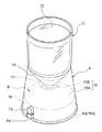
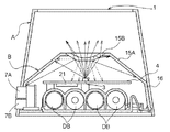
図1〜図5に示すように、上端と下端とに開口部1、2が形成された筒状の本体Aの内部に密封構造のケーシングBを備えると共に、このケーシングBの内部に光源3と、制御基板4と、電池収納部5と、電源スイッチ7及び調光スイッチ8をユニット化したスイッチユニットSWとを備えて照明装置が構成されている。前記スイッチユニットSWの一対の操作ノブ7A、8Aは本体Aの下部の外面に露出する状態で配置してある。そして、この照明装置は、本体Aの上端の開口部1に対して半透明(透明であっても良い)なカップ状の被照明体Cを嵌め込む形態で使用されるものであり、この被照明体Cを光源3からの光線で照明することによって、被照明体Cばかりで無く被照明体Cの内部の収容物の照明も行うよう構成されている。
Hereinafter, embodiments of the present invention will be described with reference to the drawings.
As shown in FIGS. 1 to 5, a casing B having a sealed structure is provided inside a cylindrical main body
この被照明体Cは、その底壁の外周部に前記本体Aの上端の開口部1に接当する接当部10をリング状に形成し、その下部に下方に突出する突出部11を形成した略一定の厚みで上方に開放するカップ状に成形されている。図1には収容物の一例として光線の透過を許す透明のゲル状の芳香剤12を貯留した状態を示している。尚、収納物として芳香剤以外に、鑑賞用の植物や照明によって映える装飾品や装身具が考えられる。
The illuminated body C has a ring-
前記本体Aは平面視で円形で上端側を下端側より少し小径とすることで側面視で台形となる形状で、上端と下端とに円形となる前記開口部1、2が形成されている。この本体Aは光線が透過する透明な樹脂(素材は後述する)で一体的に形成され、この樹脂の表面を磨りガラス状に加工して光線を拡散させるよう構成されている。
The main body A has a circular shape in a plan view and a trapezoidal shape in a side view by making the upper end side slightly smaller in diameter than the lower end side, and the
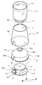
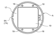
前記ケーシングBは、平面視で円形となる上壁15と、側壁16とを一体成形すると共に、プレート状の底壁17を複数のビス18により固定した構造であり、上壁15と側壁16とに光線が透過する半透明(透明でも良い)な樹脂(素材は後述する)を用いている。又、本体下部の内面に対して環状に凹状の嵌合溝Adを形成してあり、ケーシングBの側壁16の外面には嵌合溝Adに嵌合、及び、分離自在な嵌合部16dを環状に成形してあり、この嵌合部16dを嵌合溝Adに弾性的に嵌合させることで本体AとケーシングBとを連結し、ケーシングBを本体Aから下方に抜き出して、夫々を分離することも可能に構成されている。前記制御基板4は平面視で円形に成形され、この制御基板4の上面側の中央位置に前記光源3を配置してある。特に、ケーシングBの内部に配置される制御基板4の上面には光源3からの光線を吸収しないようにシルク印刷によって白色の塗料の膜を形成してあり、前記操作ノブ7A、8Aを本体Aから露出させるよう、本体Aの下部には切り欠き部が形成されている。
The casing B has a structure in which a
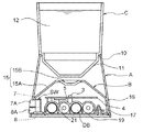
このケーシングBの上壁15は、平面視で円形で上端部が中央側ほど上方に突出する形状に成形した調光部材15Aと、この調光部材15Aの中央位置に嵌め込み固定した凹レンズ15Bとで構成されている。
The
この凹レンズ15Bは調光部材15Aと比較して光線の透過率と屈折率とを高く設定したものであるが、前記本体Aと、ケースBとに同じ素材を用いることも可能である。具体的にはゼオノア(〈シクロオレフィンポリマー〉日本ゼオン株式会社の登録商標)、ポリカーボネート、アクリル等の樹脂が透明性、耐衝撃性から適当であるが、ガラスを用いることも可能である。そして、凹レンズ15Bとして、前述した樹脂を光学レンズと同様に透明な状態で使用することが可能である。又、本体A及びケーシングB(上壁と側壁)として、前述した樹脂を磨りガラスのように表面を加工して光線を拡散させ得る形態で使用することや、着色した樹脂を用いて光源3からの光線を着色する形態で使用することや、半透明な樹脂を用いて間接照明的な光線を得る形態で使用することや、あるいは、表面にアルミニウムや金等の金属薄膜を真空蒸着の技術で形成することにより、表面で光線の一部を反射させる形態で使用することも可能である。
The
このように照明系が構成されているので、電池収納部5に収納された乾電池DBからの電力で光源3を発光させた場合には、光源3から送出された光線が図5に示す如く、凹レンズ15Bに達したものは屈折することで発散し、偏った照明を行うことなく被照明体Cを平均的に照明するものとなる。又、調光部材15Aに達した光線は該調光部材15Aを透過する際に一部が吸収されるものの、この調光部材15Aの内部で散乱し、あたかも、この調光部材15Aの全体が発光するように広い表面から光線を送り出すので、間接照明と同様の柔らかい光線を送出して影を作り難い照明を行うものとなる。又、凹レンズ15Bや調光部材15Aの下面で反射した光線はケーシングBの内部で反射して一層拡散して光量を平均化させるものとなる。特に、調光部材15Aを、中央位置を上方に突出させた形状に成形してあるので、光源3を基準にして調光部材15Aの中央が光源3に接近し過ぎる現象を回避して、光源3からの光線を調光部材15Aへ平均的に送り、偏りの無い照明を行えるものにしている。尚、光源3からの光線が調光部材15Aや、凹レンズ15B、あるいは、被照明体Cを透過する際の光線の方向(屈折による方向)はスネルの法則に従って説明できるものである。
Since the illumination system is configured in this way, when the
従って、本発明では本体Aの上端の開口部1に対してカップ状の芳香剤12等の被照明体Cを載置することにより、この被照明体Cや、被照明体Cの内部に収めた収納物を、光量に偏りのない平均的な光量で照明できるばかりでなく、調光部材15Aで拡散した柔らかい光線で、間接照明のように被照明体Cを照明できるので影を作らない状態での照明を可能にするものとなっている。又、照明時にはケーシングBの内部で乱反射した光線が調光部材15Aから本体に達するので、調光部材15Aや本体Aを照明して、この照明装置全体を明るくして存在感を示すものとなっている。又、このように照明が行われる際には、被照明体Cの下面の突出部11が凹レンズ15Bに近接しているので、被照明体Cの内部に多くの光量を取込んで、芳香剤12等の被照明体Cを強く照明できるものとなっている。
Therefore, in the present invention, the object to be illuminated C such as the cup-shaped
前記光源3は加色法での三原色となる赤色(R)、緑色(G)、青色(B)の3種の高輝度の発光ダイオードLED−R、LED−G、LED−B(発光体の一例、これらの上位概念を発光ダイオードLEDと称する)を1つのパッケージに収納して成り、前記電池収納部5は、複数の乾電池DBが収納される空間を底壁17の成形により形成してあり、この空間を開閉する蓋体19を底壁17に対して着脱自在に備えて構成されている。
The
前記制御基板4の底面側には、本発明の照明制御装置を構成する制御手段としてプログラムがセットされたマイコンで成るコントローラ21を備えている。本発明の照明制御装置では、前記コントローラ21による光源3の制御形態に特徴を有するものであり、その詳細を以下に説明する。
On the bottom side of the
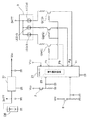
図6に示すように、前記コントローラ21の入力端子に対して前記電源スイッチ7と調光スイッチ8とからの信号を入力する端子が形成されると共に、このコントローラ21には、前記光源3を構成する三原色の発光ダイオードLED−R、LED−G、LED−Bを駆動するバイポーラ型のトランジスタQr、Qg、Qb(電力制御素子の一例)のベース端子に対して制御信号を出力する制御端子Pc(ポート)が形成され、トランジスタQr、Qg、Qbのエミッタ端子の電位を制御する出力端子Pr、Pg、Pb(ポート)が形成されている。尚、3つのトランジスタQr、Qg、Qbの上位概念をトランジスタQ(電力制御素子の一例)と称する。
As shown in FIG. 6, a terminal for inputting signals from the
又、この制御系では、前記電池収納部5に収納された乾電池DBから定電圧回路22を介して送り出される電力をコントローラ21と、電源スイッチ7と、調光スイッチ8とに供給する電力系(VDD)を備えると共に、前記光源3を構成する3種の高輝度の発光ダイオードLED−R、LED−G、LED−Bに対して前記乾電池DBからの電力を供給する電力系(BATT)を備えている。
Further, in this control system, a power system (supplied to the
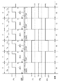
コントローラ21は、予めセットされたプログラムに従って指定した複数の出力端子Pr、Pg、Pbを制御するよう機能すると共に、前記制御端子Pcに対してPWM(Pulse Width Modulation)式に電力を制御する電力設定回路23を内蔵している。前記電力設定回路23は、図7に示す時間間隔T(周期・インターバル)において、時間間隔Tの初期にOFF状態(LOW状態)を維持し、その後、ON状態(HIGH状態)となる信号を出力する形態で設定されたデューティ比(OFF時間txとON時間tyとの比率)の信号を出力するよう出力タイミングが設定されると共に、デューティ比を設定するデータを予めセットすることにより、コントローラ21の外部から供給されるクロック信号を回路内部でハードウエア的に分周する等の処理の後に計数することにより設定されたデューティ比の信号をソフトウエアの影響を受けずに制御端子Pc出力するように構成されたものである。
The
また、このコントローラ21は、前記調光スイッチ8を操作することにより、前記光源3を任意の色相で継続的に発光させるルーチンと、前記光源3から発する光線の色相を時間経過に伴って変化させる複数種のルーチンとがプログラムの形でセットされたものであり、何れのルーチンにおいても光源3からの光線の色相を調整する処理は、電力設定回路23によるPWM(Pulse Width Modulation)式に電力を制御することにより実現している。
In addition, the
このコントローラ21で光源3を制御する際における制御端子Pcの信号を図7のタイミングチャートのように示すことができる。つまり、発光ダイオードLED−R、LED−G、LED−Bに対して、この順序で電力を供給するよう制御の順序が設定されると共に、時間周期Tにおいて設定されたデューティ比で制御端子Pcから信号を出力し、電力を供給すべき発光ダイオードLED−R、LED−G、LED−Bに対応する出力端子Pr、Pg、Pbの何れか1つを指定する処理が実行される。また、このコントローラ21では、時間周期Tの初期のタイミングでデューティ比を設定するデータをセットし、かつ、この初期のタイミングで、その時間周期Tにおいて制御すべき発光ダイオードLEDに対応する出力端子Pr、Pg、Pbの何れかを指定するデータをセットするようデータの設定形態が設定され、その時間周期Tにおいては1周期前にセットされたデューティ比で、その時間周期Tで指定されたデューティ比の信号を指定した発光ダイオードLEDに供給して光源3を発光させるものとなっている。
The signal at the control terminal Pc when the
このように処理が実行されることにより、例えば、緑の発光ダイオードLED−Gを制御する際には、赤の発光ダイオードLED−Rを制御する時間周期Tにおいて緑の発光ダイオードLED−Gを制御するデューティ比のデータを予めセットし、次の時間周期Tにおいて電力を供給すべき発光ダイオードLED−Gに対応する出力端子PgがOFF状態(LOW状態)となり、制御端子Pcからの信号は3つのランジスタQr、Qg、Qbのベース端子に伝えられることにより、3つのランジスタQr、Qg、QbがON状態に達したタイミングで、エミッタ端子が低電位(OFF状態)にあるトランジスタQgに対して発光ダイオードLED−Gからの電流が流れるものとなり、その発光ダイオードLED−Gをデューティ比に対応した光量で発光させることが可能となるのである。 By executing the processing in this manner, for example, when controlling the green light emitting diode LED-G, the green light emitting diode LED-G is controlled in the time period T for controlling the red light emitting diode LED-R. The data of the duty ratio to be set in advance, the output terminal Pg corresponding to the light emitting diode LED-G to be supplied with power in the next time period T is turned off (LOW state), and the signal from the control terminal Pc is three By being transmitted to the base terminals of the transistors Qr, Qg, Qb, at the timing when the three transistors Qr, Qg, Qb reach the ON state, the light emitting diode is applied to the transistor Qg whose emitter terminal is at a low potential (OFF state). The current from the LED-G flows, and the light emitting diode LED-G corresponds to the duty ratio. It from becoming possible to emit light in an amount.
このような制御を実行することによって時間間隔Tにおいて、出力端子Pr、Pg、Pbの何れかの出力端子で指定されるトランジスタをON制御することとなり、そのトランジスタに対応した発光ダイオードLEDを間歇的に駆動し、所謂、PWM制御によって3つの発光ダイオードLED−R、LED−G、LED−Bの光量を順次設定し、加色法により光源3の色相を設定できるのである。
By executing such control, the transistor designated by any one of the output terminals Pr, Pg, and Pb is turned on in the time interval T, and the light emitting diode LED corresponding to the transistor is intermittently controlled. The light quantity of the three light emitting diodes LED-R, LED-G, and LED-B can be set sequentially by so-called PWM control, and the hue of the
このように、本発明によると、調光スイッチ8を操作することにより、予め設定されたプログラムにおいて設定された色相で、設定された光量となるよう光源3が制御され、また、予め設定されたプログラムに基づき時間経過とともに光源3の色相を変化させる形態で光源3を制御できるものとなっている。そして、このように光源3を制御する場合には、光源3を構成する3つの発光ダイオードLED−R、LED−G、LED−Bに供給する電力を電力設定回路23がPWM式に制御するものとなり、この電力設定回路23がハードウエアで構成されているので、光源3に対して電力を供給する際に、コントローラ21の内部において実行されるプログラムに対して割込み処理が発生した場合でも、ソフトウエアの影響を受けることがなく、光源3を所望の色相で発光させ、その色相を滑らかに変更することが可能となったのである。
Thus, according to the present invention, by operating the
特に、電力設定回路23では、設定された時間間隔Tの時間領域の開始時にOFF状態を維持し、その後、ON状態の信号を出力する形態で前記デューティ比の信号を出力するよう処理形態が設定されると共に、OFF状態の時間tx(LOW時間)とON状態の時間ty(HIGH時間)とで表されるデューティ比となるデータを予めセットされるので、制御の直前にデータをセットするものと比較して、ON状態の時間tyに達するまでのタイミングに遅れを招くことがないのである。つまり、この照明装置では、コントローラ21に対して予め設定されたプログラムに基づいて光源3からの光線の色相の設定や、光量の設定が行われるものであるが、現実に光量を制御する際には、光量を調節するタイミング以前に、プログラムのデータを電力設定回路23にセットし、電力を供給する対象を指定するためのデータ(出力端子Pr、Pg、Pbを指定するデータ)をセットし、しかも、現実に光量を制御する際にもトランジスタQを先にOFF状態に設定し、この後、ON状態にすることで電力の供給を開始するので、制御の遅れを発生させないものにして精密な制御を実現しているのである。
〔別実施の形態〕
本発明は、上記した実施の形態以外に以下のように構成しても良い(この別実施の形態では前記実施の形態と同じ機能を有するものには、実施の形態と共通の番号、符号を付している)。
In particular, in the
[Another embodiment]
In addition to the above-described embodiment, the present invention may be configured as follows (in this another embodiment, the same number and code as those of the embodiment are given to those having the same functions as those of the above embodiment). Attached).
(イ)図8に示すように、3つの主ランジスタQr1、Qg1、Qb1のエミッタ端子からの電力をグランド(アース)に流すための副トランジスタQr2、Qg2、Qb2を備え、この副トランジスタQr2、Qg2、Qb2のベース端子を対応する出力端子Pr、Pg、Pbに接続する。これら主トランジスタと副トランジスタとは電力制御素子として機能するものであり、このように構成した場合、発光ダイオードLED−R、LED−G、LED−Bを発光させる際には、出力端子Pr、Pg、Pbの電位を前記実施の形態とは逆に設定する必要がある。このように構成することにより、発光ダイオードLED−R、LED−G、LED−Bを流れた電流をコントローラ21に流す必要がなく、発光ダイオードに大電流を流して高輝度の発光を実現することも可能となる。
(A) As shown in FIG. 8, there are provided sub-transistors Qr2, Qg2, Qb2 for supplying power from the emitter terminals of the three main transistors Qr1, Qg1, Qb1 to the ground (earth), and the sub-transistors Qr2, Qg2 , Qb2 are connected to the corresponding output terminals Pr, Pg, Pb. These main transistors and sub-transistors function as power control elements. When configured in this way, when the light-emitting diodes LED-R, LED-G, and LED-B emit light, the output terminals Pr, Pg , Pb needs to be set in the opposite manner to the above embodiment. By configuring in this way, it is not necessary to flow the current that has flowed through the light emitting diodes LED-R, LED-G, and LED-B to the
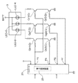
(ロ)図9に示すように、発光ダイオードLED−R、LED−G、LED−B夫々に対応して2つずつの主トランジスタQr1a、Qr1b、Qg1a、Qg1b、Qb1a、Qb1bを並列的に配置し、これらの主トランジスタに電力を供給する系に抵抗値が異なる抵抗器Ra、Rb(これらの上位概念を抵抗器Rと称する)を介装し、また、主トランジスタQr1a、Qr1b、Qg1a、Qg1b、Qb1a、Qb1bのエミッタ端子からの電力をグランド(アース)に流すための副トランジスタQr2a、Qr2b、Qg2a、Qg2b、Qb2a、Qb2bを備え、これらの副トランジスタのベース端子を対応する出力端子Pra、Prb、Pga、Pgb、Pba、Pbbに接続する。このように構成することにより、発光ダイオードLED−R、LED−G、LED−Bを流れた電流をコントローラに流す必要がなく、発光ダイオードに大電流を流して高輝度の発光を実現することも可能となると共に、2つの抵抗器のうちの一方又は双方に電流を流すよう副トランジスタQr2a、Qr2b、Qg2a、Qg2b、Qb2a、Qb2bを制御することにより一層微妙な光量の調節を実現するのである。 (B) As shown in FIG. 9, two main transistors Qr1a, Qr1b, Qg1a, Qg1b, Qb1a, and Qb1b are arranged in parallel corresponding to each of the light emitting diodes LED-R, LED-G, and LED-B. In addition, resistors Ra and Rb having different resistance values are interposed in a system for supplying power to these main transistors (the superordinate concepts are referred to as resistors R), and the main transistors Qr1a, Qr1b, Qg1a, and Qg1b , Qb1a, Qb1b are provided with sub-transistors Qr2a, Qr2b, Qg2a, Qg2b, Qb2a, Qb2b for supplying power from the emitter terminals to the ground (earth), and the base terminals of these sub-transistors are the corresponding output terminals Pra, Prb , Pga, Pgb, Pba, Pbb. By configuring in this way, it is not necessary to flow the current that flows through the light emitting diodes LED-R, LED-G, and LED-B to the controller, and it is possible to realize high luminance light emission by flowing a large current through the light emitting diode. In addition, the sub-transistors Qr2a, Qr2b, Qg2a, Qg2b, Qb2a, and Qb2b are controlled so as to allow current to flow through one or both of the two resistors.
この別実施の形態(ロ)では、副トランジスタQr2a、Qr2b、Qg2a、Qg2b、Qb2a、Qb2bを備えていたが、この副トランジスタを備えず、主トランジスタQr1a、Qr1b、Qg1a、Qg1b、Qb1a、Qb1bのエミッタ端子をコントローラ21の出力端子Pra、Prb、Pga、Pgb、Pba、Pbbに接続しても良い。
In this alternative embodiment (b), the sub-transistors Qr2a, Qr2b, Qg2a, Qg2b, Qb2a, Qb2b are provided, but this sub-transistor is not provided, and the main transistors Qr1a, Qr1b, Qg1a, Qg1b, Qb1a, Qb1b are not provided. The emitter terminal may be connected to the output terminals Pra, Prb, Pga, Pgb, Pba, Pbb of the
(ハ)前記光源として3つ以上の発光ダイオードを用いて構成することや、光源としてフィラメントを有した発光体を用いて構成することも可能である。尚、フィラメントを有した発光体の場合にはR(赤)、G(緑)、B(青)のフィルタ等、特定の波長の光線を選択的に送出すフィルタを用いることになる。 (C) The light source may be configured using three or more light emitting diodes, or the light source may be configured using a light emitter having a filament. In the case of a light-emitting body having a filament, a filter that selectively transmits light of a specific wavelength, such as an R (red), G (green), or B (blue) filter, is used.
3 光源
21 制御手段
23 電力設定回路
Q 電力制御素子
R 抵抗器
T 時間間隔
Pc 制御端子
Pr、Pg、Pb 出力端子
LED 発光体
3
Claims (4)
前記制御手段が、異なる色相の前記発光体に対応した複数の出力端子と、発光体に供給する電力を設定する制御端子とを備えると共に、設定された時間間隔毎に前記制御端子に対して設定されたデューティ比の信号を出力する電力設定回路を備えたコントローラで構成され、
このコントローラは、前記複数の出力端子を指定するデータと、前記電力設定回路に対して前記デューティ比を指定するデータとを含む命令を前記時間間隔毎に実行することにより、前記出力端子と制御端子とを制御するよう構成され、この命令は、先の命令の実行時又は実行以前に予めセットするよう処理形態を設定してある照明制御装置。 An illumination control device comprising a light source having a plurality of light emitters having different emission colors, and comprising a control means for controlling the hue of light emitted from the light source by adjusting the amount of light emitted from each light emitter,
The control means includes a plurality of output terminals corresponding to the light emitters of different hues and a control terminal for setting power to be supplied to the light emitters, and is set for the control terminals at set time intervals. Composed of a controller with a power setting circuit that outputs a signal with a specified duty ratio,
The controller executes the command including data specifying the plurality of output terminals and data specifying the duty ratio for the power setting circuit at each time interval, whereby the output terminal and the control terminal The lighting control device is configured to set the processing form so that the command is set in advance or before execution of the previous command.
Priority Applications (1)
| Application Number | Priority Date | Filing Date | Title |
|---|---|---|---|
| JP2004034781A JP2005228551A (en) | 2004-02-12 | 2004-02-12 | Lighting control device |
Applications Claiming Priority (1)
| Application Number | Priority Date | Filing Date | Title |
|---|---|---|---|
| JP2004034781A JP2005228551A (en) | 2004-02-12 | 2004-02-12 | Lighting control device |
Publications (1)
| Publication Number | Publication Date |
|---|---|
| JP2005228551A true JP2005228551A (en) | 2005-08-25 |
Family
ID=35003090
Family Applications (1)
| Application Number | Title | Priority Date | Filing Date |
|---|---|---|---|
| JP2004034781A Pending JP2005228551A (en) | 2004-02-12 | 2004-02-12 | Lighting control device |
Country Status (1)
| Country | Link |
|---|---|
| JP (1) | JP2005228551A (en) |
Cited By (1)
| Publication number | Priority date | Publication date | Assignee | Title |
|---|---|---|---|---|
| JP2010021008A (en) * | 2008-07-10 | 2010-01-28 | Koizumi Lighting Technology Corp | Led lighting device |
-
2004
- 2004-02-12 JP JP2004034781A patent/JP2005228551A/en active Pending
Cited By (1)
| Publication number | Priority date | Publication date | Assignee | Title |
|---|---|---|---|---|
| JP2010021008A (en) * | 2008-07-10 | 2010-01-28 | Koizumi Lighting Technology Corp | Led lighting device |
Similar Documents
| Publication | Publication Date | Title |
|---|---|---|
| JP5243964B2 (en) | Lighting device | |
| US6472823B2 (en) | LED tubular lighting device and control device | |
| US7063441B2 (en) | Soft light fixture | |
| CN100576964C (en) | Photogenerator | |
| US7434955B2 (en) | Flashlight system | |
| US6890086B2 (en) | Electronically controlled multi-light flashlight | |
| US20090243495A1 (en) | Adjustable lighting device | |
| CA2603622A1 (en) | Night light with fragrance dispenser | |
| US20110286211A1 (en) | Luminaire | |
| US9713221B2 (en) | Luminaire | |
| JP2020123576A (en) | Bar light | |
| US20020105286A1 (en) | Relatively movable illumination device for diverse visual effect | |
| JP2004342399A (en) | Lighting control device | |
| JP2005228551A (en) | Lighting control device | |
| US20040105279A1 (en) | Light-emitting device with light softening cover | |
| US20040070964A1 (en) | Automobile instrument panel lighting fixture | |
| JP2003187615A (en) | Electronic candle | |
| US7350932B2 (en) | Pressed key structure with lighting module | |
| CN112136171A (en) | Electrical devices for vehicle pedals | |
| JP3771244B2 (en) | Electronic candle | |
| KR100721610B1 (en) | Car interior light lighting device | |
| JP4311283B2 (en) | Lighting device | |
| CN106523941A (en) | a lighting module | |
| JP2002289005A (en) | Lighting equipment | |
| JP2006093012A (en) | Lighting device |
Legal Events
| Date | Code | Title | Description |
|---|---|---|---|
| A621 | Written request for application examination |
Free format text: JAPANESE INTERMEDIATE CODE: A621 Effective date: 20051122 |
|
| A977 | Report on retrieval |
Free format text: JAPANESE INTERMEDIATE CODE: A971007 Effective date: 20081107 |
|
| A131 | Notification of reasons for refusal |
Free format text: JAPANESE INTERMEDIATE CODE: A131 Effective date: 20081127 |
|
| A02 | Decision of refusal |
Free format text: JAPANESE INTERMEDIATE CODE: A02 Effective date: 20090319 |