JP2005218218A - Drive power supply - Google Patents
Drive power supply Download PDFInfo
- Publication number
- JP2005218218A JP2005218218A JP2004021607A JP2004021607A JP2005218218A JP 2005218218 A JP2005218218 A JP 2005218218A JP 2004021607 A JP2004021607 A JP 2004021607A JP 2004021607 A JP2004021607 A JP 2004021607A JP 2005218218 A JP2005218218 A JP 2005218218A
- Authority
- JP
- Japan
- Prior art keywords
- power supply
- power source
- rotating
- drive power
- piezoelectric oscillator
- Prior art date
- Legal status (The legal status is an assumption and is not a legal conclusion. Google has not performed a legal analysis and makes no representation as to the accuracy of the status listed.)
- Pending
Links
Images
Landscapes
- Apparatuses For Generation Of Mechanical Vibrations (AREA)
- Charge And Discharge Circuits For Batteries Or The Like (AREA)
Abstract
【課題】 主に回転した回転装置に搭載する圧電発振器など電気回路を駆動する電源手段の扱いを簡素化することを目的とする。
【解決手段】 課題を解決するために本発明は、回転する実装基盤下で使用する圧電発振器など電気回路に供給する回転基盤上の駆動電源において、該電源を回転運動エネルギーあるいは光エネルギーを利用して該圧電発振器など電気回路の駆動電源に用いることを特徴とする回転基盤上の駆動電源として用いることにより課題を解決する。
【選択図】 図2PROBLEM TO BE SOLVED: To simplify the handling of power supply means for driving an electric circuit such as a piezoelectric oscillator mounted mainly on a rotating rotating device.
In order to solve the problems, the present invention relates to a driving power source on a rotating base that supplies an electric circuit such as a piezoelectric oscillator used under a rotating mounting base, using the rotational kinetic energy or light energy. Thus, the present invention solves the problem by using it as a driving power source on a rotating base, which is used as a driving power source for an electric circuit such as the piezoelectric oscillator.
[Selection] Figure 2
Description
主に回転した回転装置に搭載する圧電発振器を駆動する電源手段に関するものである。 The present invention mainly relates to a power supply means for driving a piezoelectric oscillator mounted on a rotating rotating device.
旧来から改善し進化する自動車の安全対策について、最近は自動車を運転し走行する上で、各部の電子制御による安全策が強化されている。一例を挙げるとカーブ走行時の車両姿態の振れや、アクセルを踏みすぎた場合のタイヤの空転(ホイールスピン現象)を補正するトラクション制御(TRC)があったり、車両制動時にタイヤがロックし不用意に制動距離を長くしないためのアンチロックブレーキシステム(ABS)などがあり、その各所で圧電発振器は制御回路のクロック信号とし利用されている。 With regard to automobile safety measures that have improved and evolved from the past, recently, safety measures by electronic control of each part have been strengthened when driving and driving a car. For example, there is traction control (TRC) that corrects the swing of the vehicle when driving on a curve, tire slipping (wheel spin phenomenon) when the accelerator is stepped too much, and the tire locks when the vehicle is braked. There is an anti-lock brake system (ABS) for preventing the braking distance from becoming long, and the piezoelectric oscillator is used as a clock signal for the control circuit in various places.
圧電発振器を用いたクロック信号の利用については、上述する以外にも、自動車の車両に装備する各種計器類の駆動や表示など車両一台をとっても幅広い部位で活用されている現状にある。 Regarding the use of a clock signal using a piezoelectric oscillator, in addition to the above, the present situation is that it is used in a wide range of parts such as driving and displaying various instruments equipped in a vehicle of a car.
そして、最近では自動車車両の安全対策としてタイヤの空気圧をリアルタイムで監視しタイヤのパンクや空気圧不足を運転手に伝えるなどの安全対策も展開されている。その具体的な監視システムとしては、既にタイヤ空気圧モニタリングシステム(TPMS)が製品化されており、監視システムの動作例としては一定周期でタイヤの空気圧異常を検知するものである。 Recently, safety measures such as monitoring tire pressures in real time to inform the driver of tire punctures or lack of air pressure have been developed as safety measures for automobile vehicles. As a specific monitoring system, a tire pressure monitoring system (TPMS) has already been commercialized. As an example of the operation of the monitoring system, tire pressure abnormality is detected at a constant cycle.
ところで、水晶振動子や水晶発振器は水晶素板(圧電素子)あるいは周辺発振回路をパッケージに収容した密閉構造となっている。この場合の収納用パッケージは、例えば酸化アルミニウム質焼結体等のセラミックス材料や有機材料から成り、水晶素板を収容するための凹部を有する構造とフタとの組み合わせで密閉構造にしたものが一般的である。 By the way, the crystal resonator and the crystal oscillator have a sealed structure in which a crystal base plate (piezoelectric element) or a peripheral oscillation circuit is accommodated in a package. The storage package in this case is made of a ceramic material such as an aluminum oxide sintered body or an organic material, and is generally a sealed structure by combining a structure having a recess for accommodating a crystal base plate and a lid. Is.
そして圧電発振器の場合には外部から収納パッケージ内部の周辺発振回路を駆動するために電源を供給する必要があり、水晶素板と発振回路の組み合わせで発振回路が成り立ち、前述する各種制御系のクロック信号を発生することができる。
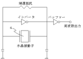
参考として図3にインバータを用いた発振回路例を描画する。
In the case of a piezoelectric oscillator, it is necessary to supply power to drive the peripheral oscillation circuit inside the storage package from the outside, and an oscillation circuit is formed by a combination of a crystal base plate and an oscillation circuit. A signal can be generated.
For reference, an example of an oscillation circuit using an inverter is depicted in FIG.
上述が背景技術であるが特許公報については、出願人は本願特許の出願までに本発明に関連する先行技術文献を発見するに至らなかった。 Although the above is the background art, regarding the patent publication, the applicant has not found prior art documents related to the present invention before the filing of the present patent.
前述のように主にはタイヤの空気圧検出用のセンサにあっては、そのセンサを圧電部品により構成しようとする場合には、当然ながら水晶素板と周辺発振回路部品との組み合わせによる発振器が必要となってくる。そして発振器駆動するには電源は必要不可欠な存在である。実際にタイヤの空気圧検出用に上述の発振器を組み込んだ場合では、電源供給の手段にも工夫が必要であるが、一例として蓄電池を利用した電源も含めて実装するという考えが挙げられるが定期的に電源の交換を必要とすることになる。 As described above, in the case of a tire pressure sensor, if an attempt is made to configure the sensor with a piezoelectric component, naturally an oscillator based on a combination of a crystal base plate and peripheral oscillation circuit components is required. Will come. A power source is indispensable for driving an oscillator. When the above-mentioned oscillator is actually incorporated for tire pressure detection, it is necessary to devise a means for supplying power, but as an example, the idea of mounting including a power source using a storage battery can be given periodically. It will be necessary to replace the power supply.
本発明では、タイヤの空気圧を監視するための圧電発振器の動作や特性を確認する検査装置として発明者が苦労の末に考えたものであり、長時間の使用でも安定して電源を供給できるシステムとして、回転している運動エネルギーや外部からの光エネルギーを利用した電源で発振器など電気回路を駆動するものである。 In the present invention, the inventor considered after a hard time as an inspection device for confirming the operation and characteristics of a piezoelectric oscillator for monitoring the air pressure of a tire, and a system that can stably supply power even after long-term use As described above, an electric circuit such as an oscillator is driven by a power source using rotating kinetic energy or light energy from the outside.
本発明により高速回転する回転物に発振器を実装しその発振器に供給する電源を回転運動エネルギーあるいは、光エネルギーから得ることで安定した電源供給を得ることができる。その結果本来の目的である発振器を使ったセンサの安定度と電源を交換する手間を改善することができる。 According to the present invention, a stable power supply can be obtained by mounting an oscillator on a rotating object that rotates at high speed and obtaining the power to be supplied to the oscillator from rotational kinetic energy or light energy. As a result, it is possible to improve the stability of the sensor using the oscillator, which is the original purpose, and the trouble of replacing the power source.
本発明は回転する実装基盤下で使用する圧電発振器など電気回路に供給する回転基盤上の駆動電源において、該電源を回転運動エネルギーあるいは光エネルギーを利用して該圧電発振器など電気回路の駆動電源に用いることを特徴とする回転基盤上の駆動電源として用いるものである。 The present invention relates to a driving power source on a rotating board for supplying an electric circuit such as a piezoelectric oscillator used under a rotating mounting board, and the power source is used as a driving power source for the electric circuit such as a piezoelectric oscillator using rotational kinetic energy or light energy. It is used as a drive power source on a rotating base characterized by being used.
その具体的な方法としては、回転運動エネルギーについては、回転運動を電気に変換する変換器により電源を得るものであり、光エネルギーについては、外部からの光を電気に変換する変換器により電源を得るものである。 As a specific method, for rotational kinetic energy, a power source is obtained by a converter that converts rotational motion into electricity. For light energy, a power source is obtained by a converter that converts light from the outside into electricity. To get.
要するに、従来から用いる駆動電源とは蓄電池などを発振器と共に実装しその蓄電池を電源として利用していたことを、本発明の電源に置き換えることを特徴とするものである。 In short, the drive power supply used conventionally is characterized in that a storage battery or the like is mounted together with an oscillator and the storage battery is used as a power supply, which is replaced with the power supply of the present invention.
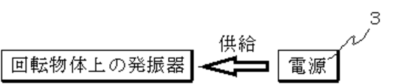
以下本発明による一実施形態を図面を参照しながら説明する。図1は本発明の回転基盤上の駆動電源3の概念を示すものである。回転する円盤上に回転自体の動作を認識するセンサ(本願では一例としてタイヤの空気圧を認識)が実装されている。センサの回路構成としては圧電発振器2と例えば水晶からなる圧電素板4との組み合わせによるものである。
Hereinafter, an embodiment of the present invention will be described with reference to the drawings. FIG. 1 shows the concept of the
ここで発振器2など電気回路を動作するためには従来では蓄電池などの電源を用いていたが本発明では回転する実装基盤1下で使用する圧電発振器2に供給する回転基盤上の駆動電源3を、電源を回転運動エネルギーあるいは光エネルギーを利用して圧電発振器2など電気回路の駆動電源3に用いることを特徴とする。
Here, in order to operate an electric circuit such as the oscillator 2, a power source such as a storage battery has been conventionally used. However, in the present invention, a
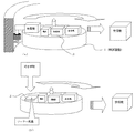
具体的には図2に示すような構成である。図2(a)は回転運動エネルギーから電源を得るものであり、回転する円盤に例えばダイナモ(電磁誘導)を付けて図中左端で回転するこのダイナモにより発電させるものである。また、図2(b)では光エネルギーから電源を得る概念を示すものである。外部からの光を太陽電池で受けてそこで発電させるものである。 Specifically, the configuration is as shown in FIG. In FIG. 2A, power is obtained from rotational kinetic energy. For example, a dynamo (electromagnetic induction) is attached to a rotating disk and power is generated by this dynamo rotating at the left end in the figure. FIG. 2B shows the concept of obtaining power from light energy. It receives light from the outside with a solar cell and generates electricity there.
上記の発電は共に発振器2など電気回路を駆動するための電源として利用するもので、回転運動や光を受ける状態であれば半永久的に発電することができる。そして予備的に蓄電池も併用することで、供給する電源のより安定度を高めることは言うまでも無い。 Both of the above power generations are used as a power source for driving an electric circuit such as the oscillator 2 and can generate power semipermanently as long as they receive rotational motion and light. And it goes without saying that the stability of the power supply to be supplied is increased by using a storage battery in combination.
なお、図3に示す回路図はインバータを用いた発振回路の一例で、圧電素子4の両端に並列に帰還抵抗とインバータを接続し、その両端はコンデンサを介して接地してある。インバータの一端からバッファーを経由して得られた信号が発振周波数となる。前述する電源とは上記インバータを駆動するために直流電源の2ボルト〜5ボルト程度が必要となってくる。また、供給する電源を充電式電池として、その電池に対して充電する電源として回転運動エネルギーあるいは、光エネルギーを利用することもできる。 The circuit diagram shown in FIG. 3 is an example of an oscillation circuit using an inverter. A feedback resistor and an inverter are connected in parallel to both ends of the piezoelectric element 4, and both ends are grounded via a capacitor. A signal obtained from one end of the inverter via the buffer becomes the oscillation frequency. The power source described above requires about 2 to 5 volts of DC power to drive the inverter. Further, the power source to be supplied can be a rechargeable battery, and rotational kinetic energy or light energy can be used as a power source for charging the battery.
本発明ではセンサを構成する圧電発振器など電気回路の駆動するための電源について記述しているが、微小電圧で動作する回路に供給する電源としても利用することができる。 Although the present invention describes a power source for driving an electric circuit such as a piezoelectric oscillator constituting a sensor, it can also be used as a power source for supplying a circuit operating with a minute voltage.
1 実装基盤
2 圧電発振器
3 駆動電源
4 圧電素子
DESCRIPTION OF SYMBOLS 1 Mounting base 2
Claims (3)
該電源を回転運動エネルギーあるいは光エネルギーを利用して該圧電発振器など電気回路の駆動電源に用いることを特徴とする駆動電源。 In the drive power supply on the rotating base that supplies electric circuits such as piezoelectric oscillators used under the rotating mounting base,
A drive power supply characterized in that the power supply is used as a drive power supply for an electric circuit such as the piezoelectric oscillator by using rotational kinetic energy or light energy.
Priority Applications (1)
| Application Number | Priority Date | Filing Date | Title |
|---|---|---|---|
| JP2004021607A JP2005218218A (en) | 2004-01-29 | 2004-01-29 | Drive power supply |
Applications Claiming Priority (1)
| Application Number | Priority Date | Filing Date | Title |
|---|---|---|---|
| JP2004021607A JP2005218218A (en) | 2004-01-29 | 2004-01-29 | Drive power supply |
Publications (1)
| Publication Number | Publication Date |
|---|---|
| JP2005218218A true JP2005218218A (en) | 2005-08-11 |
Family
ID=34905195
Family Applications (1)
| Application Number | Title | Priority Date | Filing Date |
|---|---|---|---|
| JP2004021607A Pending JP2005218218A (en) | 2004-01-29 | 2004-01-29 | Drive power supply |
Country Status (1)
| Country | Link |
|---|---|
| JP (1) | JP2005218218A (en) |
-
2004
- 2004-01-29 JP JP2004021607A patent/JP2005218218A/en active Pending
Similar Documents
| Publication | Publication Date | Title |
|---|---|---|
| CN100374311C (en) | power generator | |
| CN101754873B (en) | Method and system for generating electrical energy within vehicle tyre | |
| US7285868B2 (en) | Apparatus and method for energy generation within a tire | |
| JP2008526596A (en) | Tire module and pneumatic tire having tire module | |
| AU2003296839A1 (en) | Method and system for generating electrical energy within a vehicle tyre | |
| CN105720738A (en) | Inertia generator | |
| JP2006223054A (en) | Tire with power generator | |
| JP2003154826A (en) | Operating voltage generator for vehicle-mounted electronic subassembly | |
| JP2005218218A (en) | Drive power supply | |
| CN101259820A (en) | Passive automobile tyre early warning system | |
| KR102085006B1 (en) | Self generating device | |
| CN100509452C (en) | Tire-mounted electronic device | |
| US9214896B2 (en) | Frequency generator assembly | |
| IT201800020335A1 (en) | PNEUMATIC INCLUDING A DETECTION DEVICE | |
| US11787243B2 (en) | Electronic unit for measuring operating parameters of a vehicle wheel and suitable for being positioned on the inner surface of a tread of a tire | |
| KR101503378B1 (en) | Power feeder to maintain tire air pressure | |
| KR20140008695A (en) | Power device for auxiliary electric power supplier of vehicle | |
| KR20140083740A (en) | Power device for electric power supplier of vehicle | |
| JPS6382607U (en) | ||
| JP2011223688A (en) | Electrically driven vehicle |
Legal Events
| Date | Code | Title | Description |
|---|---|---|---|
| A621 | Written request for application examination |
Free format text: JAPANESE INTERMEDIATE CODE: A621 Effective date: 20070129 |
|
| A131 | Notification of reasons for refusal |
Free format text: JAPANESE INTERMEDIATE CODE: A131 Effective date: 20071121 |
|
| A02 | Decision of refusal |
Free format text: JAPANESE INTERMEDIATE CODE: A02 Effective date: 20080409 |